Week - 5 - Modelling Spotwelds
Aim:
To model spotwelds for the given assembly of parts and run a crash test.
Procedure:
Case 1 (Spotweld-Beam):
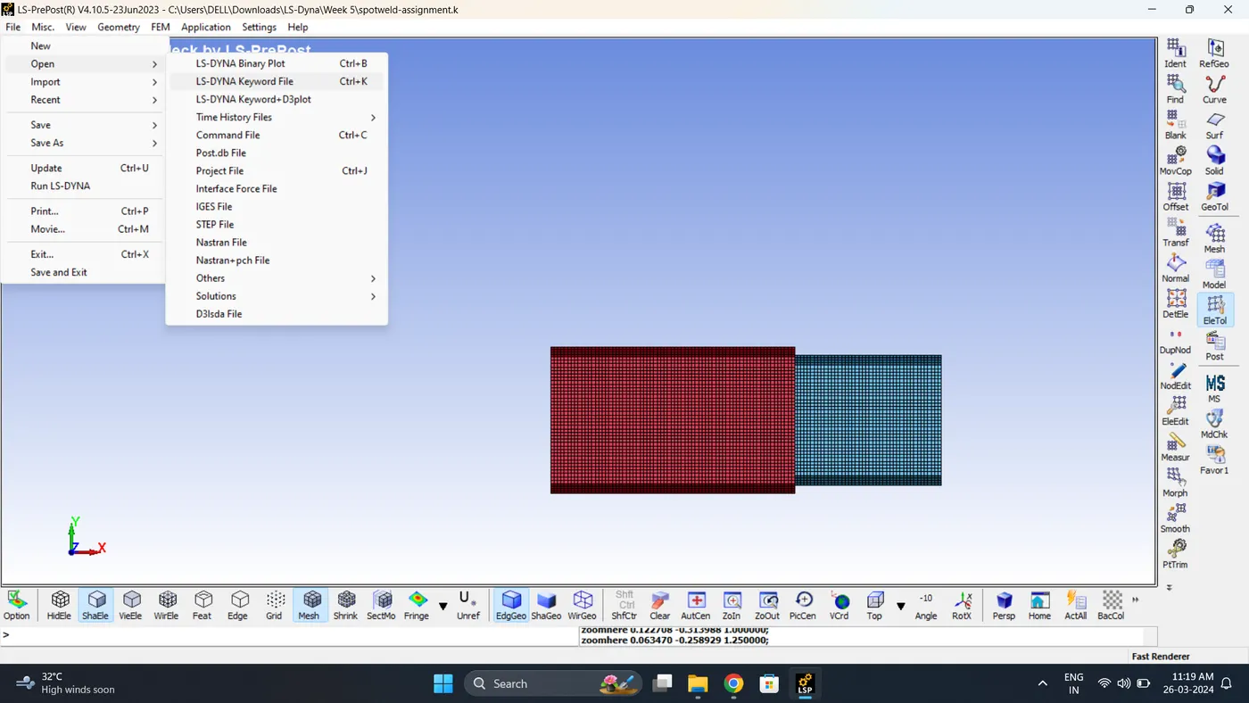
1. Import the model. Go to File - Open - LS-Dyna Keyword file.
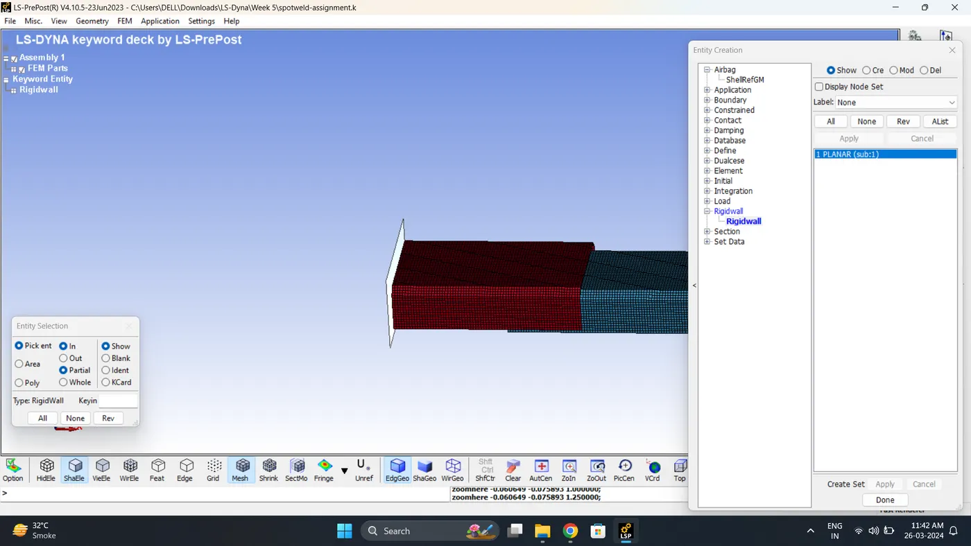
2. 2. Create a Rigid wall. Go to Model - Create Entity - Rigid wall.
Note: Rigid wall normal should be perpendicular to Box
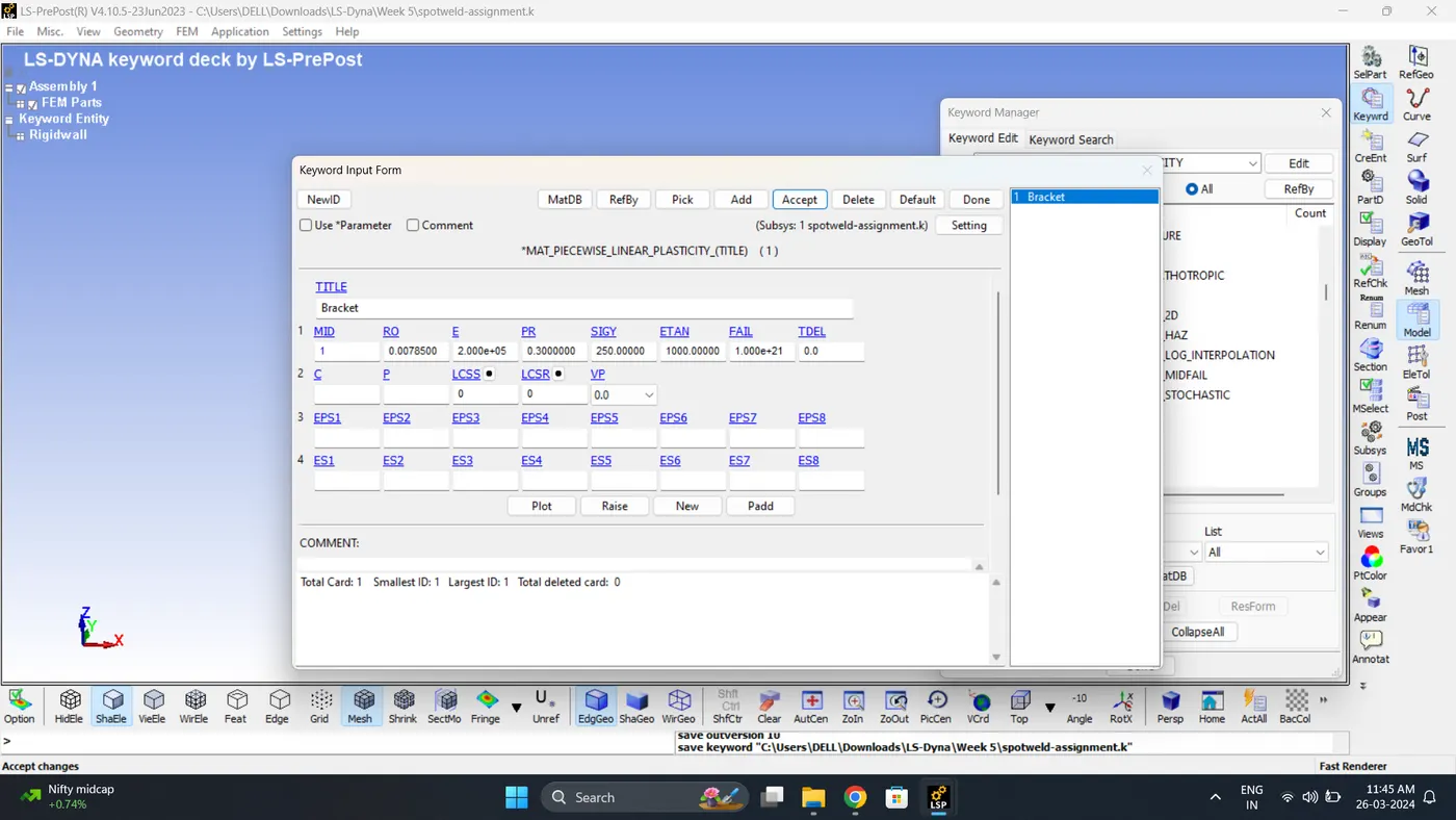
3. Create a Material card. Go to Model - Keyword Manger - MAT - 024_Piecewise_Linear_Plasticity.
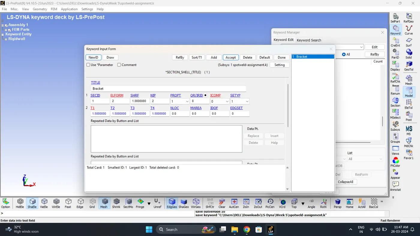
4. Create a section for shell. Go to Model - Keyword Manger - Section - Shell.
5. Create a Hourglass control card. Go to Model - Keyword Manger - Hourglass.
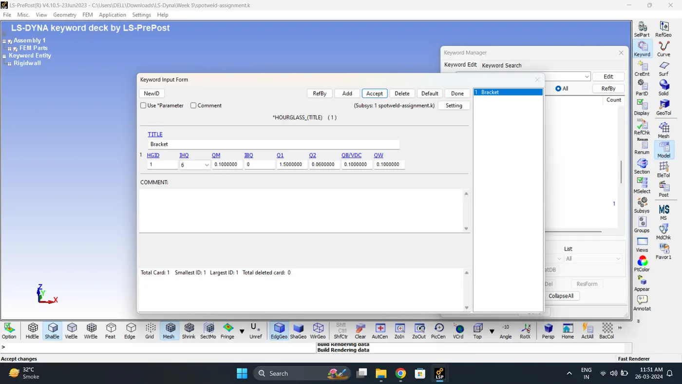
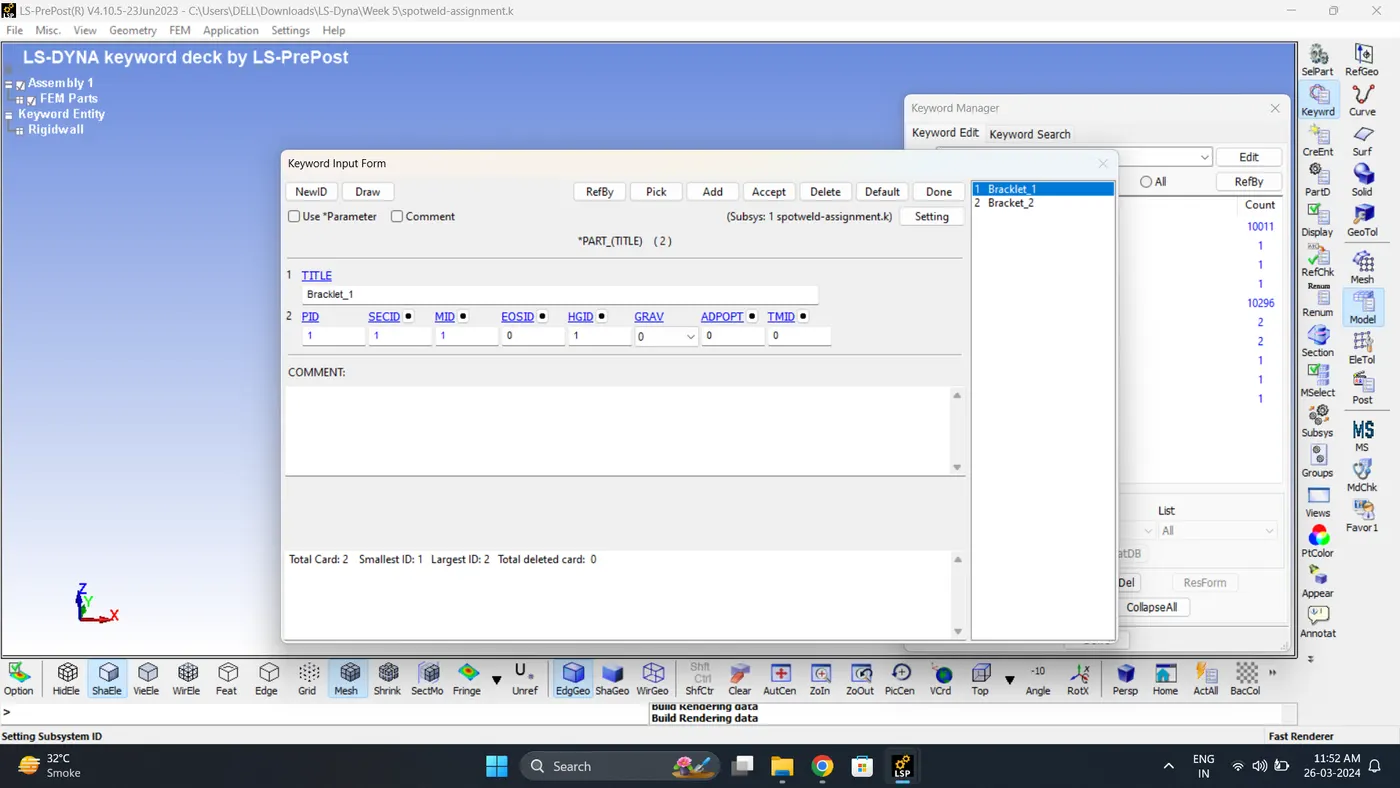
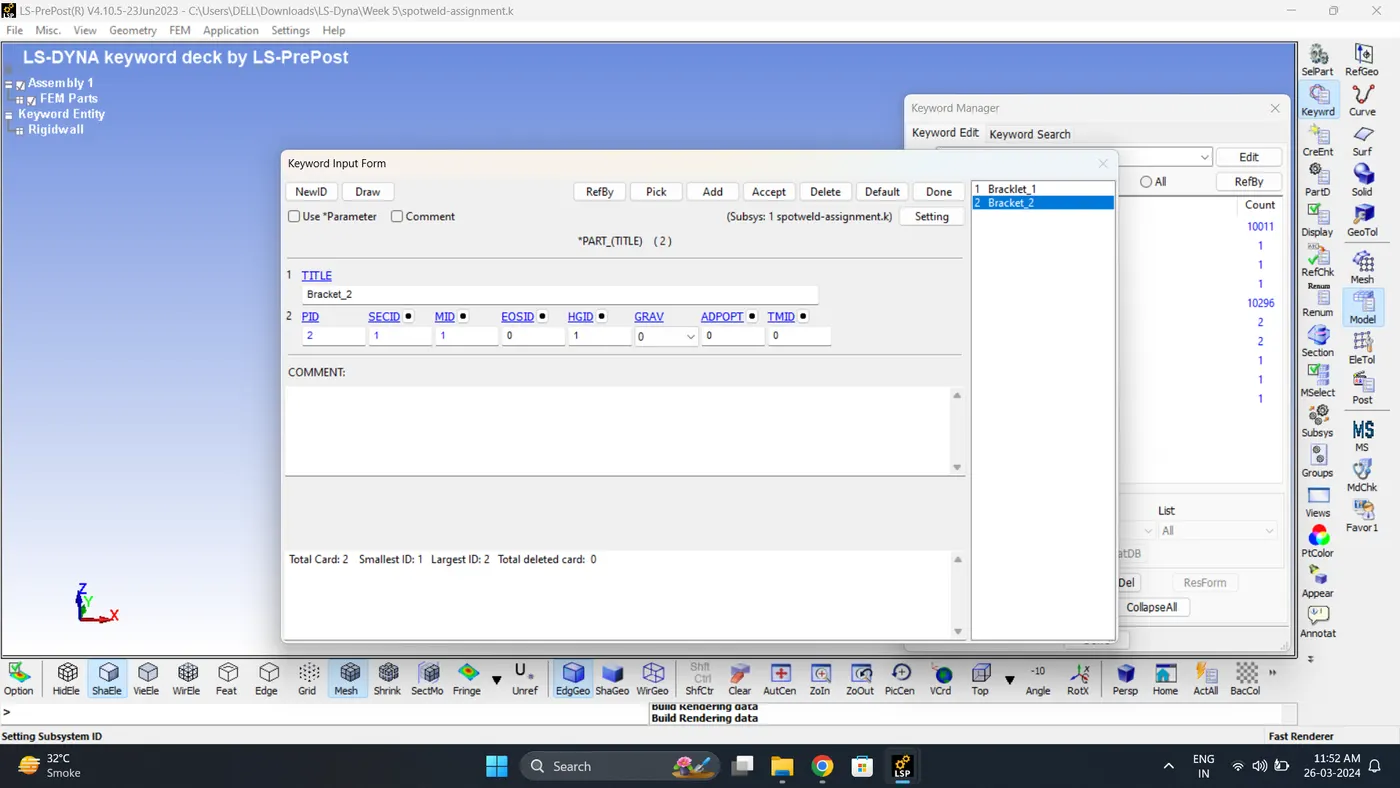
6. Assign section, Material, Hourglass to Part Bracket 1 & 2.
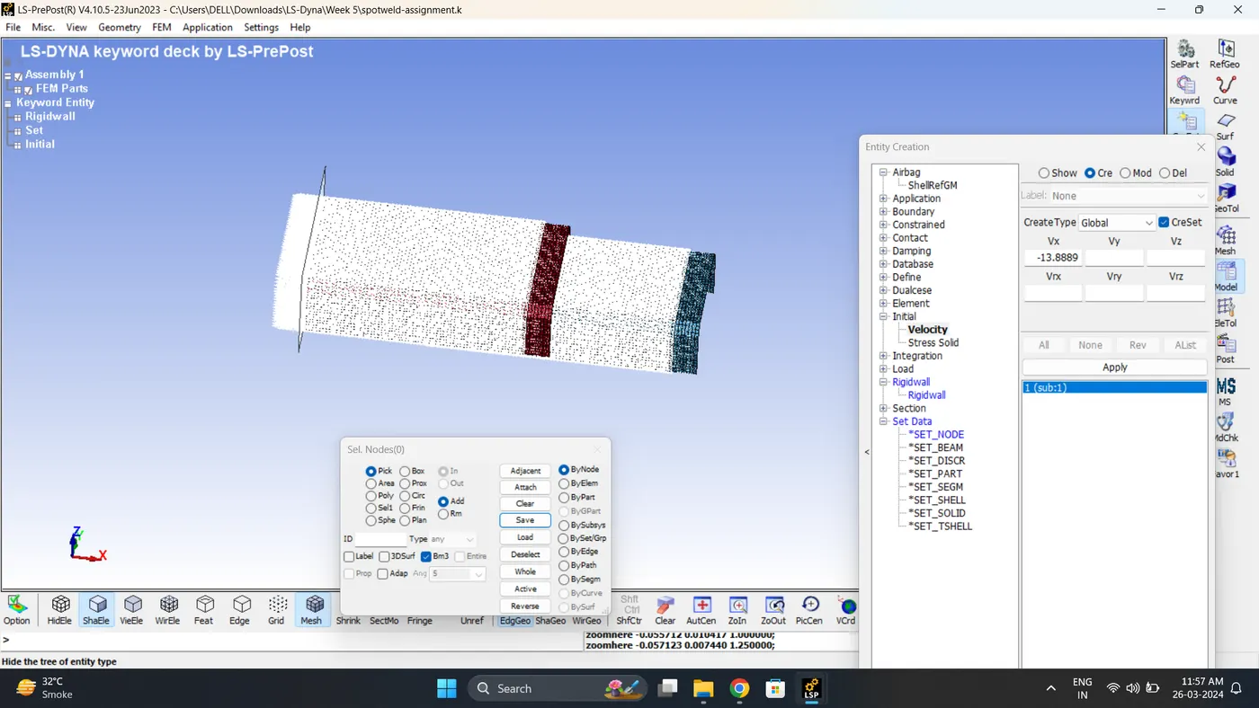
7. Give Initial Velocity. Go to Model - Create Entity - Initial - Velocity.
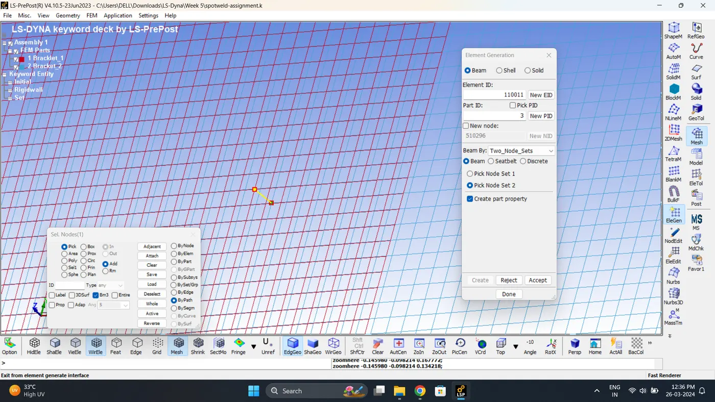
8. Create a Beam element. Go to Mesh - Element Generation.
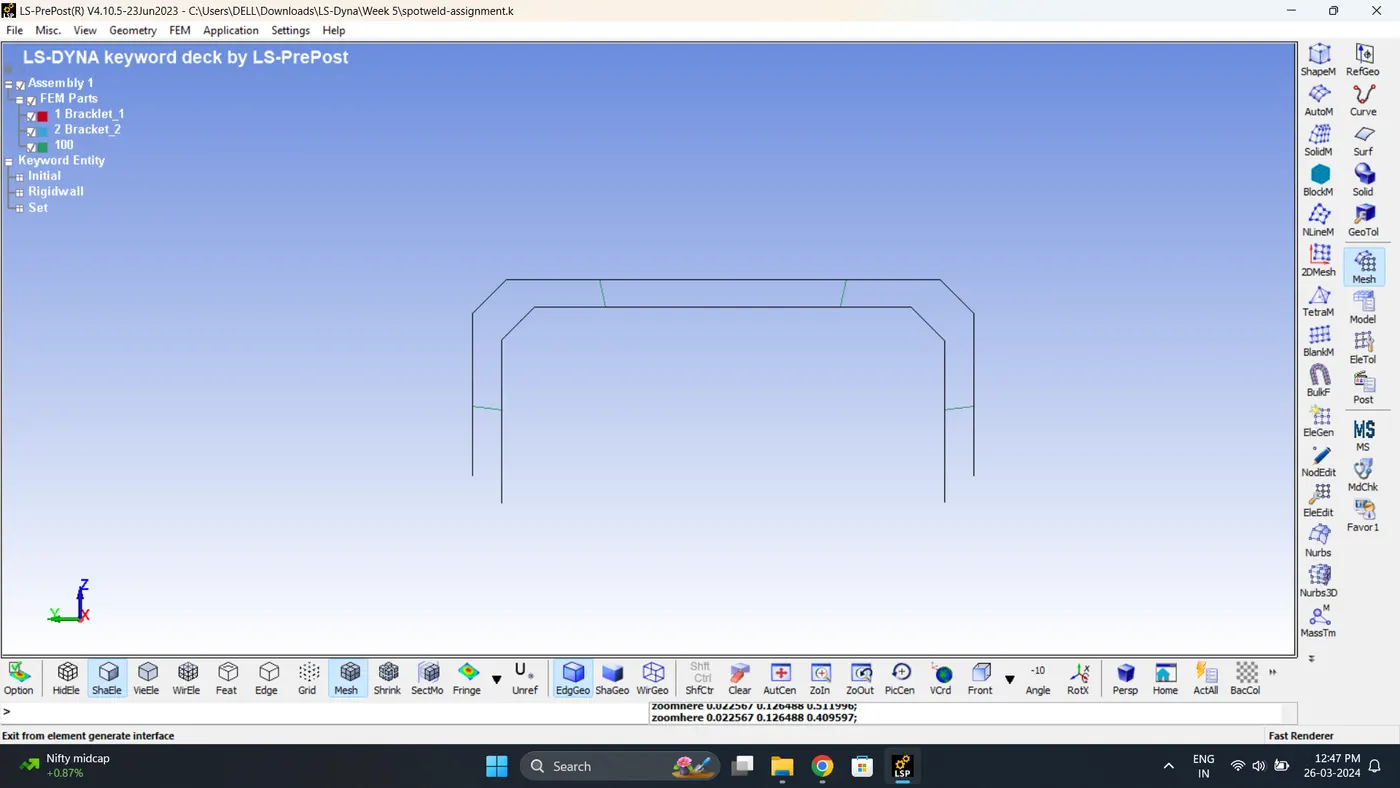
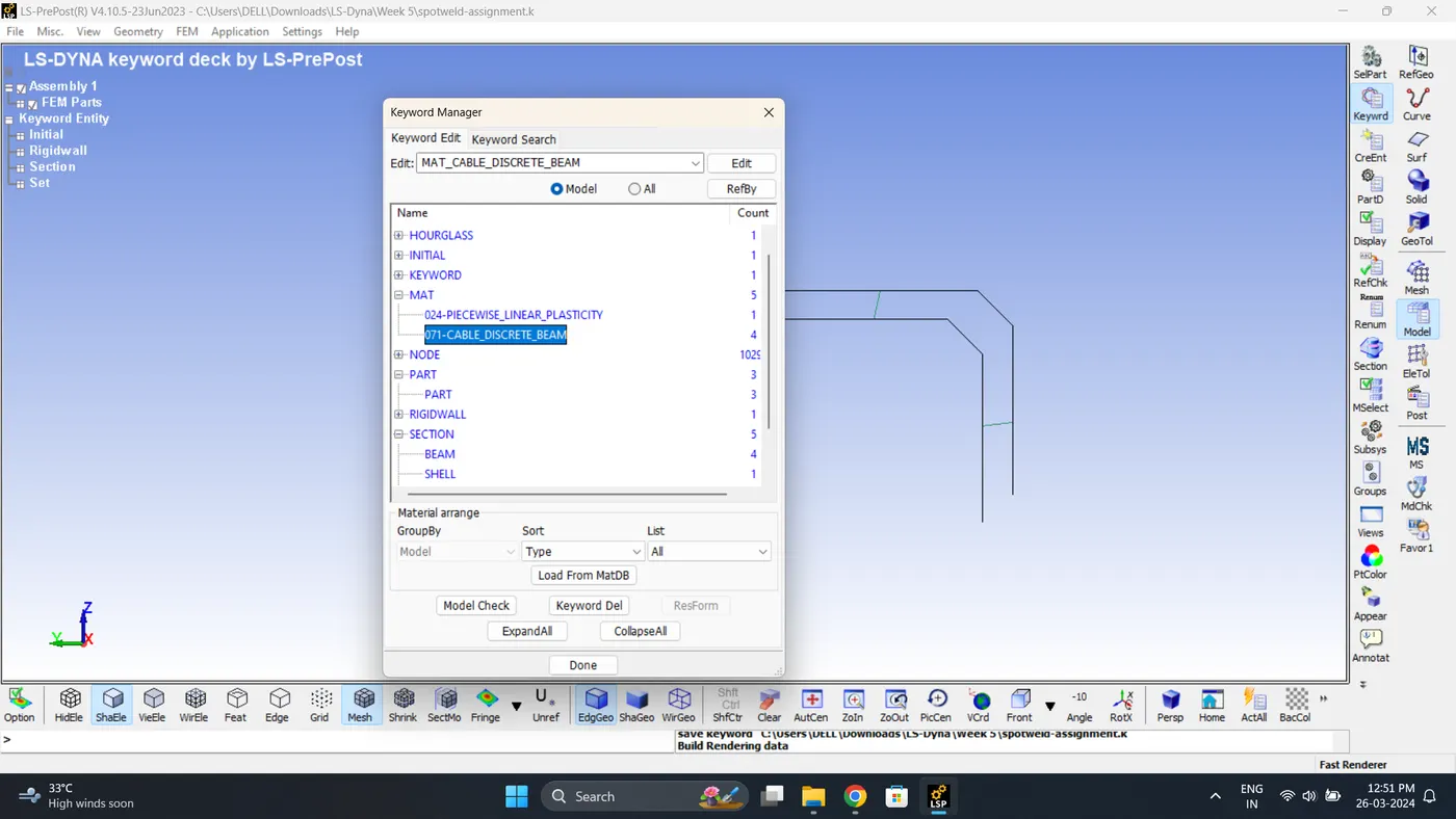
9. Delete the Automatic created Section and Material of a Beam.
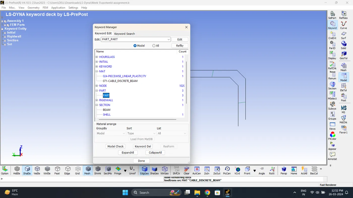
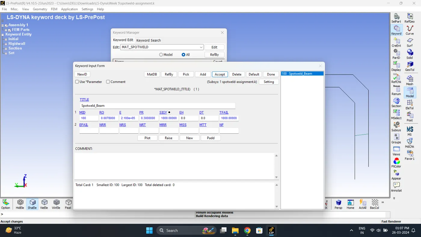
10. Create a material for spot weld. Go to Model - Keyword - MAT - 100-SPOTWELD.
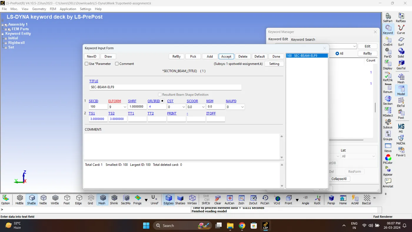
11. Create a section for Weld. Go to Model - Keyword Manger - Section - Beam.
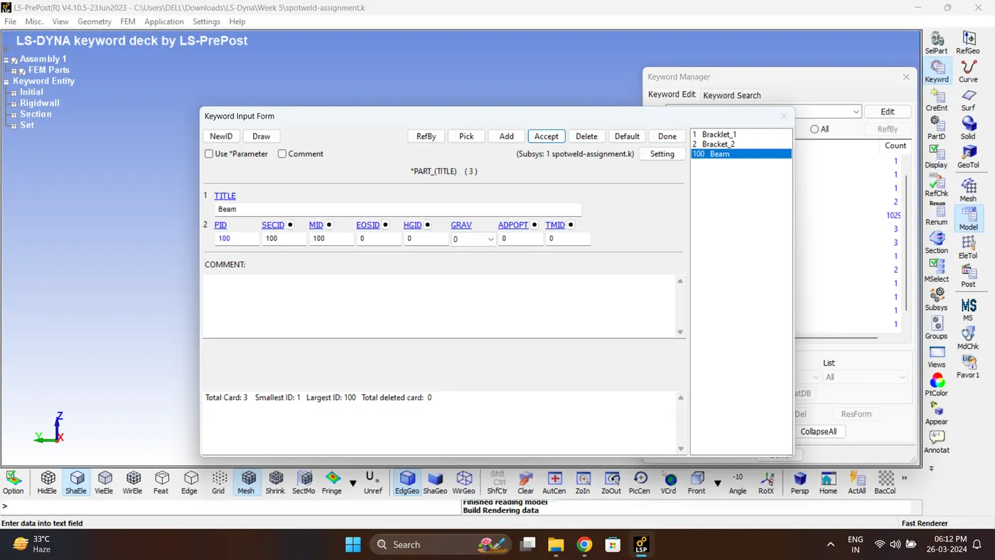
12. Assign section, Material to Part Beam.
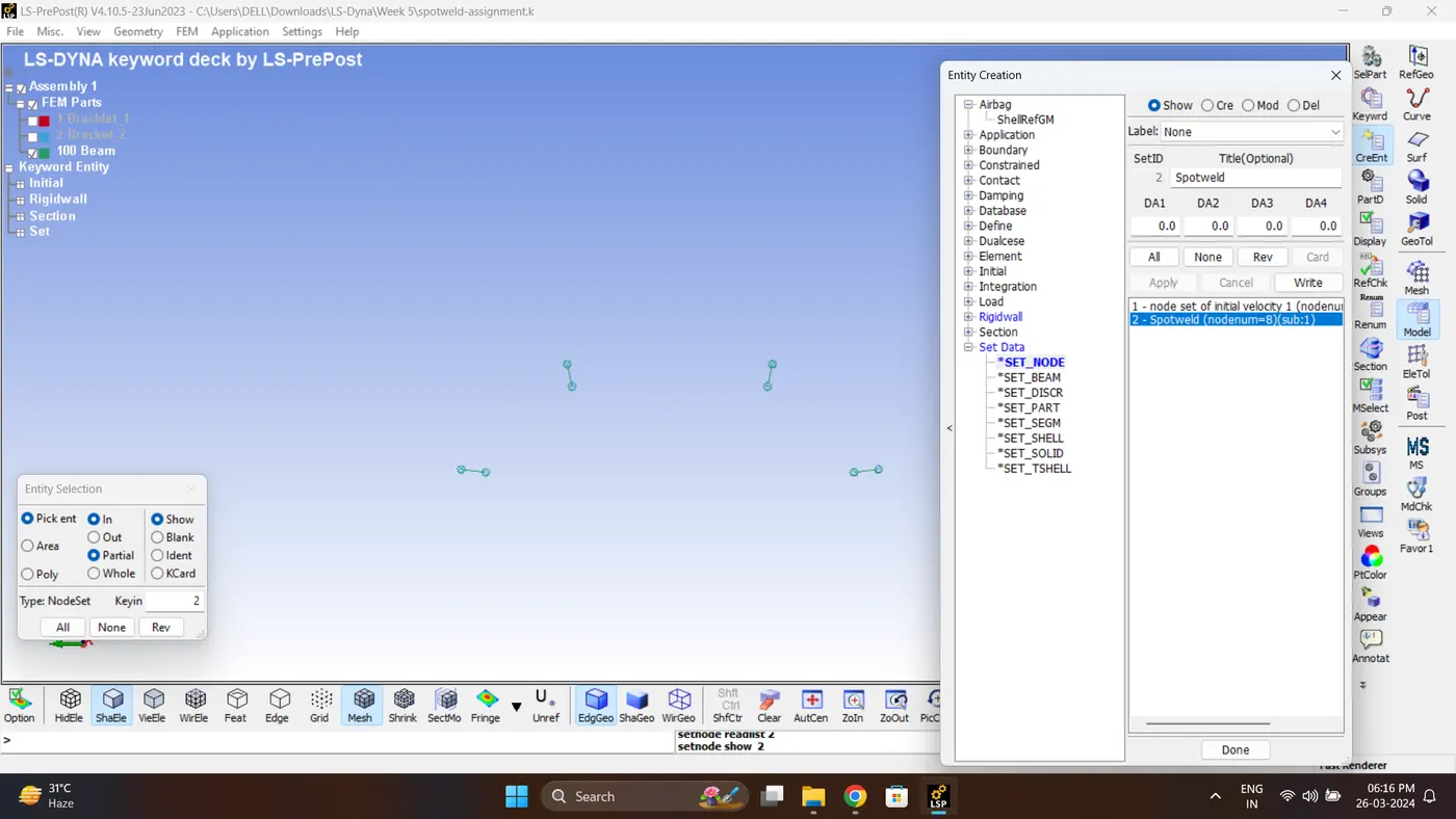
13. Create a Node set of spotweld. Go to Model - Create Entity - Set Data - Set Node.
14. Create a set part consist of two brackets. Go to Model - Create Entity - Set Data - Set Part.
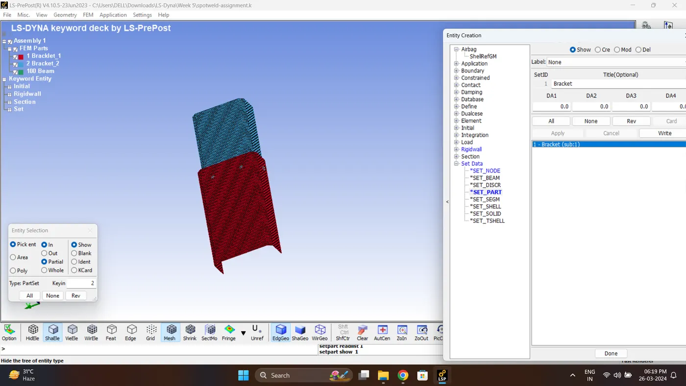
15. Create a Tied Shell Edge to Edge Contact. Go to Model - Keyword manager - Contact - Tied_Shell_Edge_to_Edge.
Select spotweld node sets as slave and bracket part set as master.
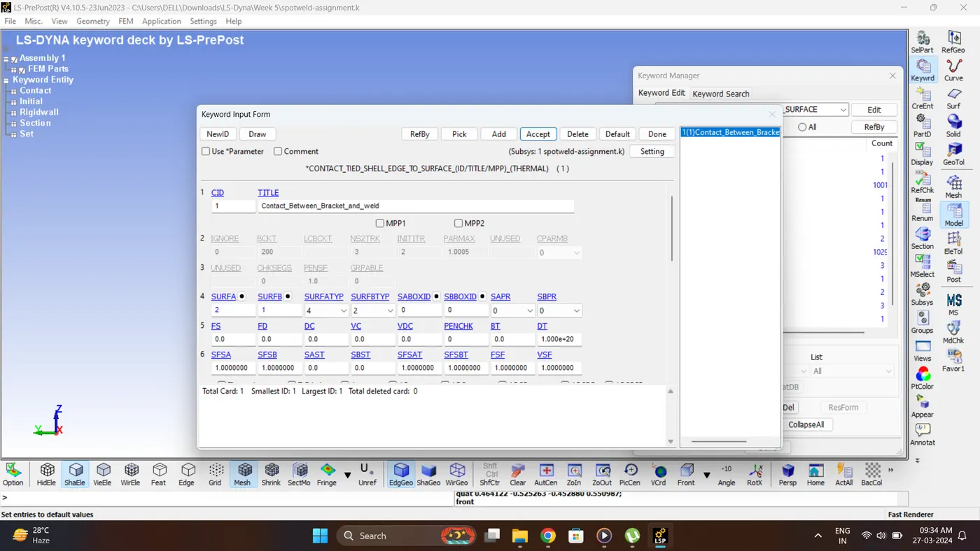
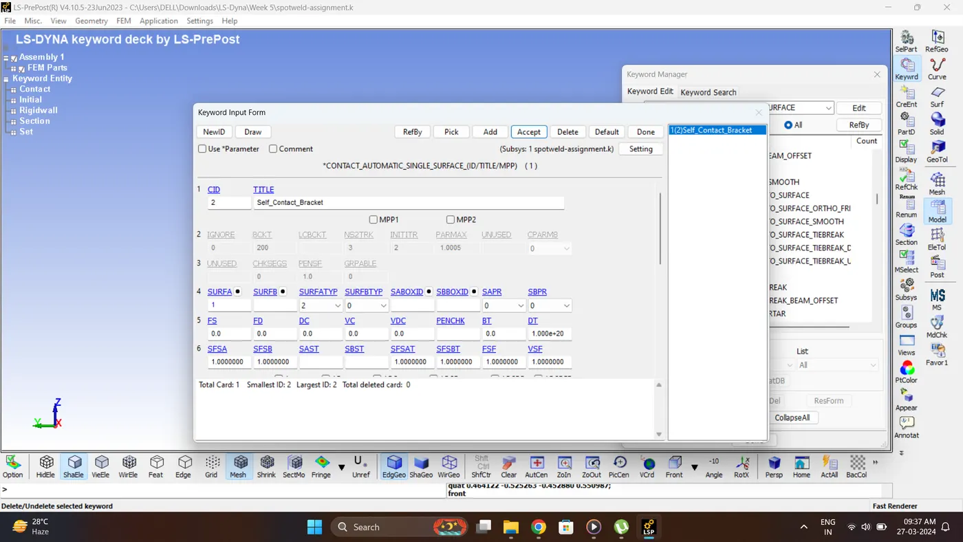
16. Create a Automatic single surface contact for bracket. Go to Model - Keyword manager - Contact - Automatic Single Surface.
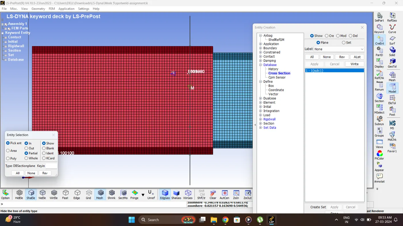
17. Create a Cross-Section to measure the sectional forces. Go to Model - Create entity - Database - Cross section.
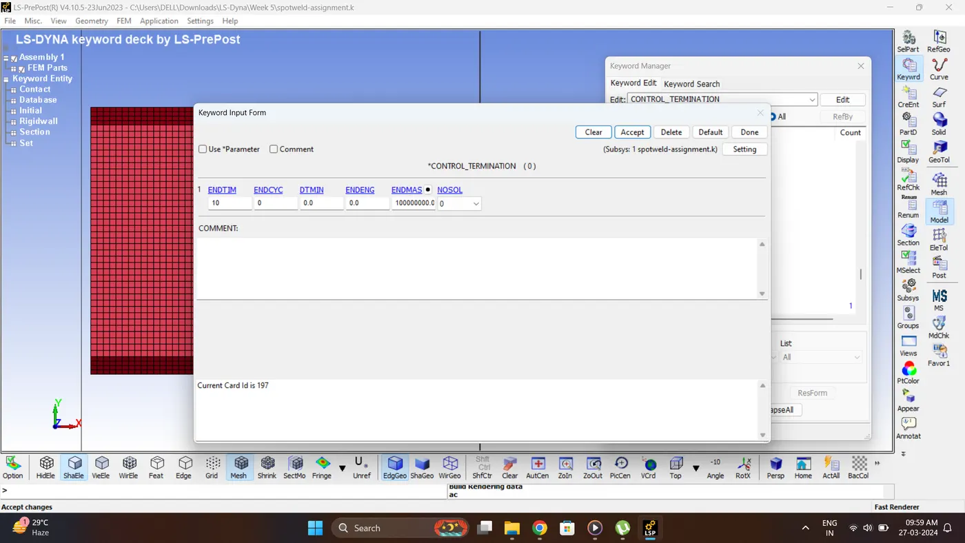
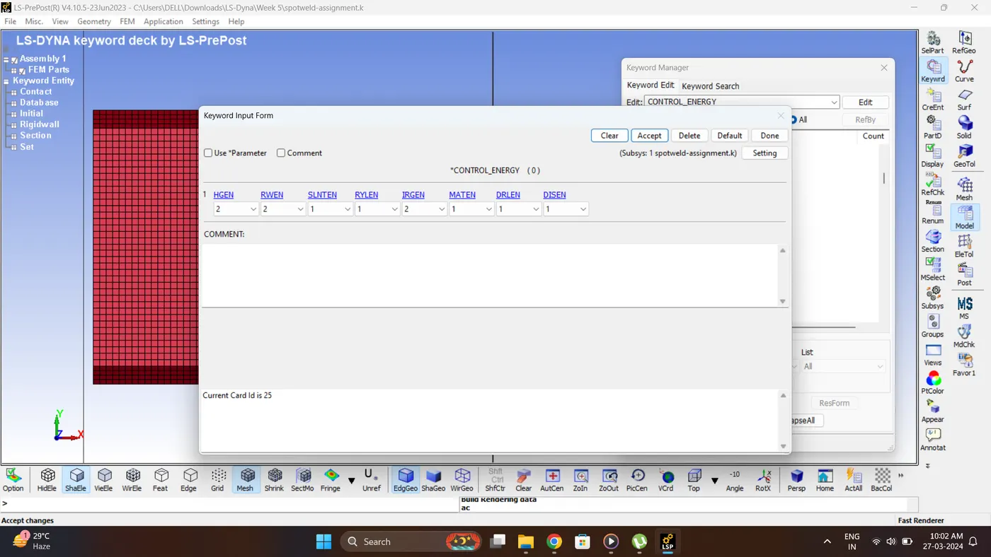
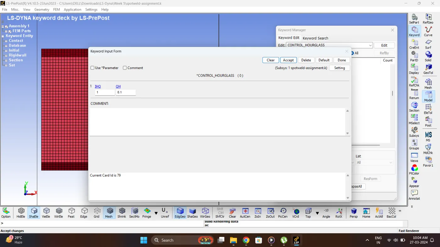
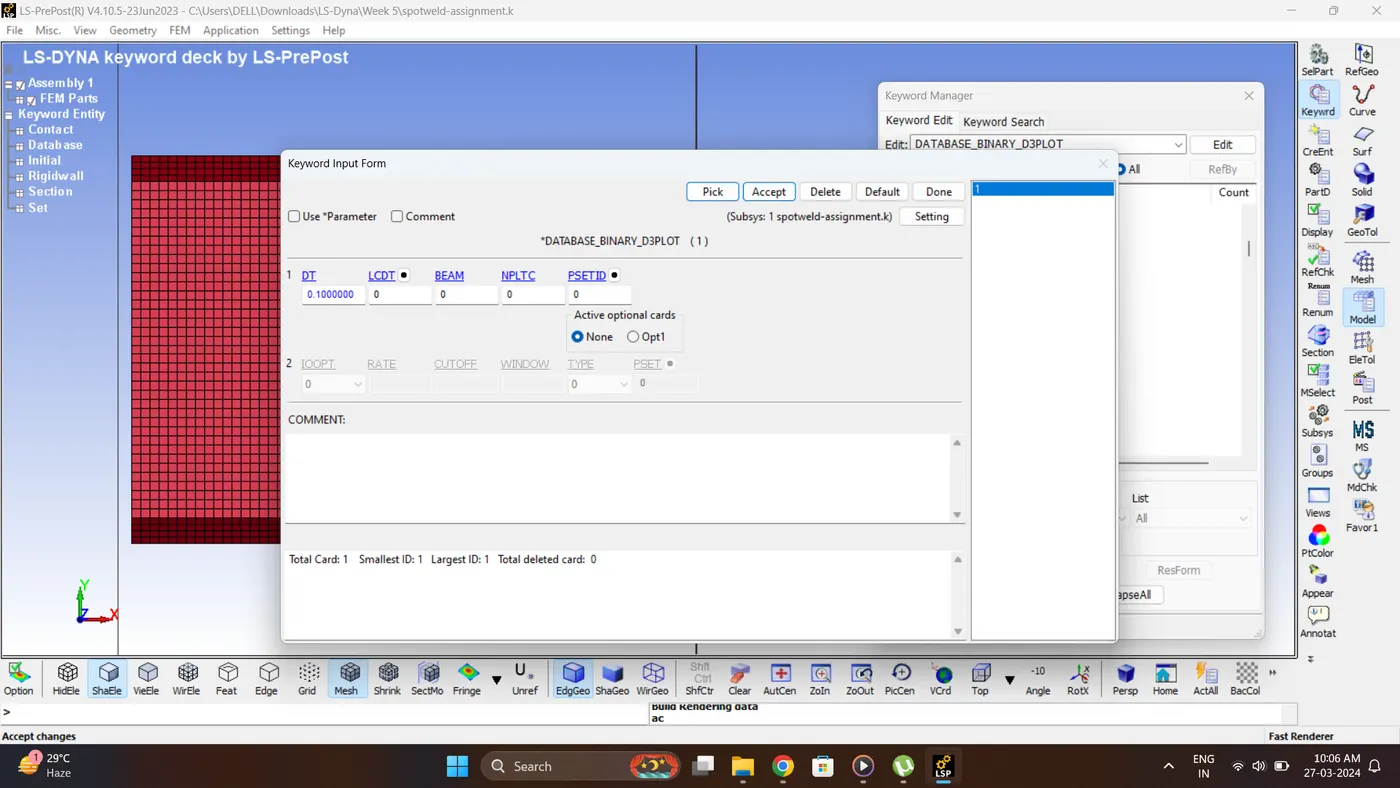
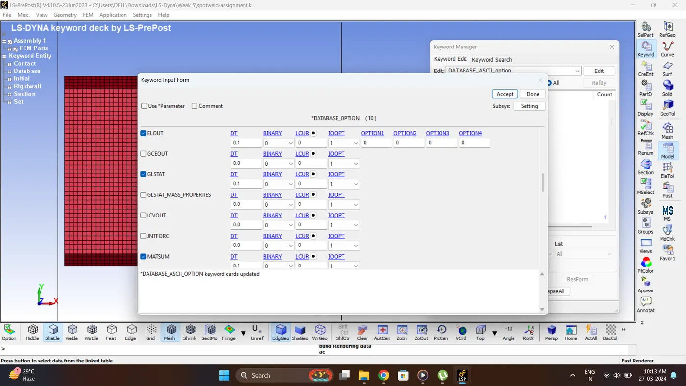
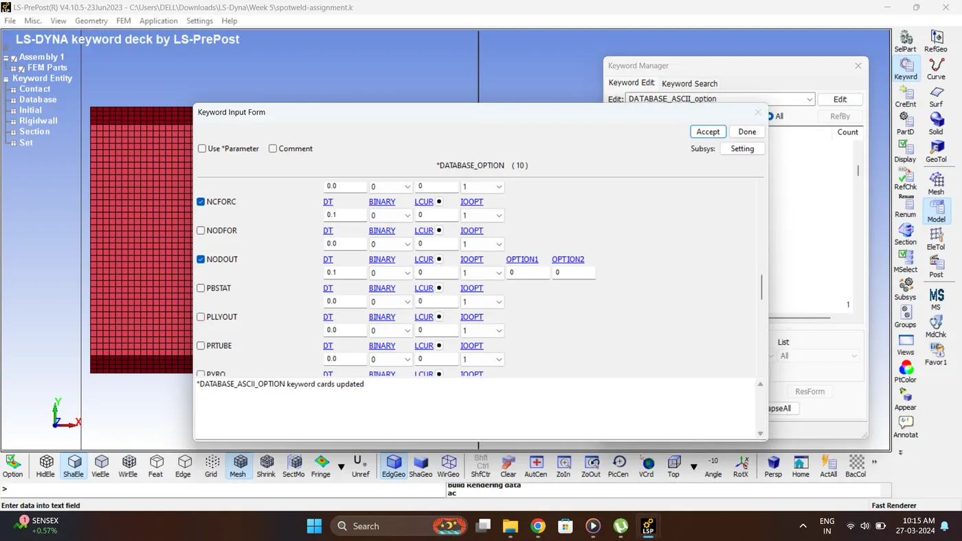
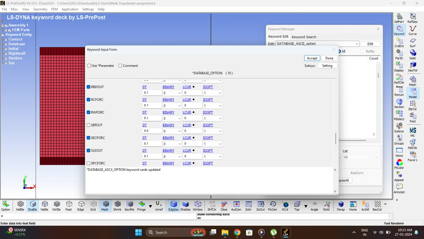
18. Create a required control and database card.
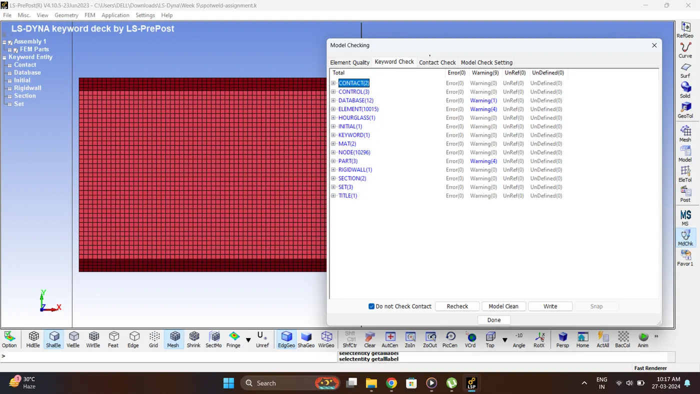
19. Run the Model Checker. Checke for any errors.
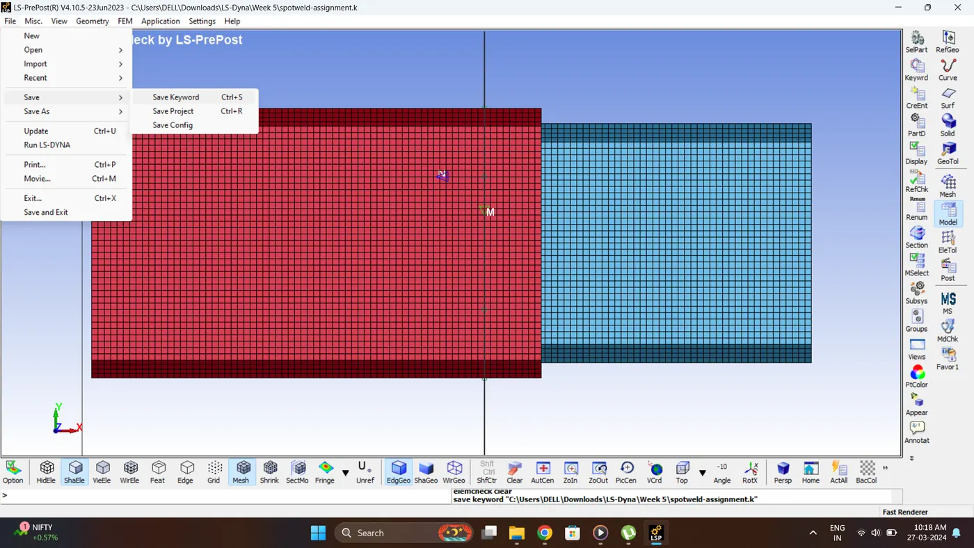
20. Save the Keyword File. Go to File - Save - Save Keyword.
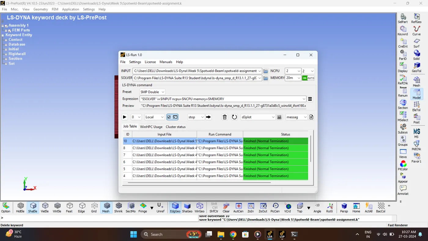
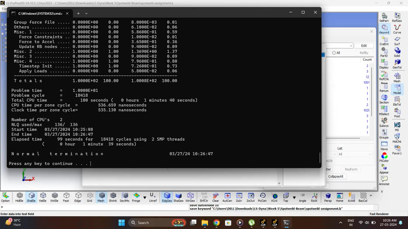
21. Run the Simulation. Open LS_Run - Select File - Click Add job to local queue.
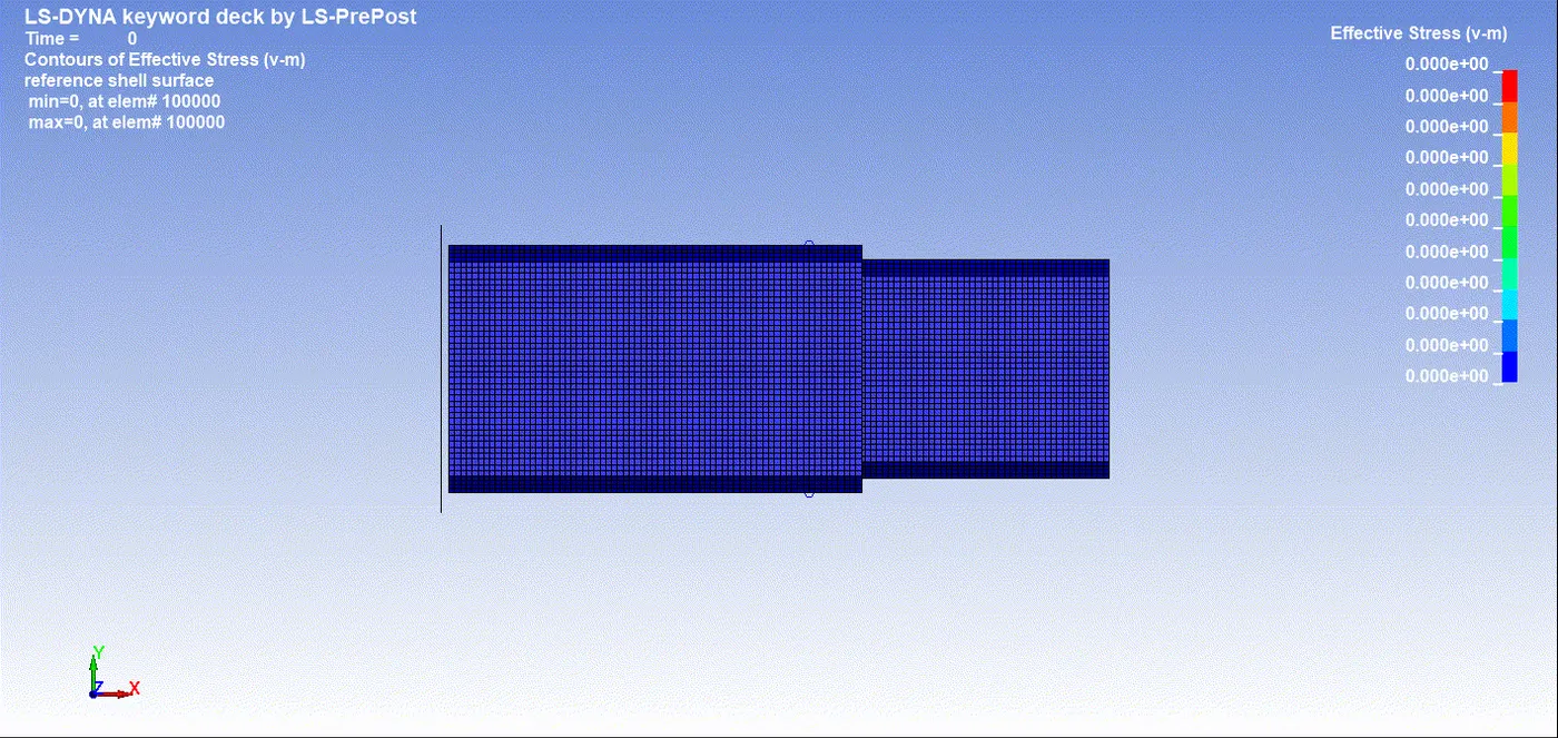
22. Open the Keyword and D3_plot in Ls-PrePost. Play the simulation and contour the von mises stress.
Max Vin mises stress = 278.052 gm/mm*ms^2.
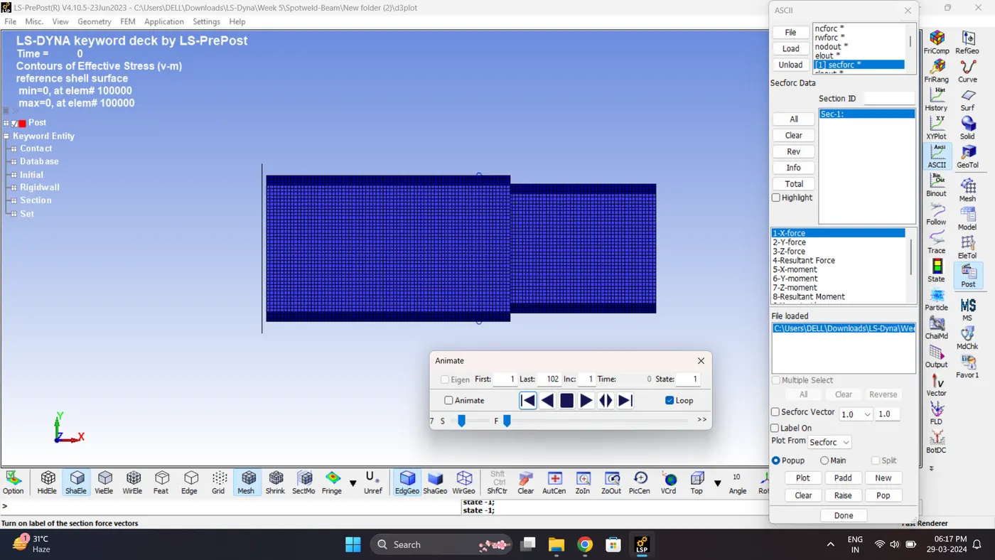
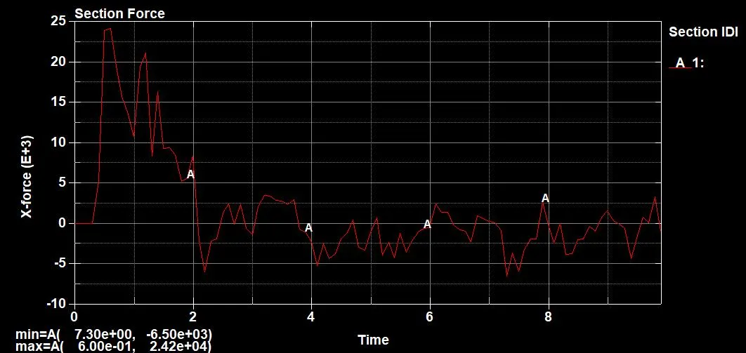
23. Plot the Cross-Sectional Force generated at the middle Section.
Maximum section force (X) = 2.42e+04 gm*mm/ms^2.
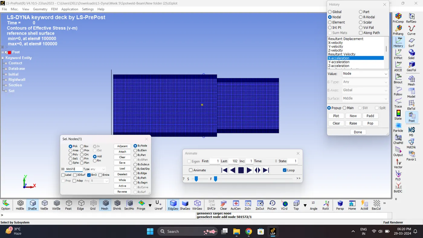
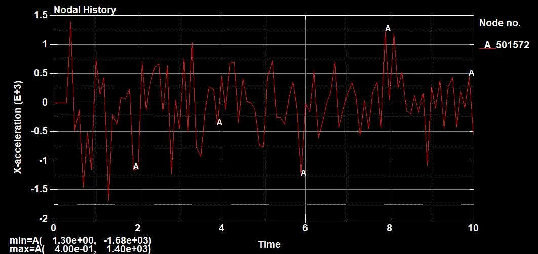
24. Plot the acceleration (X) of Node (Middle Node).
Max Acceleration = 1.68e+03 mm/ms^2.
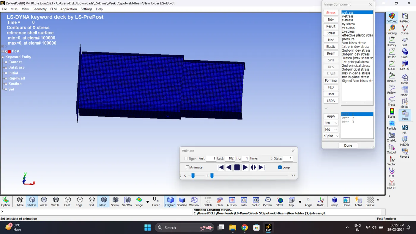
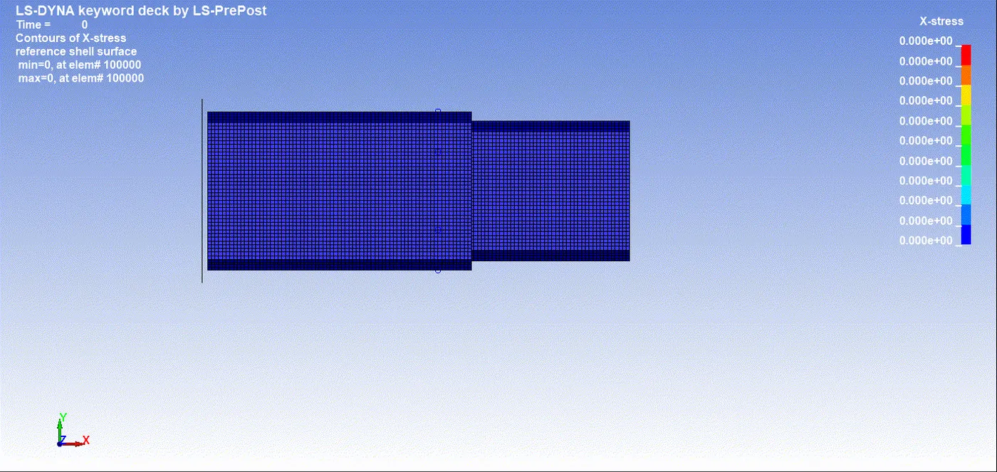
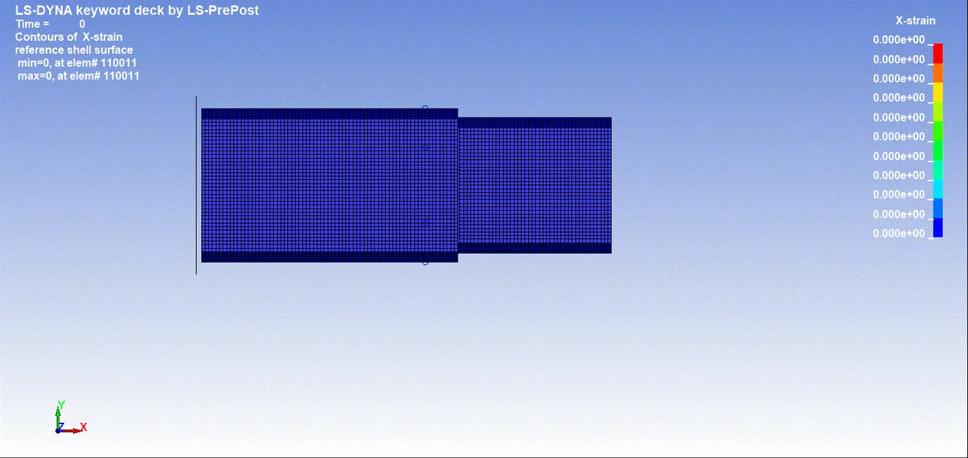
25.Plot the Maximum directional (X) stress and strain along the length.
Max Stress (X) = 296.543 gm/mm*ms^2.
Note: The maximum stress develop is in -X direction.
Max Strain (X) = 0
Since during crash the bracket doesn't go under any deformation.
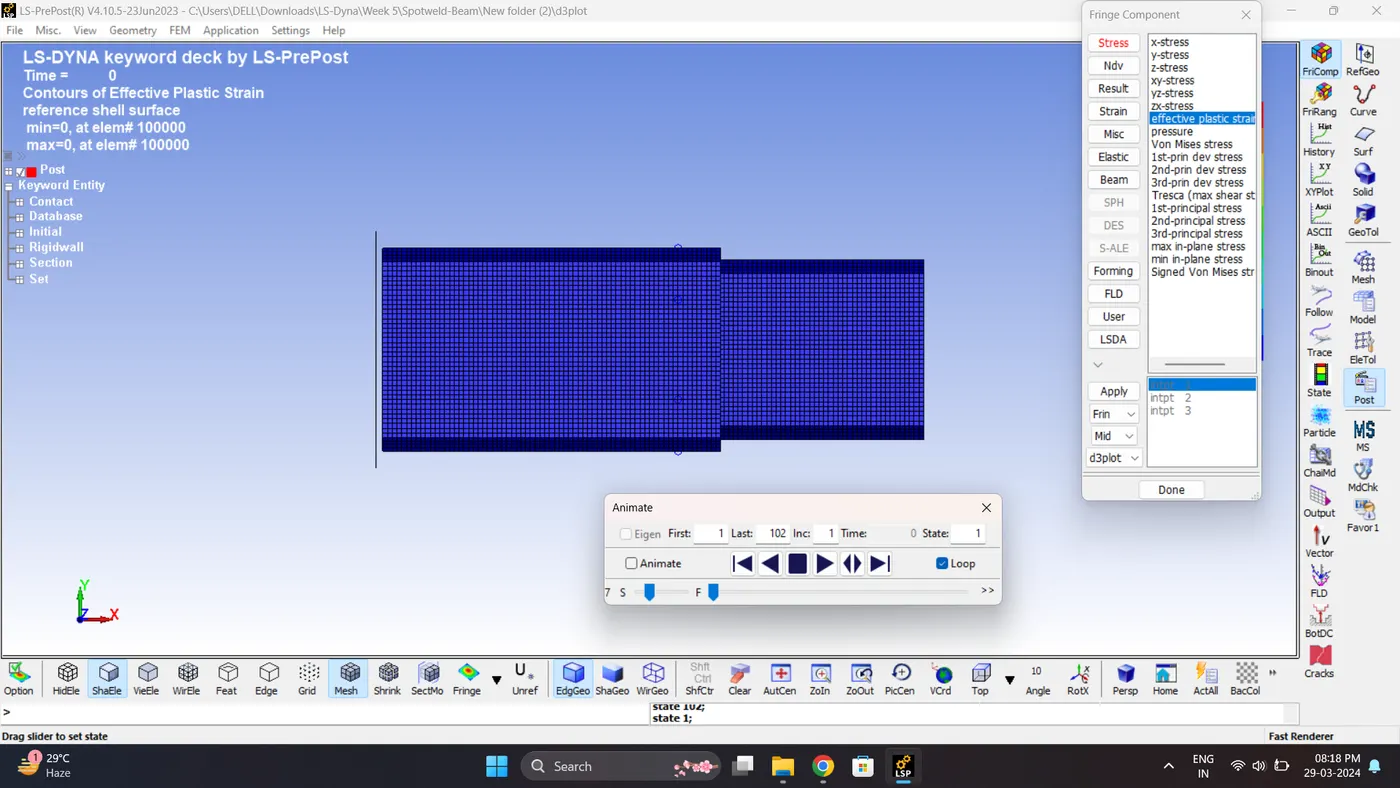
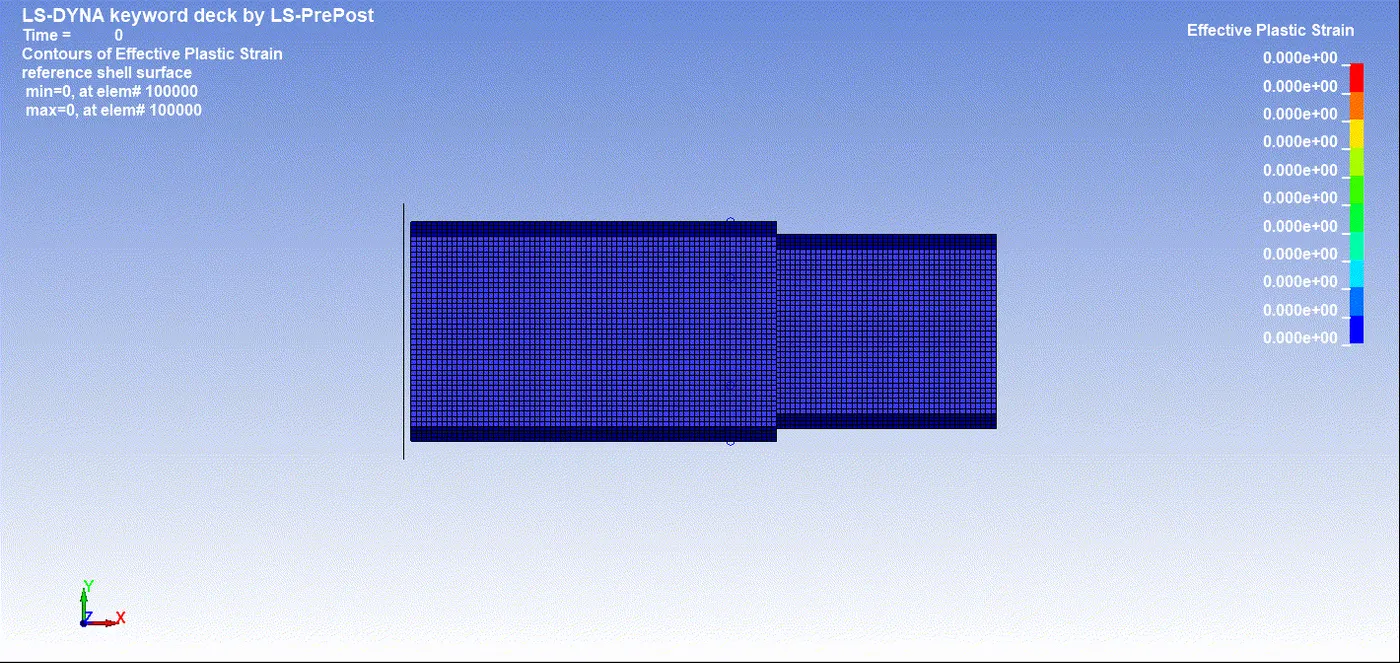
26. Plot the effective plastic strain.
Maximum Effective Plastic Strain - 0.1180
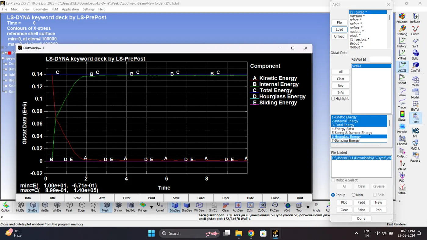
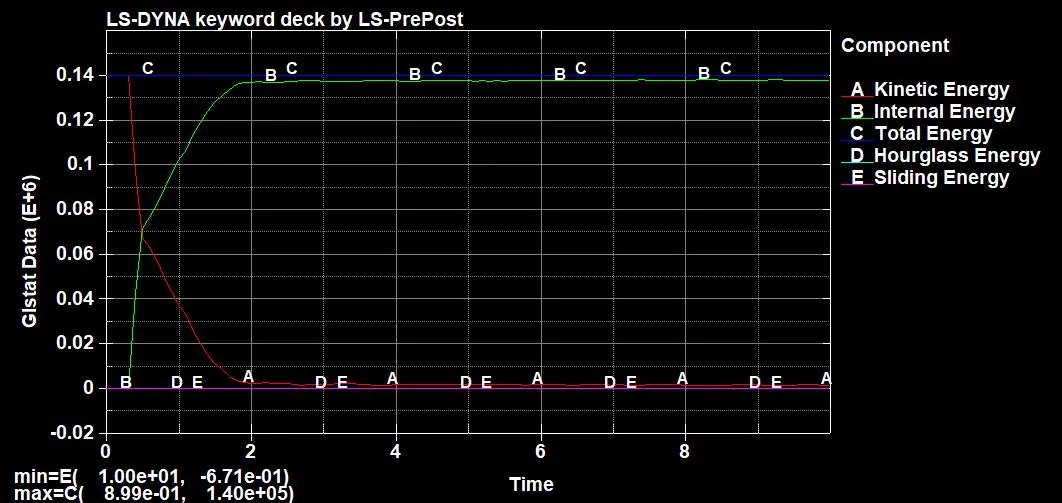
27. Plot all the energies.
| Sr.no | Name | Minimum | Maximum |
| 1 | Kinetic Energy | 1.47e+3 gm*mm^2/ms^2 | 1.40e+05 gm*mm^2/ms^2 |
| 2 | Internal Energy | 2.00e-20 gm*mm^2/ms^2 | 1.38e+05 gm*mm^2/ms^2 |
| 3 | Sliding Energy | -6.71e-01 gm*mm^2/ms^2 | 5.24e-01 gm*mm^2/ms^2 |
| 4 | Hourglass Energy | 0 | 0 |
| 5 | Total Energy | 1.40e+05 gm*mm^2/ms^2 | 1.40e+05 gm*mm^2/ms^2 |
| 6 | Stress (X) | 0 | 296.543 gm/mm*ms^2 |
| 7 | Strain (X) | 0 | 0 |
| 8 | Acceleration | 0 | 1.68e+03 mm/ms^2 |
| 9 | Section Force | 0 | 2.42e+04 gm*mm/ms^2 |
| 10 | Von Mises Stress | 0 | 278.052 gm/mm*ms^2. |
| 11 | Effective Plastic Strain | 0 | 0.1180 |
Case 2 (Spotweld-Hexa):
1. Delete all the Beam element cards.
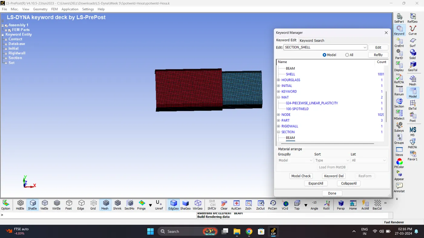
2. Create a Hexa Element. Before creating hexa element measure the deference between two component by aligning node parallel.
After measuring go to
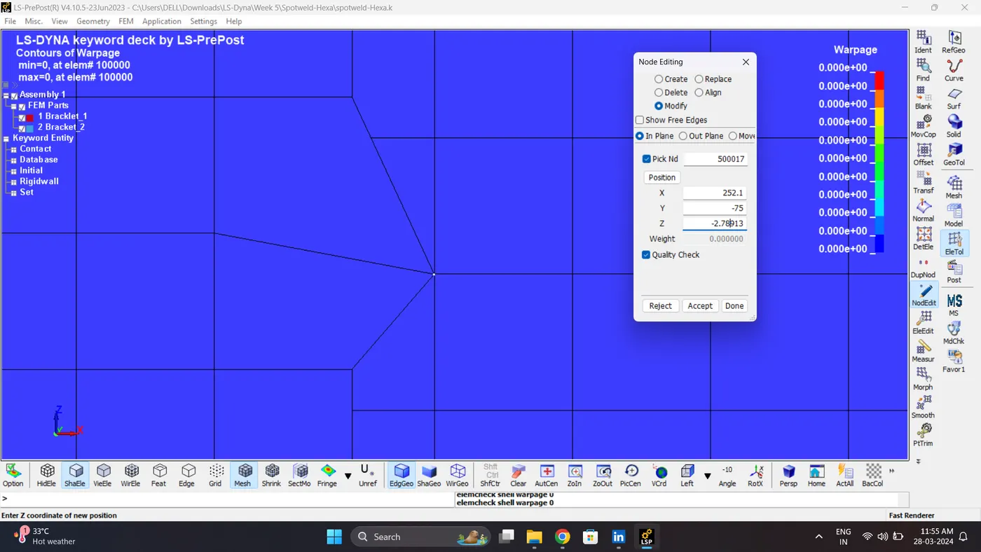
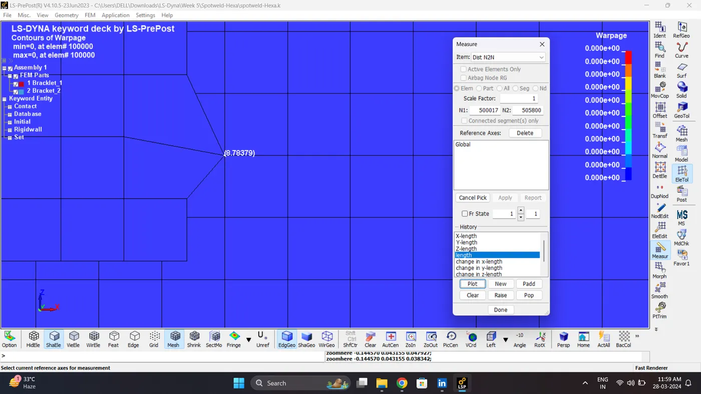
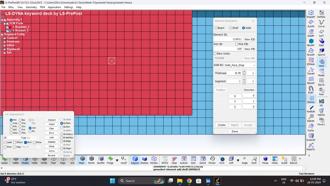
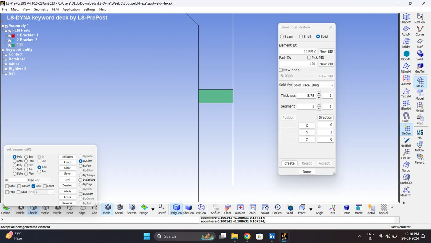
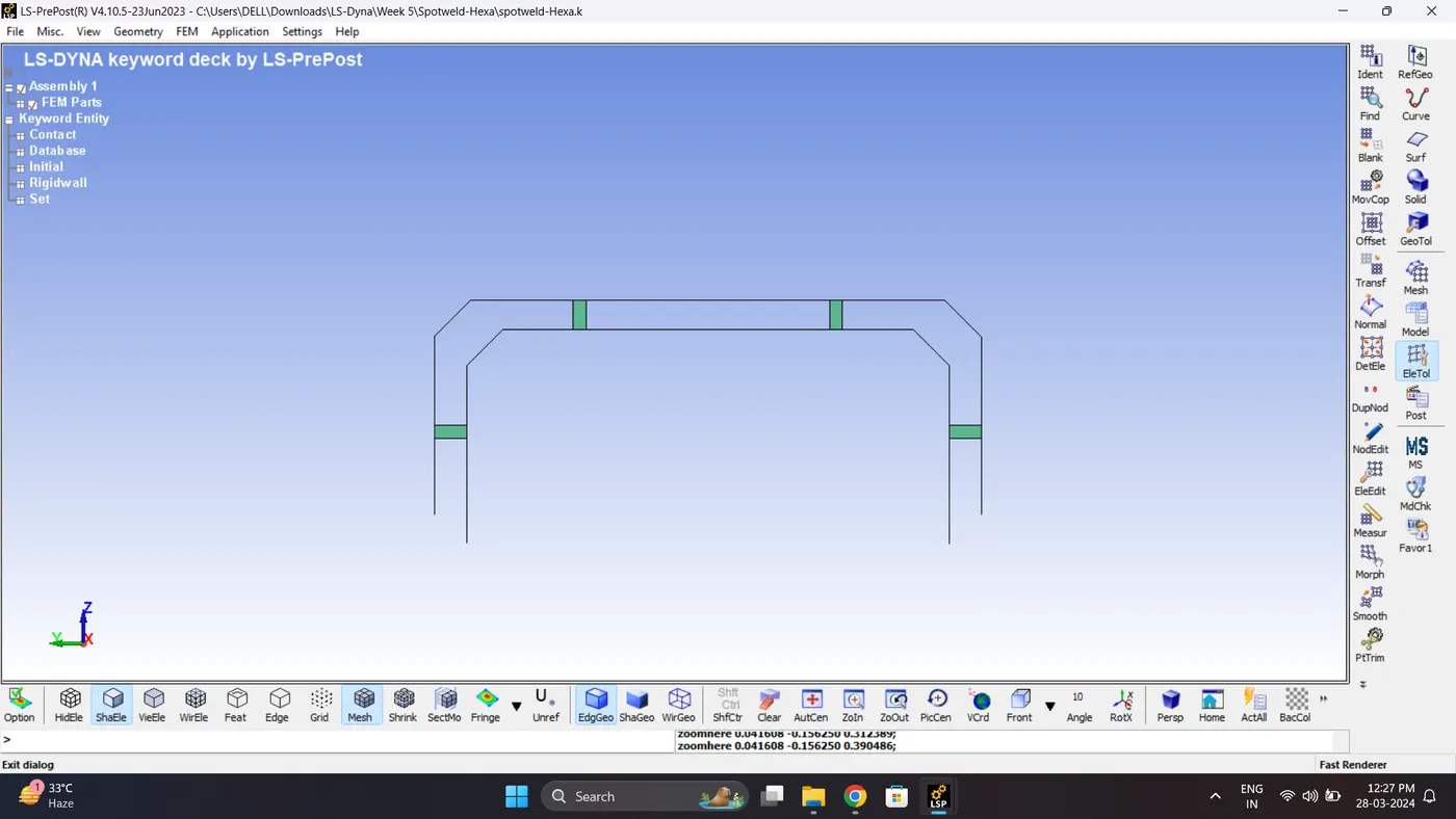
3. Create a section for Solid. Go to Model - Keyword Manger - Section - Solid.
Note: Keep the element formulation as 1 (It required for MAT 100).
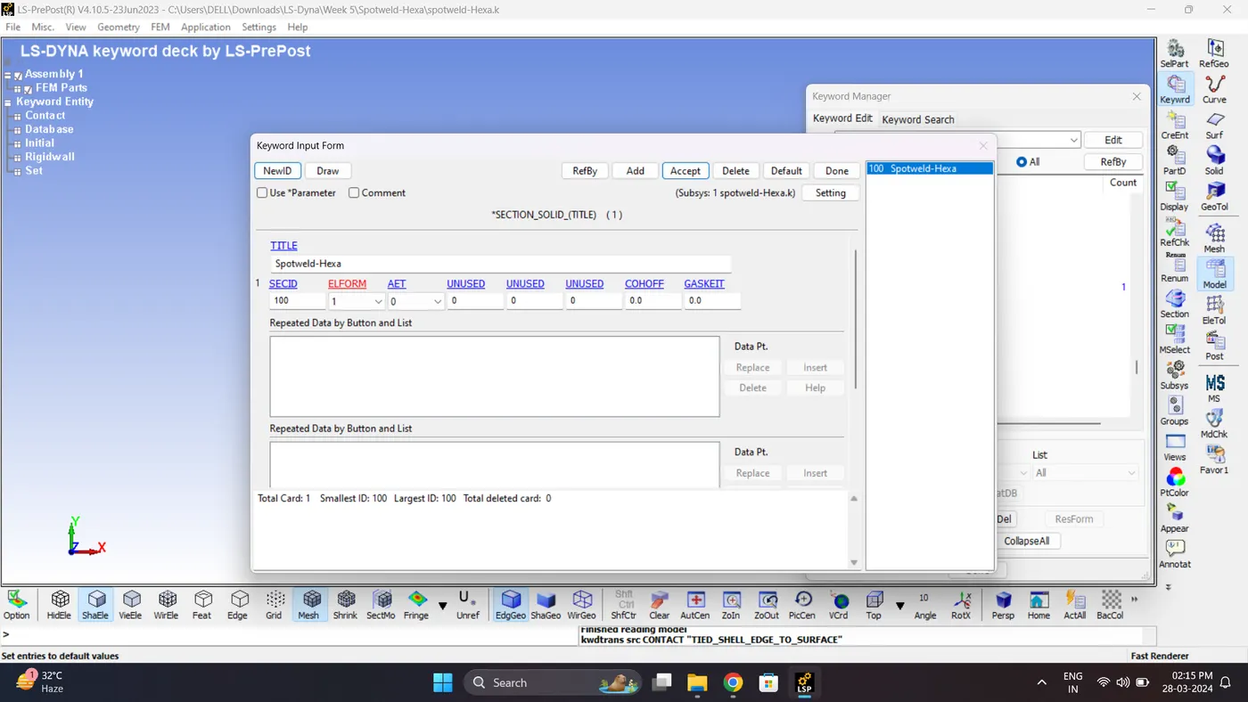
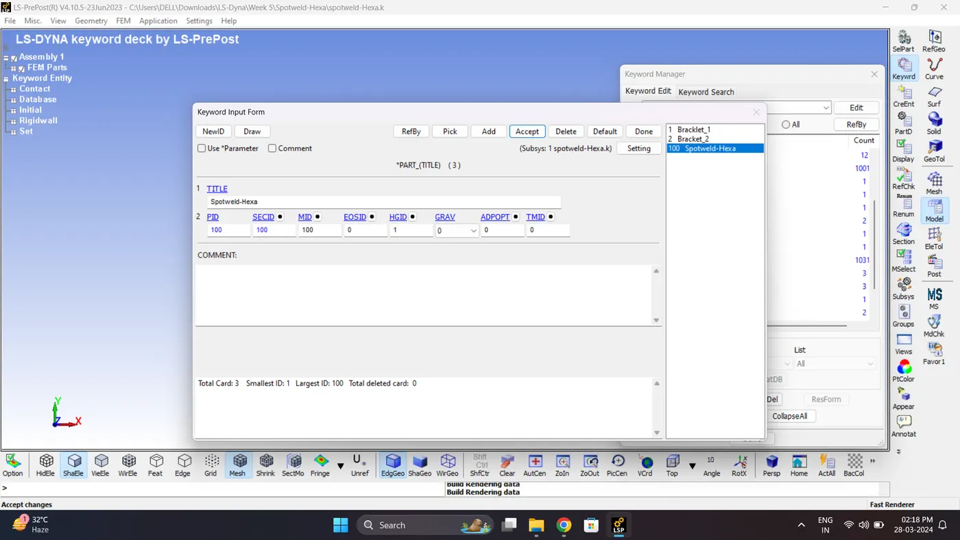
4. Assign section, Material, Hourglass to solid Part.
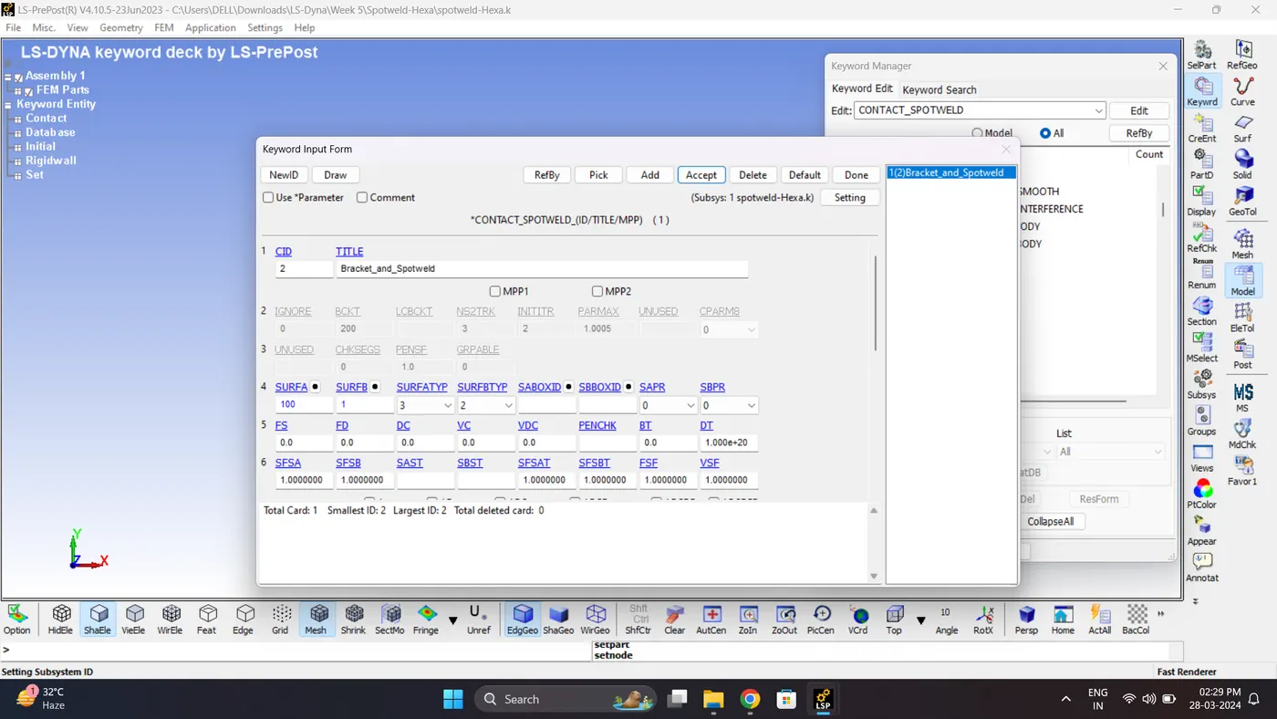
5. Create a Spotweld Contact. Go to Model - Keyword manager - Contact - Spotweld.
6. Save the Keyword File. Go to File - Save - Save Keyword.
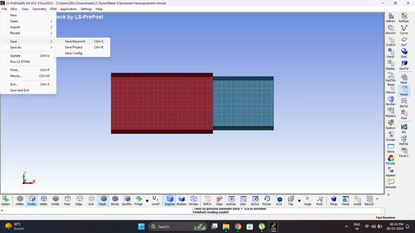
7. Run the Simulation. Open LS_Run - Select File - Click Add job to local queue.
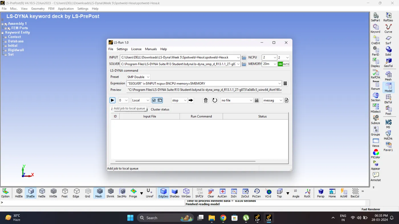
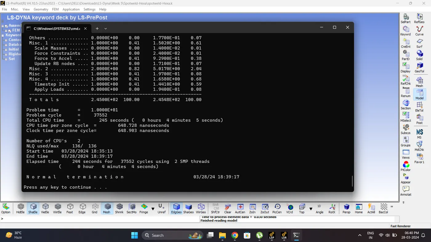
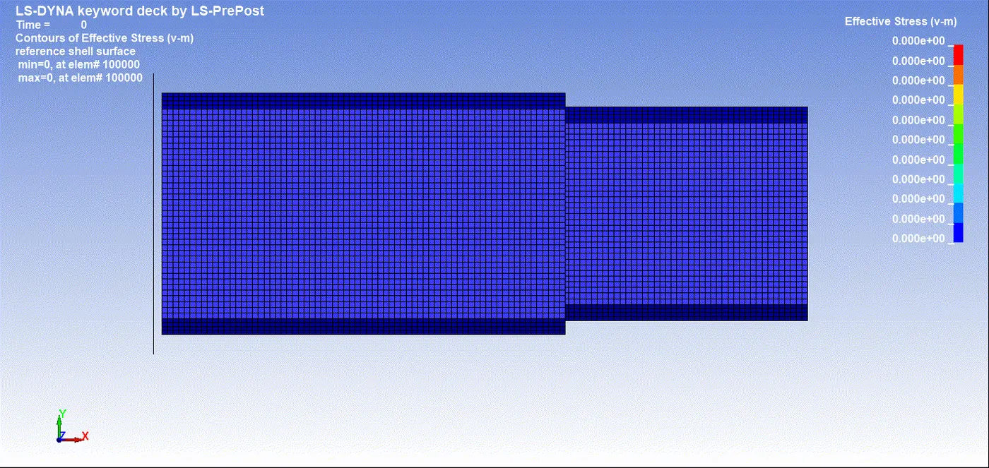
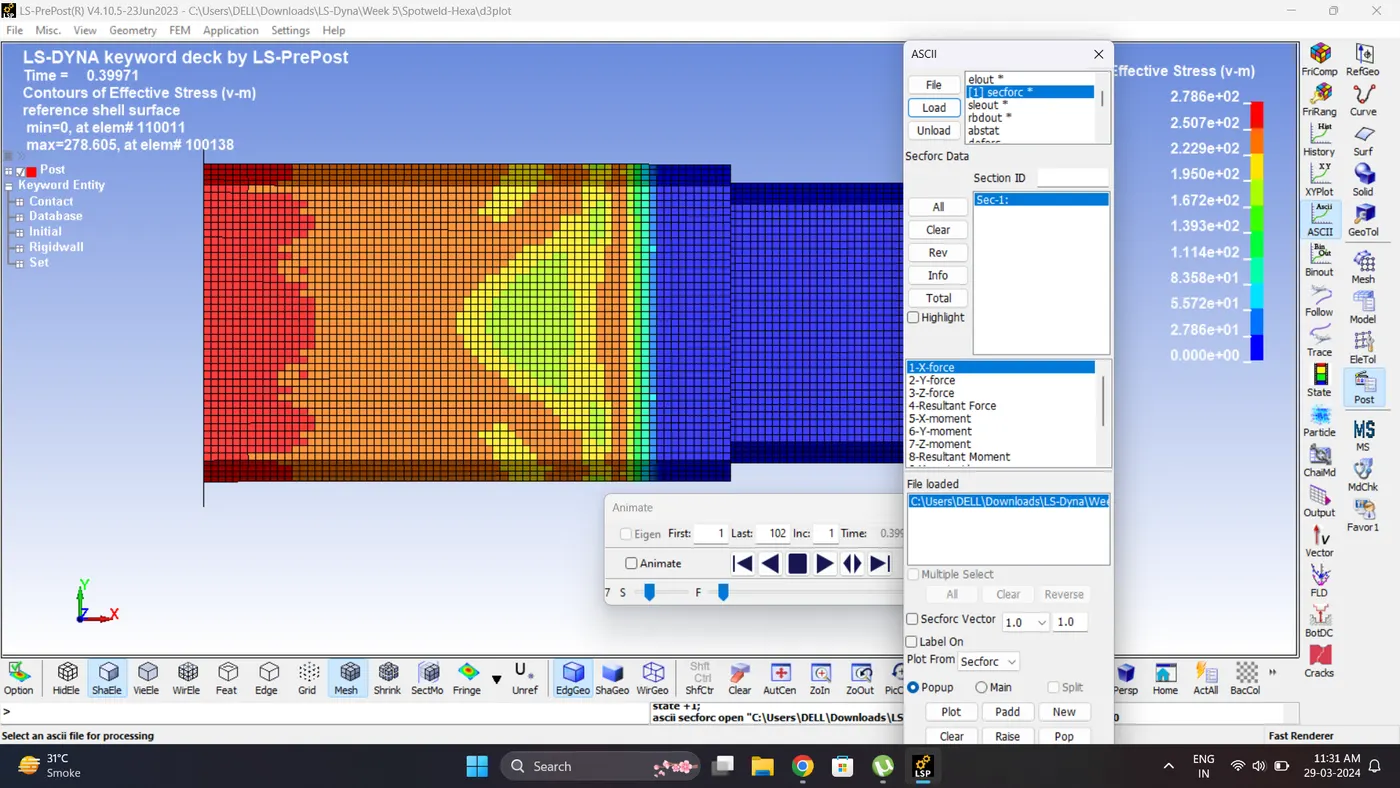
8. Open the Keyword and D3_plot in Ls-PrePost. Play the simulation and contour the von mises stress.
Max Vin mises stress = 278.605 gm/mm*ms^2.
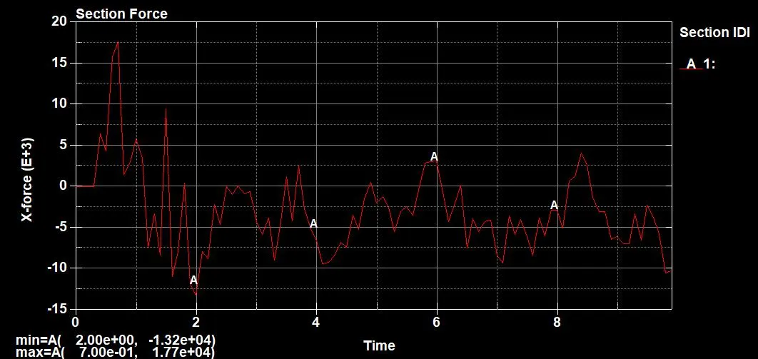
9. Plot the Cross-Sectional Force generated at the middle Section.
Maximum section force (X) = 1.77e+04 gm*mm/ms^2.
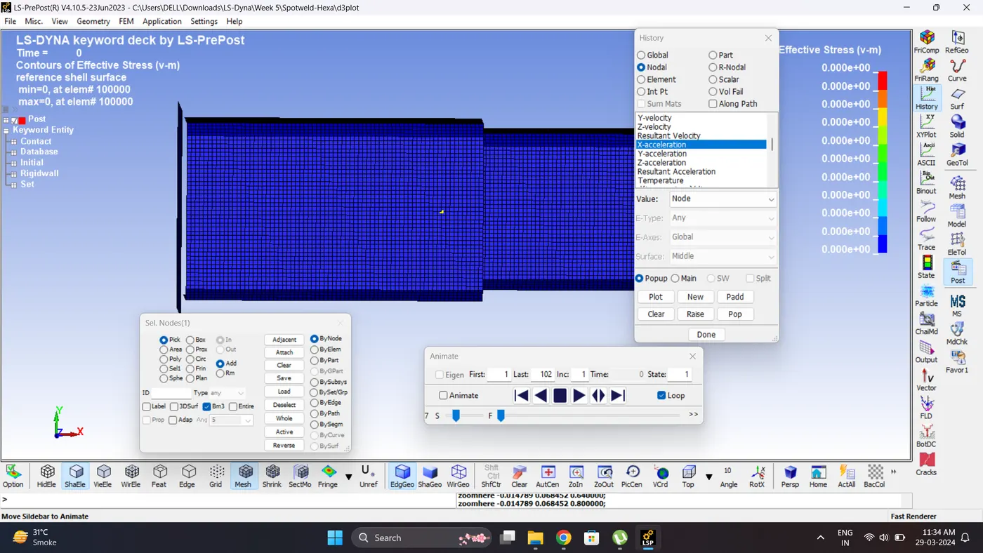
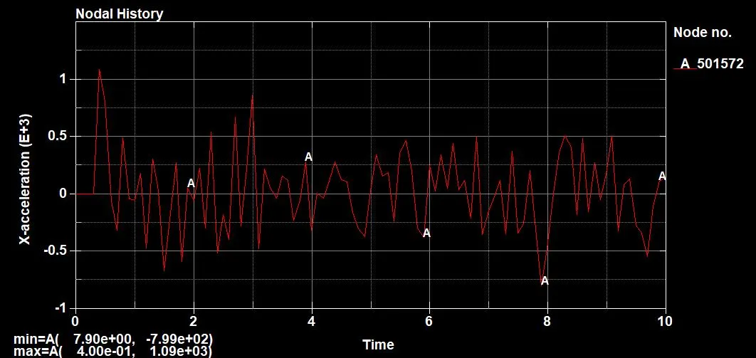
10. Plot the acceleration (X) of Node (Middle Node).
Max Acceleration = 1.09e+03 mm/ms^2.
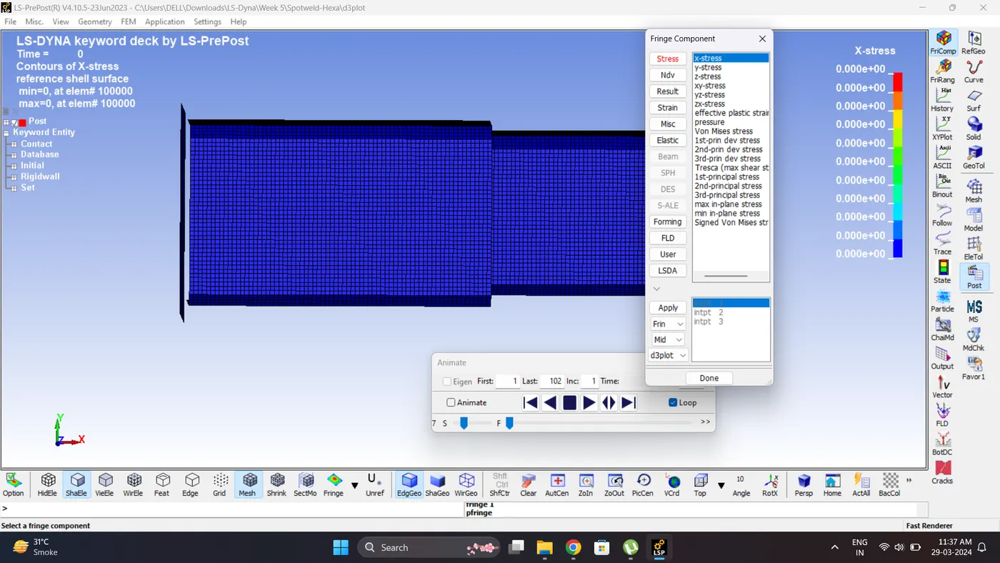
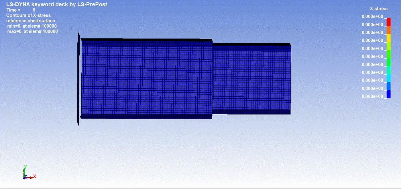
11. Plot the Maximum directional (X) stress and strain along the length.
Max Stress (X) = 286.241 gm/mm*ms^2.
Note: The maximum stress develop is in -X direction.
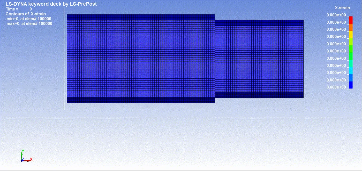
Max Strain (X) = 0
Since during crash the bracket doesn't go under any deformation.
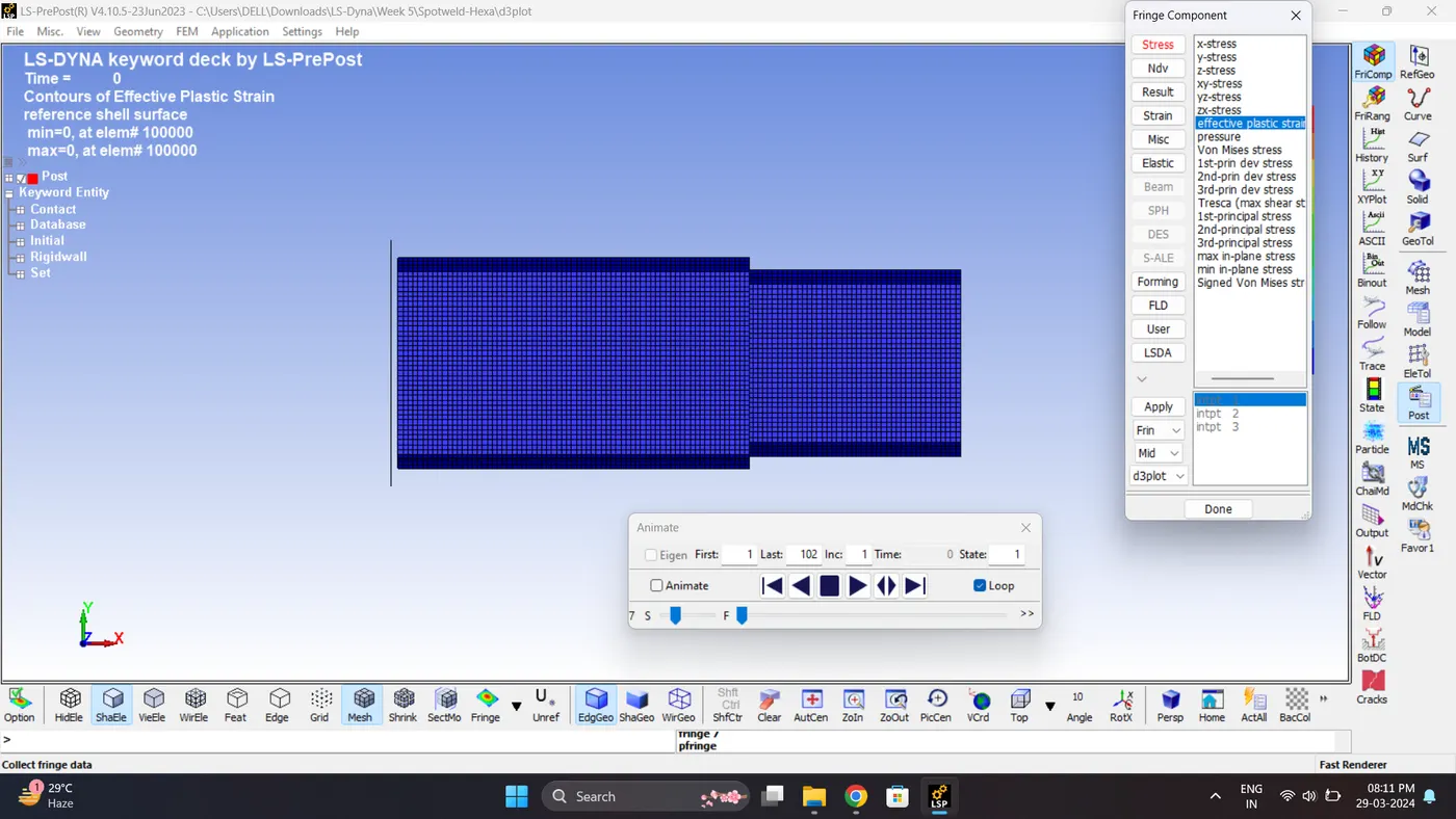
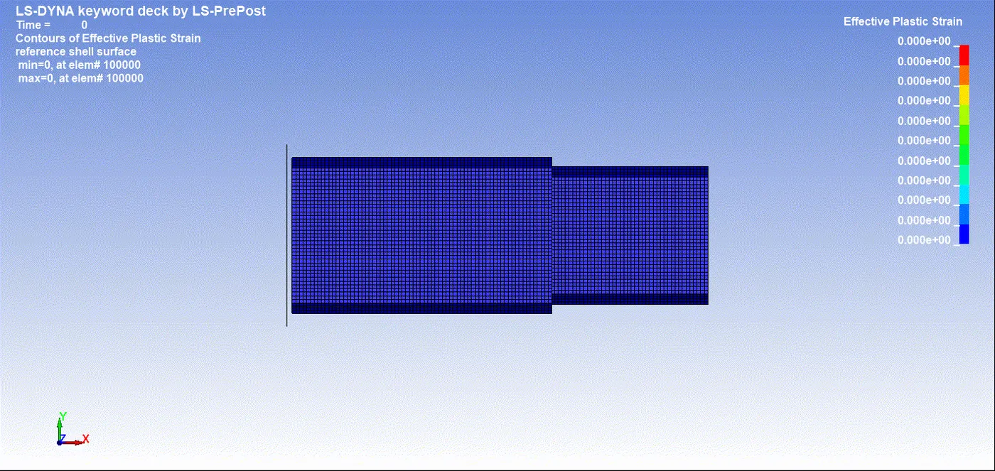
12. Plot the effective plastic strain.
Maximum Effective Plastic Strain - 0.6348
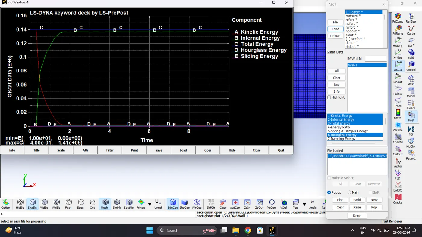
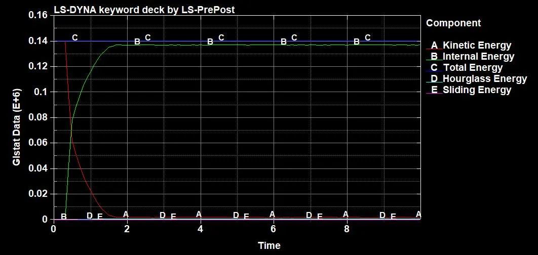
13. Plot all the energies.
| Sr.no | Name | Minimum | Maximum |
| 1 | Kinetic Energy | 1.64e+03 gm*mm^2/ms^2 | 1.41e+05 gm*mm^2/ms^2 |
| 2 | Internal Energy | 2.00e-20 gm*mm^2/ms^2 | 1.37e+05 gm*mm^2/ms^2 |
| 3 | Sliding Energy | 0 | 0 |
| 4 | Hourglass Energy | 0 | 9.01e+02 gm*mm^2/ms^2 |
| 5 | Total Energy | 1.40e+05 gm*mm^2/ms^2 | 1.41e+05 gm*mm^2/ms^2 |
| 6 | Stress (X) | 0 | 286.241 gm/mm*ms^2 |
| 7 | Strain (X) | 0 | 0 |
| 8 | Acceleration | 0 | 1.09e+3 mm/ms^2 |
| 9 | Section Force | 0 | 1.77e+04 gm*mm/ms^2 |
| 10 | Von Mises Stress | 0 | 278.605 gm/mm*ms^2. |
| 12 | Effective Plastic Strain | 0 | 0.6348 |
Comparison:
Case 1 (Spotweld-Beam)
| Sr.no | Name | Minimum | Maximum |
| 1 | Kinetic Energy | 1.47e+3 gm*mm^2/ms^2 | 1.40e+05 gm*mm^2/ms^2 |
| 2 | Internal Energy | 2.00e-20 gm*mm^2/ms^2 | 1.38e+05 gm*mm^2/ms^2 |
| 3 | Sliding Energy | -6.71e-01 gm*mm^2/ms^2 | 5.24e-01 gm*mm^2/ms^2 |
| 4 | Hourglass Energy | 0 | 0 |
| 5 | Total Energy | 1.40e+05 gm*mm^2/ms^2 | 1.40e+05 gm*mm^2/ms^2 |
| 6 | Stress (X) | 0 | 296.543 gm/mm*ms^2 |
| 7 | Strain (X) | 0 | 0 |
| 8 | Acceleration | 0 | 1.68e+03 mm/ms^2 |
| 9 | Section Force | 0 | 2.42e+04 gm*mm/ms^2 |
| 10 | Von Mises Stress | 0 | 278.052 gm/mm*ms^2. |
| 11 | Effective Plastic Strain | 0 | 0.1180 |
Case 2 (Spotweld-Hexa)
| Sr.no | Name | Minimum | Maximum |
| 1 | Kinetic Energy | 1.64e+03 gm*mm^2/ms^2 | 1.41e+05 gm*mm^2/ms^2 |
| 2 | Internal Energy | 2.00e-20 gm*mm^2/ms^2 | 1.37e+05 gm*mm^2/ms^2 |
| 3 | Sliding Energy | 0 | 0 |
| 4 | Hourglass Energy | 0 | 9.01e+02 gm*mm^2/ms^2 |
| 5 | Total Energy | 1.40e+05 gm*mm^2/ms^2 | 1.41e+05 gm*mm^2/ms^2 |
| 6 | Stress (X) | 0 | 286.241 gm/mm*ms^2 |
| 7 | Strain (X) | 0 | 0 |
| 8 | Acceleration | 0 | 1.09e+03 mm/ms^2 |
| 9 | Section Force | 0 | 1.77e+04 gm*mm/ms^2 |
| 10 | Von Mises Stress | 0 | 278.605 gm/mm*ms^2. |
| 11 | Effective Plastic Strain | 0 | 0.6348 |
It is seen from the above results, Due to change in element type of spotweld
- Acceleration after impact of bracket in beam element is more, due to beam element restrict on 2 node but in hexa it restrict more node and element.
- Section forces developed in the middle of the shell component are more in beam element spot welds contrary to solid element spot welds.
- Stress along the length of the model are more as well for beam elements.
- Since there are no deformation along the length in both the cases strain value remains 0.
- Both case weld are modelled with steel properies and that why they are behaving in a elastic manner.
Conclusion:
Model spotwelds for the given assembly of parts and run a crash test are run successfully.