Week - 5 - Modelling Spotwelds
MODELLING SPOTWELDS USING 1D BEAM AND 3D HEXA SOLID ELEMENTS
WEEK - 5, LS-DYNA
Objective:
- To create a crash simulation by connecting the 2 shell element using beam & solid (hexa) elements which are represented as spotwelds.
- Compare the results in both cases.
Procedure :
Case 1:
1. Import:
- Import the keyword file using LS - Prepost.
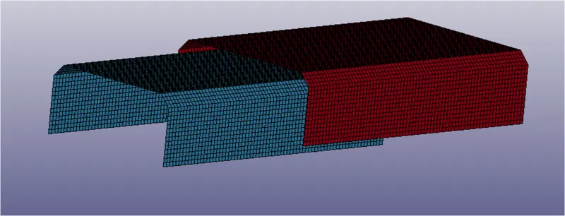
Imported Model
2. Create Material and Section Card:
- There are two components present in this model. Create a material card and section card and later assign these properties to the 2 parts in PART keyword.
- I have used steel properties and Element form 16 which are fully integrated shell elements for high accuracy.
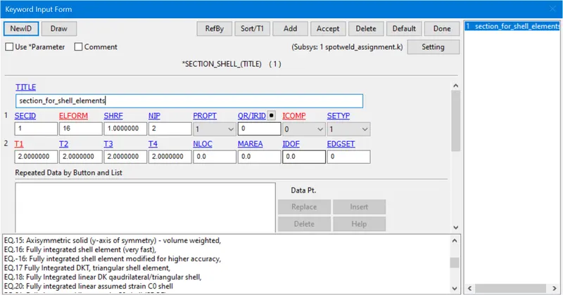
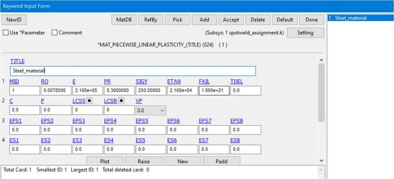
Section-Card Material-Card
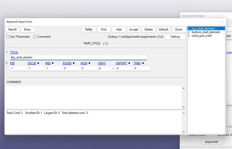
Assigned Section and Material properties to top and bottom parts
3. Creating Spot Welds:
- Here spot welds are represented as BEAM elements. I have created 8 spotwelds using Mesh >> Element Generation>>Beam option as shown below.
- Pick two nodes and accept
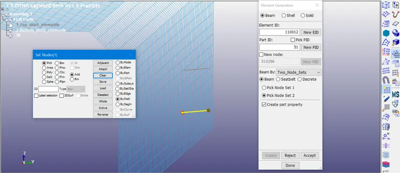
Creating Beam Element
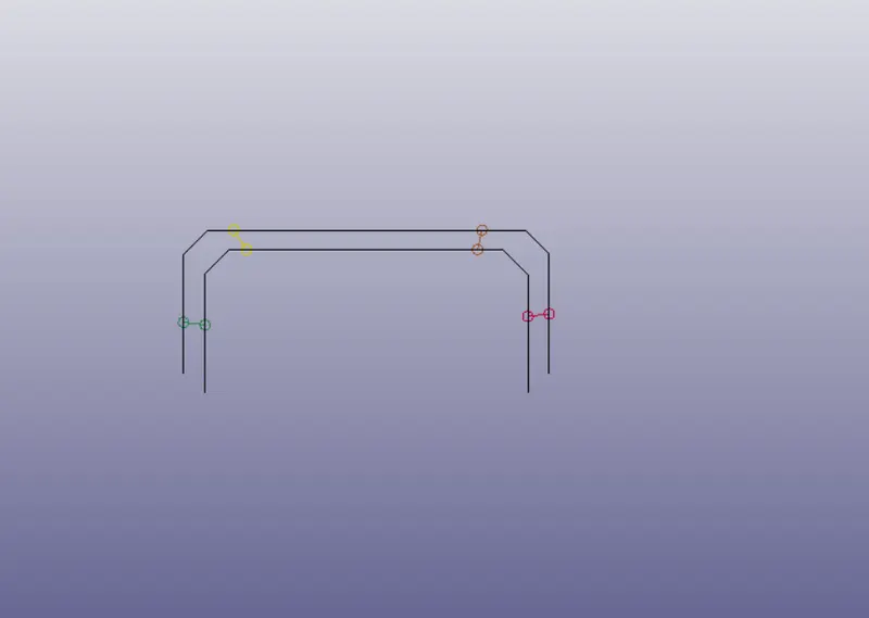
8 Spot welds are created
4. Material and Section cards for beam elements
- MAT_SPOTWELD - is material card for the spot weld beam elements.
- SECTION_BEAM - is section card for the spot weld beam elements.
- I have created same material id (MID) for spot welds as 100.
- We wanted the weld elements to fail during the simulation, we will set the TFAIL value as 2.5 ms which is half the TERMINATION time (5ms) of simulation.
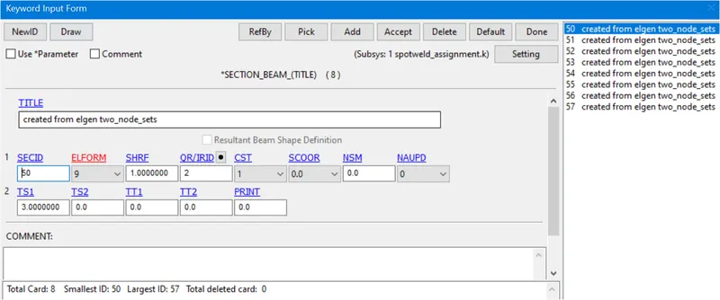
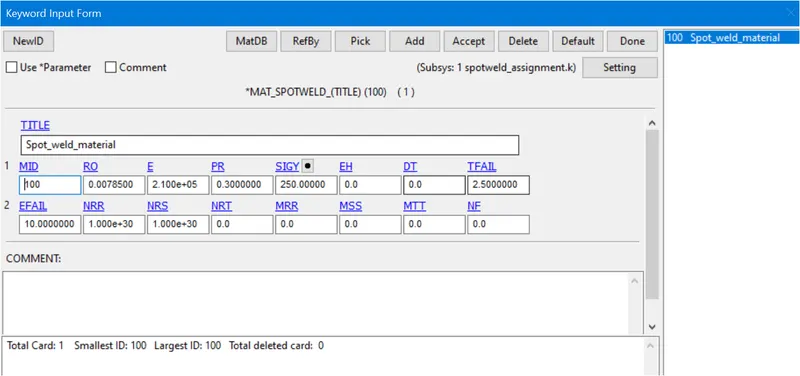
Section for spot weld Material for spot weld
Assigning Material and section for beam elements
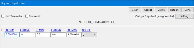
Control Termination card
5. Contacts:
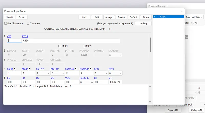
- Now we need to define appropriate contacts between the beam elements and the two parts which are connected to beam elements,
- this contact is given keeping beam elements as the slave and the two brackets shell elements as master as shown below using part set ID.
- AUTOMATIC SINGLE SURFACE is created using part ID where one part acts as a slave and other part as a master. This contact defines avoids penetration between the 2 parts when they come in contact during the simulation.
6. Creating Initial Velocity & Rigid Wall :
- A rigid wall planar is created in-order to mimic a crash simulation.
- An initial velocity 7.5 is given to all the shell elements in the direction of rigid wall.
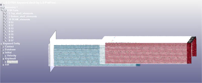
Preview of rigid wall and velocity
CASE 2:
7. Create Solid Hexa spot welds
- We can apply some changes to the file in case 1 and remaining properties will remain same
- In this 2nd case, we are going to model the spot welds as solid Hexa elements.
- First delete all the 8 beam elements and replace them using 8 solids Hexa elements.
- The Hexa elements are created using the element creation option under the EleTool button.
- use the options as shown below.
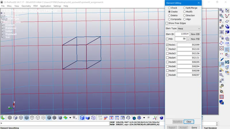
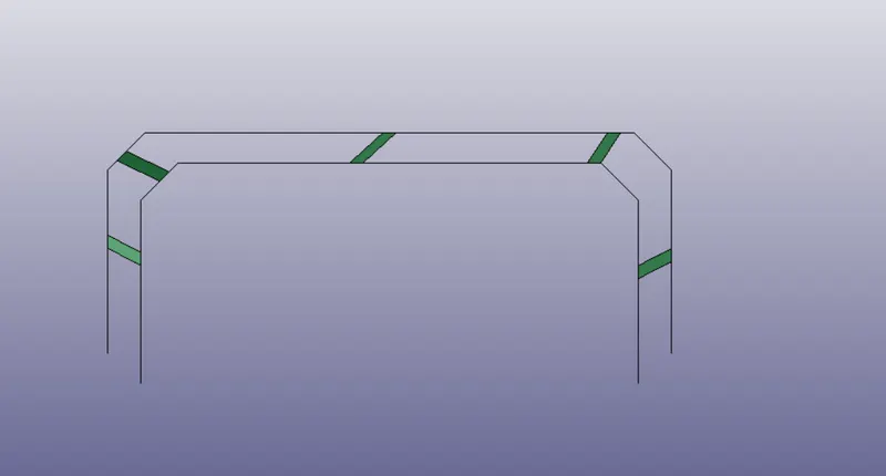
- Hexa elements are created successfully, now we can use the existing material cards and assign them to these solid hexa elements. Also, delete the section which is created for beam and replace it with a new solid section with ELEFORM 1 and assign it to the solid hexa elements,
- We should changes the contacts in this case 2. Use CONTACT_SPOTWELD card which defines spotweld connection for solid elements. All the remaining settings are same as in case 1.
8. Comparison of Results for CASE 1 & 2:
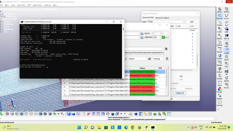
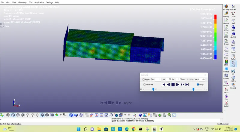
A. Simulation of case 1:
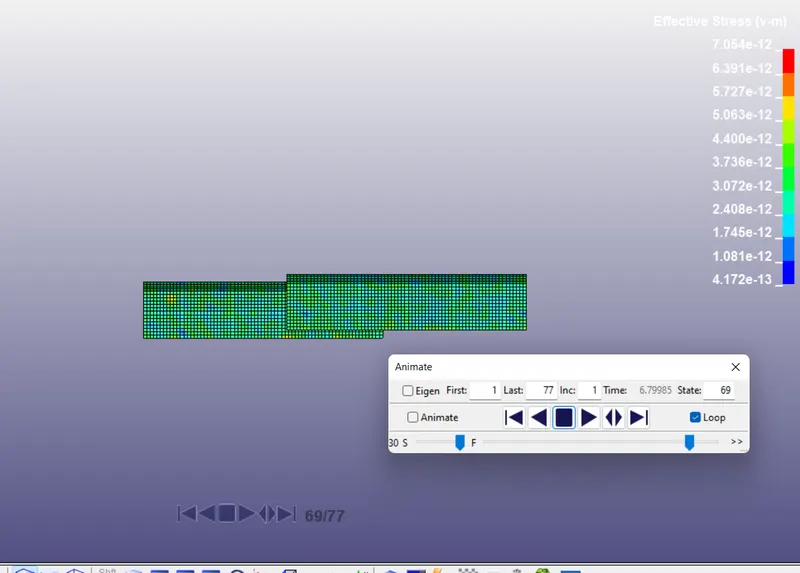
B. Simulation of case 2:
C. AXIAL AND SHEAR FORCES:
Case 1 Case 2
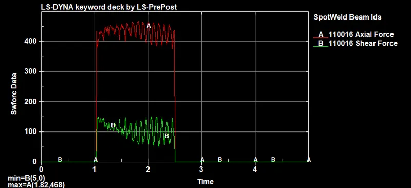
- From the above observations we can see in case-1 (beam elements), shear force rises at 1 ms and after the impact at 2.5 ms beam elements are failed and it stabilizes.The maximum here is near to 150. whereas axial force has higher values of nearly 468.
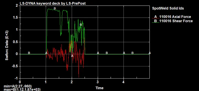
- Now, in case 2 shear force rises from 1ms and reaches upto 1.80. Here axial force drops to -1.12 and fluctuates upto 2.5 ms and stabilizes.
D. Acceleration Plot:
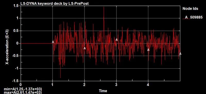
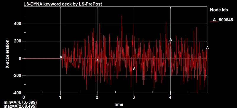
- I have selected the same nodes. you can see the plot looks similar as the fluctuations start and end at the same time but the ranges of miminum and maximum values are different
E. Energy Plot:
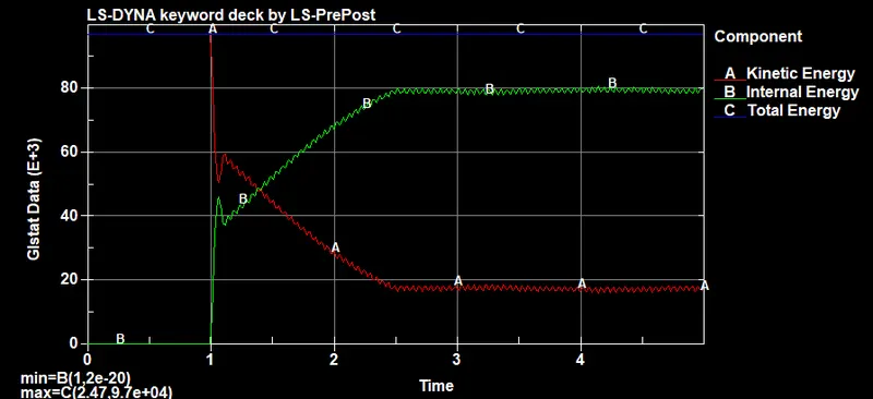
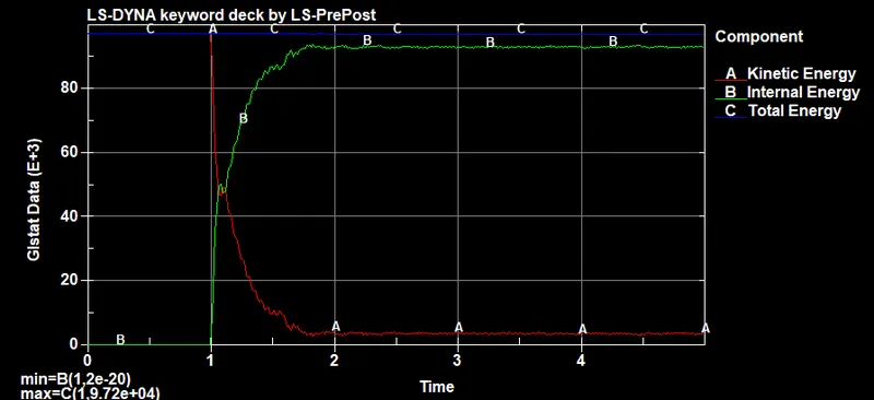
- we can see that kinetic energy decreases, the internal energy increases in both the cases as expected from the theory. The other important thing to be considered is that the total energy of the simulation remains constant.
F. Effective Plastic Strain:
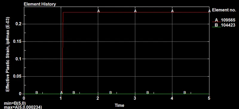
- EPS for the beam element 109565 is 0.000234
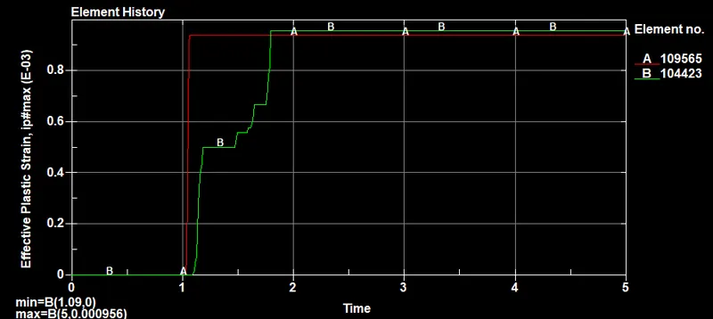
- EPS for the solid element 109565 is 0.00095
Conclusion:
- All the objectives are fulfilled. Spot welds are created using 1d beam elements and hexa solid elements respectively.
- From the above results we can hexa elements were more stiffer which inturn transfers more force during the simulation.
- Post-processing is also done successfully using D3plots and ASCII outputs.