Week - 5 - Modelling Spotwelds
Modelling Spotwelds
AIM:
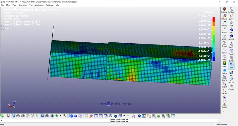
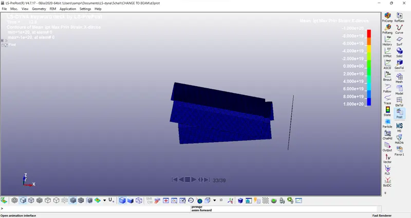
In this assignment, you will model spotwelds for the given assembly of parts and run a crash test similar to the one in assignment 4. Details about spotweld location is in the image below. The yellow line signifies the spotweld directions. You need to use 3-7 spotwelds along this line, in a symmetric manner, before running the simulation
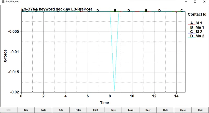
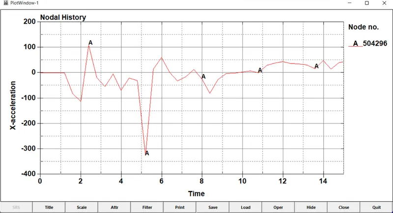
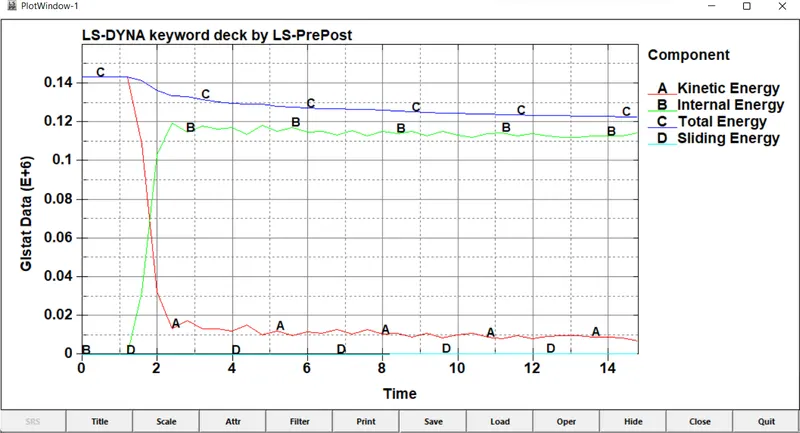
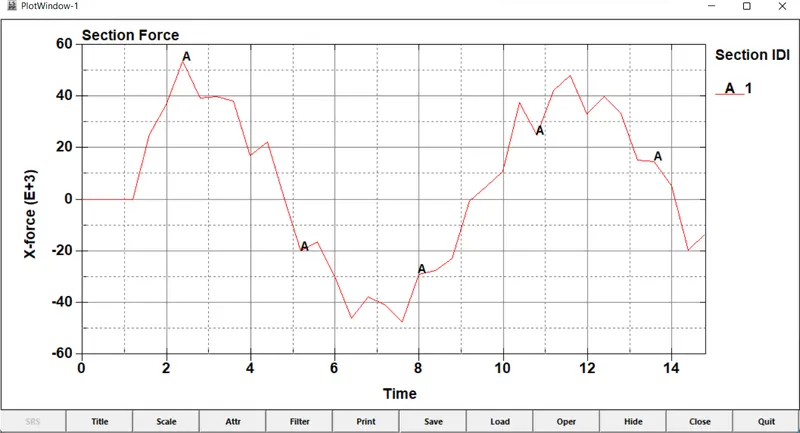
The spotwelds should be modeled using beam elements and solid elements separately. While using solid elements, one spotweld should have one solid element. The axial and shear force should be compared among beam and solid elements. The same material card using *MAT_SPOTWELD should be used for both beam and solid elements. You can use steel material data for *MAT_SPOTWELD cards and calibrate the failure data according to your results. The best simulation should have a failure at half of the termination time.
- Download the file and open in LS-dyna
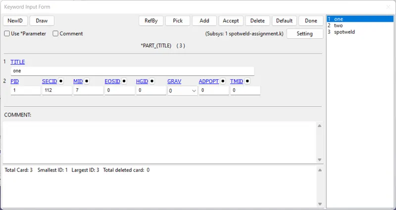
- Rename the part name
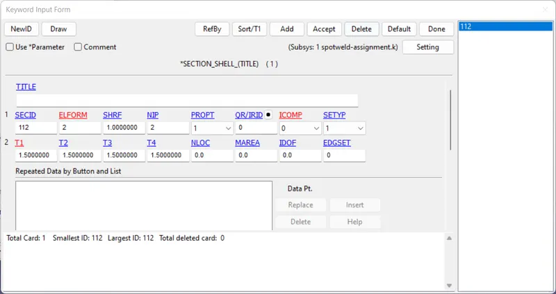
- Assigne the section as 'shell'
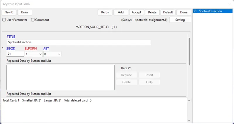
- For 'solid' in spotweld
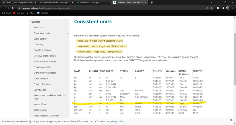
- We go with given dimensions as in the question ( gm-mm-ms )
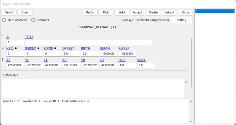
- Planer Rigidwall is made and is move the tail to -20mm apart from shell
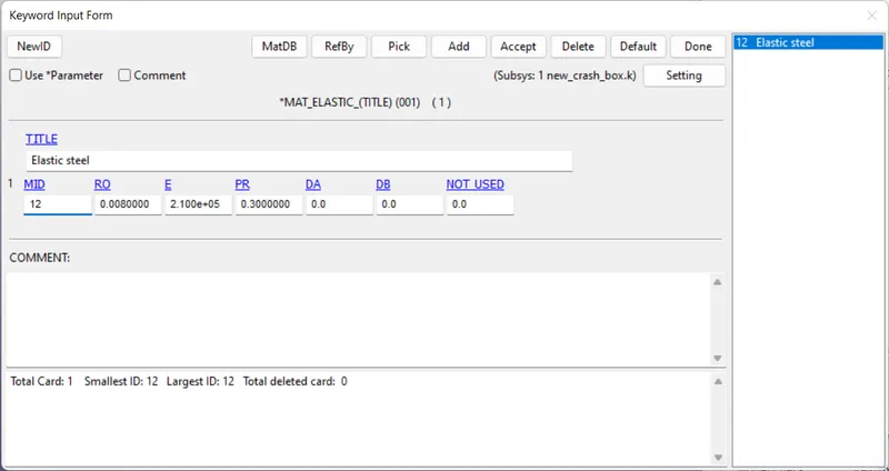
- Apply the elastic material in MAT
- Material for spotweld
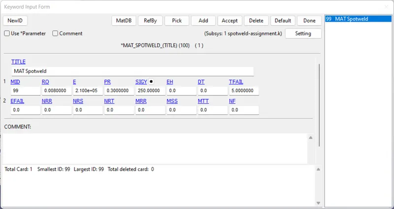
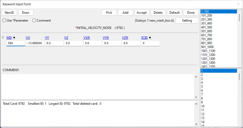
- Provide velocity and keep it in given unit
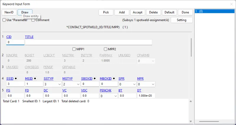
- Apply connection between spotweld & Plate
- Create cs for SLEOUT
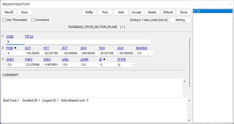
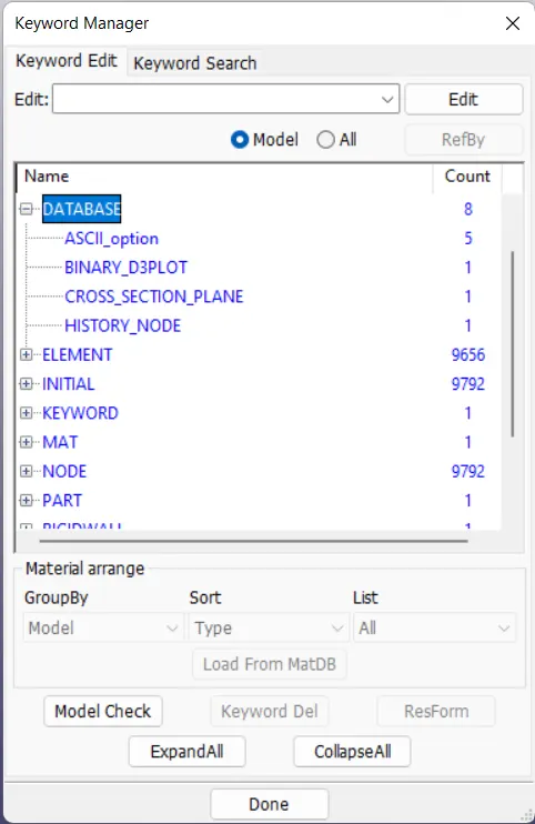
- Give the required outputs in DATABASE
- Go for LS-RUN.
Deliverables: