Week - 5 - Modelling Spotwelds
AIM:The main aim of this week challenge is to model spotwelds for the given model. The spotwelds should be modeled in two different ways
1. with beam elements
2. with solid elements
The result for the two methods are then analysed and the appropriate failure modes are then calibrated.
PROCEDURE:
Modelling of spotwelds using beam elements:
STEP 1: Open the LS-DYNA pre post and import the basic file containing the nodes and element as shown in Figure1. Figure2 shows the keywords used in the importd file.
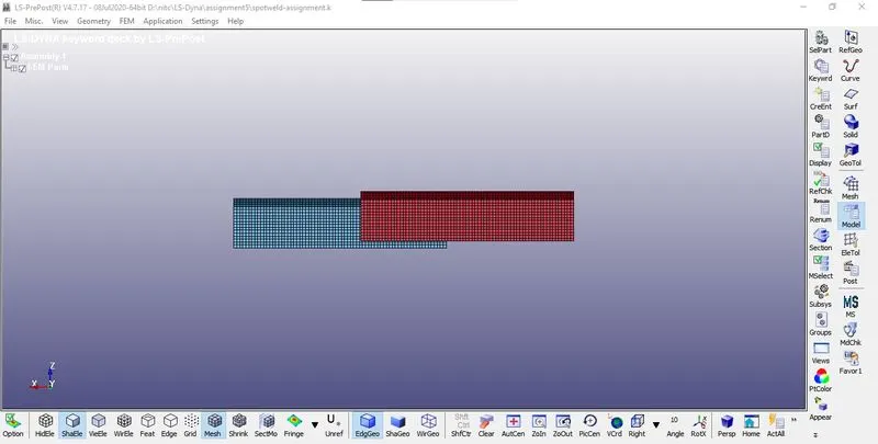 Figure1
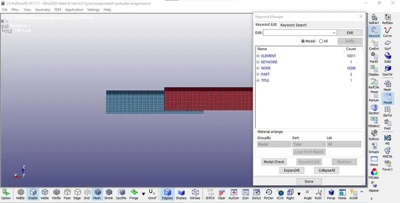 Figure2
STEP 2:Now create material and section cards for the parts.
STEP 3:Open the keyword manager and check the de button. Under the MAT keyword select the MAT 24
PIECEWISE LINEAR PLASTICITY as shown in Figure3
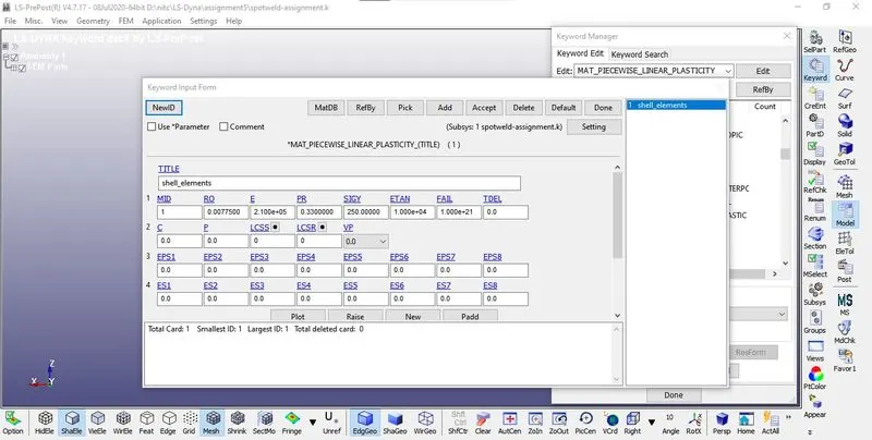 Figure3
STEP 4:Open the keyword manager and check the all button. Under the SECTION keyword select the SHELL card for the parts. Now give the properties of shell as desired as shown in Figure4
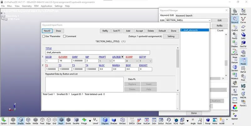 Figure4
STEP 5: Now go to PART keyword and assign the part with the desired material and section cards as shown in Figure5&6
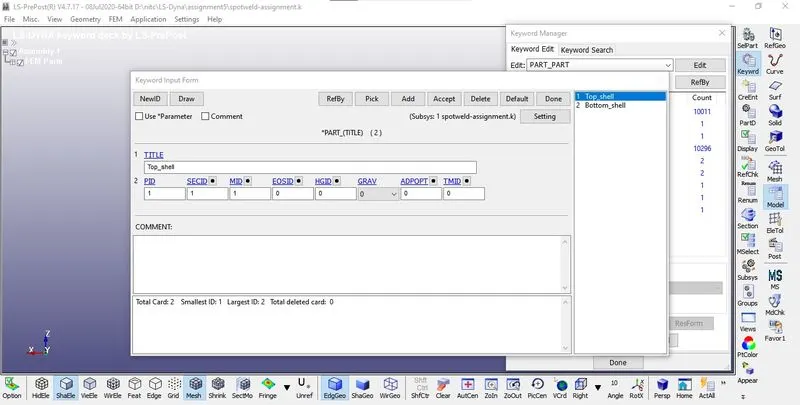 Figure5
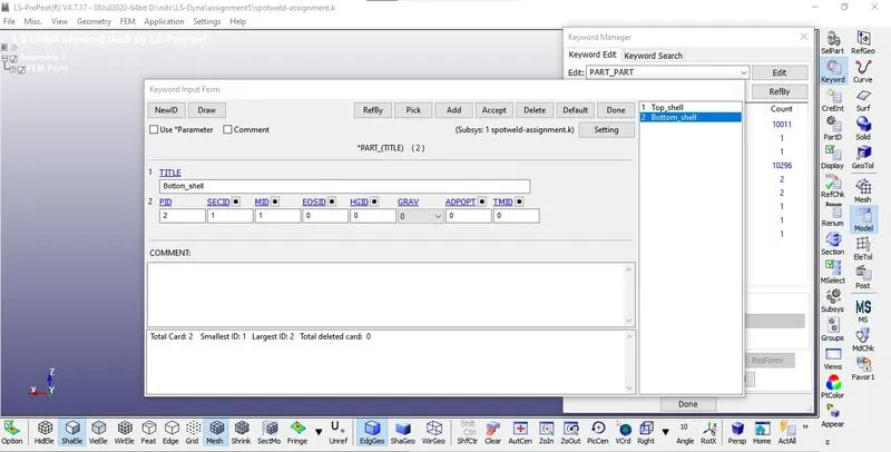 Figure6
STEP 6: Go to element generation and check the beam radio button and select the nodes between which you need to create beam elements. The position of the beam elements should be the similar to one asked in the question as shown in Figure7&8
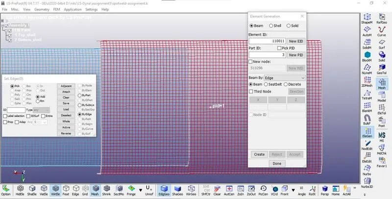 Figure7
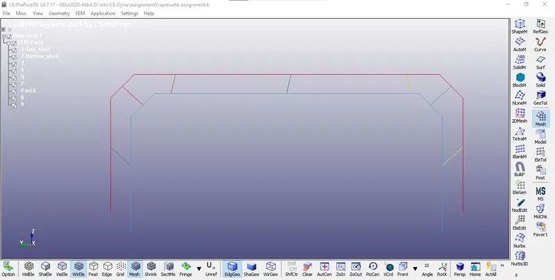 Figure8
STEP 7:Open the keyword manager and check the all button.Under the MAT keyword select the MAT 100 SPOTWELD as shown in Figure9
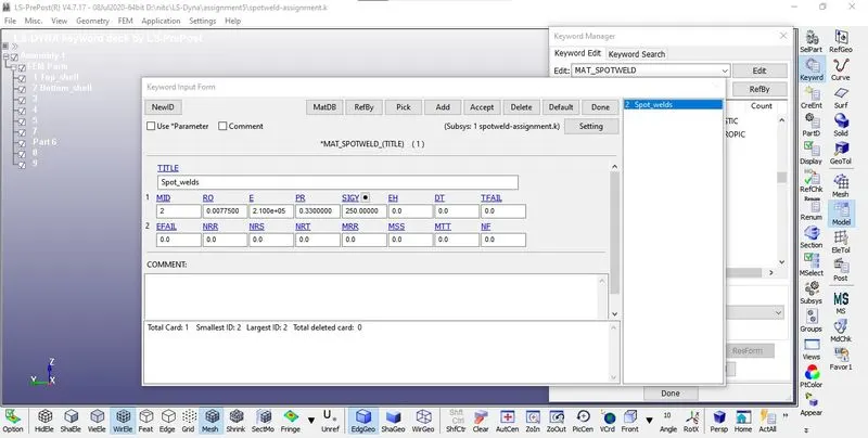 Figure9
STEP 8:Open the keyword manager and check the all button.Under the SECTION keyword select the BEAM card the spotwelds.Now give the properties of shell as desired as shown in Figure10
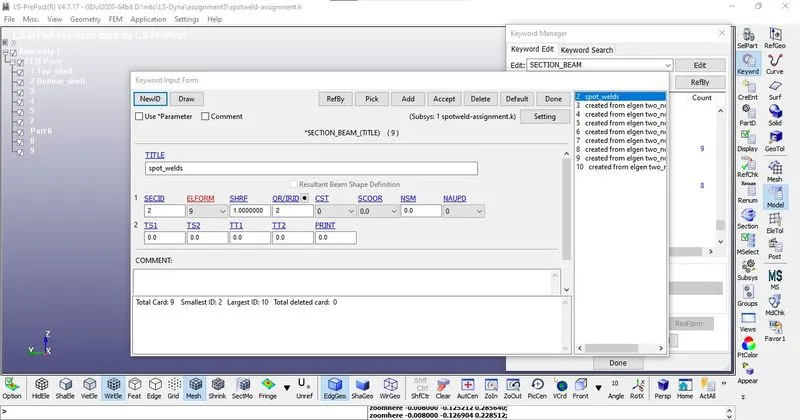 Figure10
STEP 9:Now go to PART keyword and assign the spotwelds with the desired material and section cards as shown in Figure11.
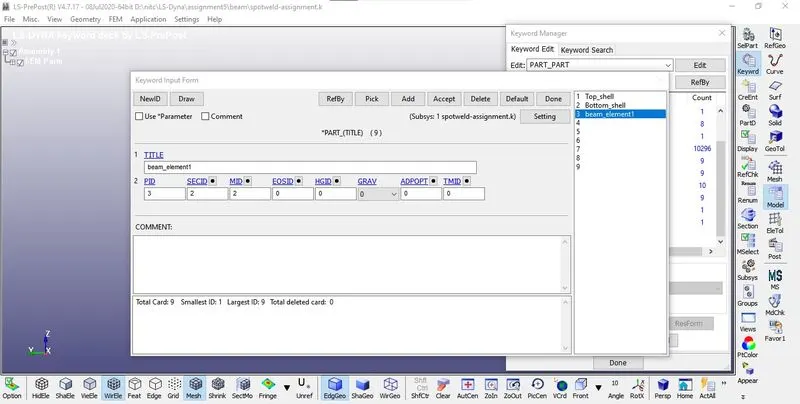 Figure11
STEP 10:Now go to the create entity tab and create a SPC constrained for set of nodes to be fixed in all direction as shown in Figure12
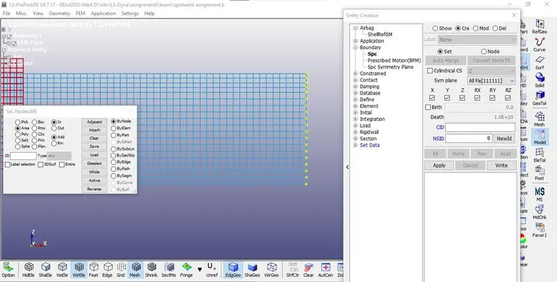 Figure12
STEP 11:Now define a curve in order to give the displacement boundary condition.
STEP 12:Open the keyword manager and check the all button.Under the DEFINE keyword select the CURVE as shown in Figure13
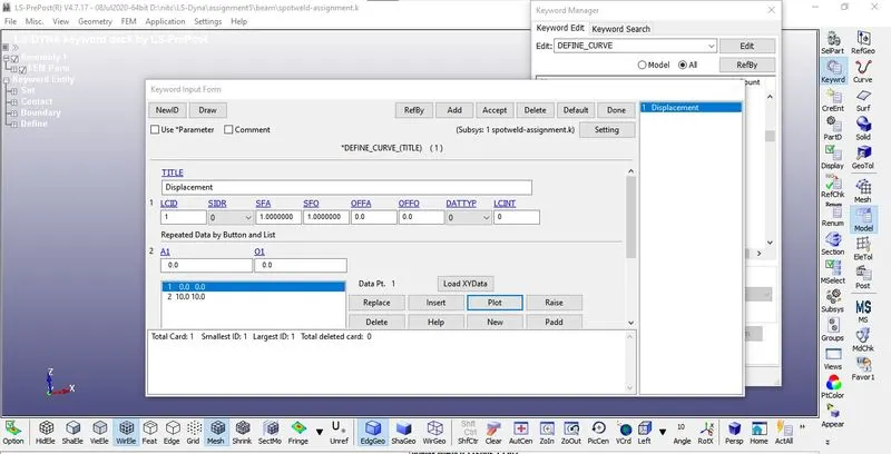 Figure13
STEP 13: Open the keyword manager and check the all button. Under the BOUNDARY keyword select the PRESCRIBED MOTION_SET as shown in Figure14
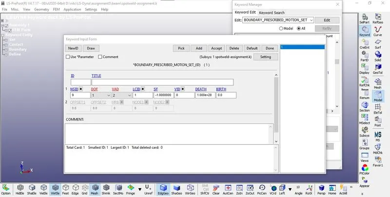 Figure14
STEP 14:To create a contact first create a part ID set and node set for the master set and node set. Open the keyword manager and check the all button.Under the CONTACT keyword and select AUTOMATIC SINGLE SURFACE as shown in Figure15
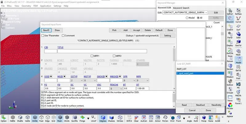 Figure15
Open the keyword manager and check the all button. Under the CONTACT keyword and select TIED SHELL EDGE TO SURFACE as shown in Figure16
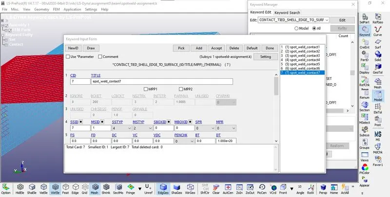 Figure15
STEP 15: Open the keyword manager and check the all button.Under the CONTROL keyword and select TERMINATION.Now give the total time of the simulation as shown in Figure16
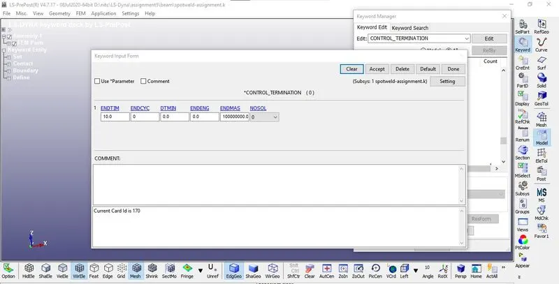 Figure16
STEP 16: Open the keyword manager and check the all button. Under the DATABASE keyword and select ASCII,D3PLC and CROSS_SECTION_SET as shown in Figure17 and 18.
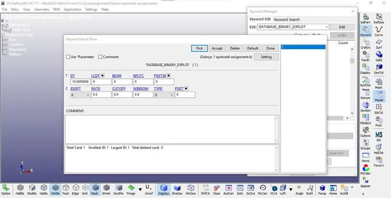 Figure17
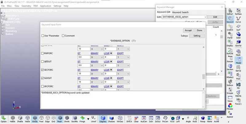 Figure18
In order to capture the exact failure modes the simulation is run at two different failure model.
The failure is made at time 5 sec and 8.5 sec and the shear force, axial force and resultant moment are tab
TIME AXIAL FORCE SHEAR FORCE
5 908 894
8.5 1210 965
Thus the failure method has been changed in the spotweld material as shown in Figure19
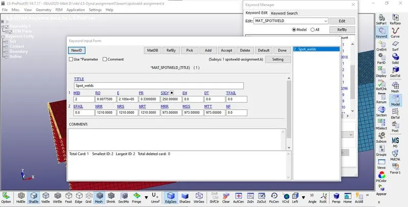 Figure19
Modelling of spotweld using solid elements:
STEP 17: Now create solid elements to replace the beam elements and give the appropriate section cards for it as shown in Figure20
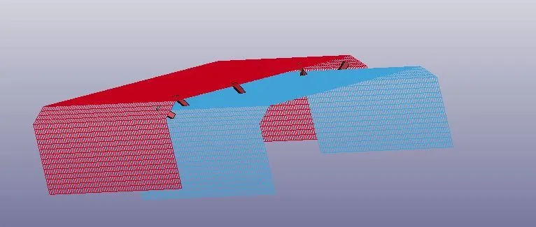 Figure20
In order to capture the exact failure modes the simulation is run at two different failure model as shown in Figure21
The failure is made at time 5 sec and 8.5 sec and the shear force, axial force and resultant moment are tabulated
TIME AXIAL FORCE SHEAR FORCE RESULTANT MOMENT
5 780 1800 11000
8.5 821 1800 11000
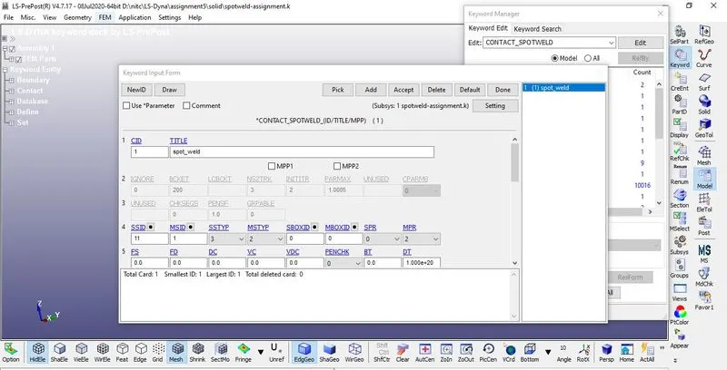 Figure21
RESULTS:
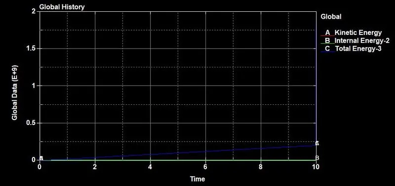
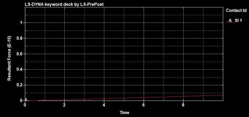
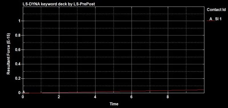
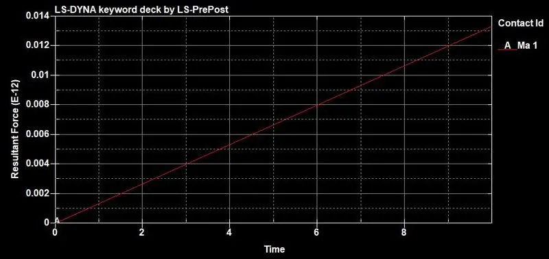
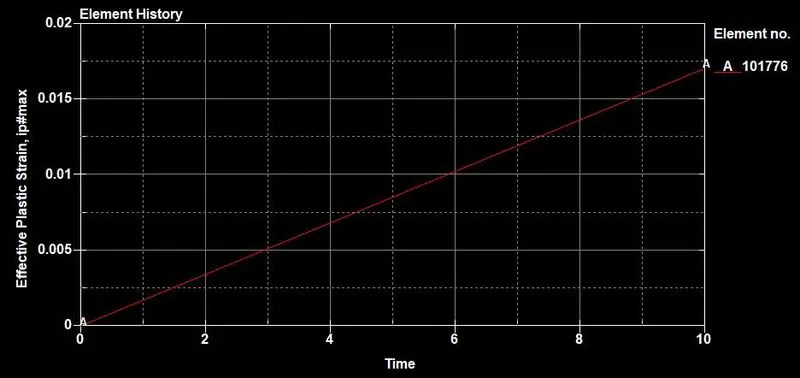
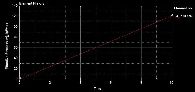
results of beam spotwelds
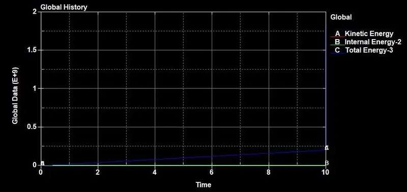
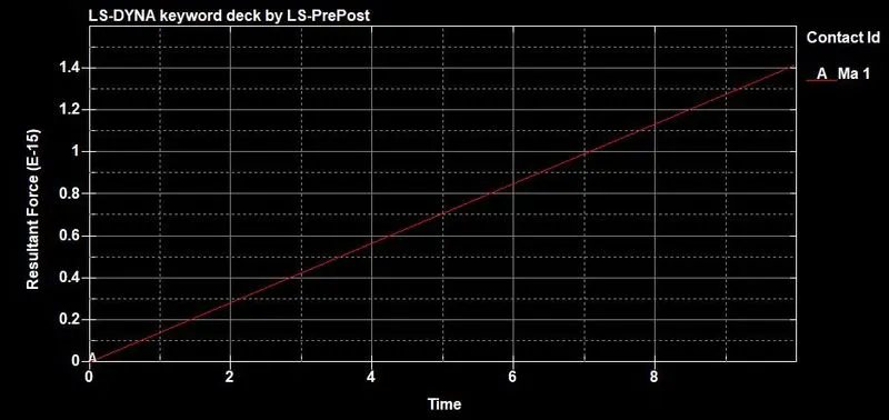
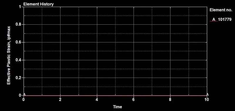
results of solid spotwelds