Week - 5 - Modelling Spotwelds
AIM:
To model spot welds for the given assembly and simulate crash analysis for the given model.
case1:Beam_spot_weld.
case2:Solid_spot_weld.
OBJECTIVE:
- To define splot welds using beam and solid elements.
- To crate a solver deck to perform crash analysis.
- To enter the values in g mm ms unit system.
- To assign the steel material properties for the crash box.
- Rigidwall should be create at some distance.
- To assign initial velocity of the crash box at 13.8mm/ms
- To create contact card.
- to create control keywords.
- To measure the cross-sectional force generated at the spot weld.
- To plot the total energy,kinetic energy,internal energy,hourglass energy in the graph.
- To compare the results with beam and solid elements.
MATERIAL PROPERTIES:
- crash box
Density=0.0078g/mm^3
young's modulus(E)=210000g/mm*ms2
possions ratio=0.3
yield strength=350g/mm*ms2
INTRODUCTION:
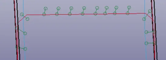
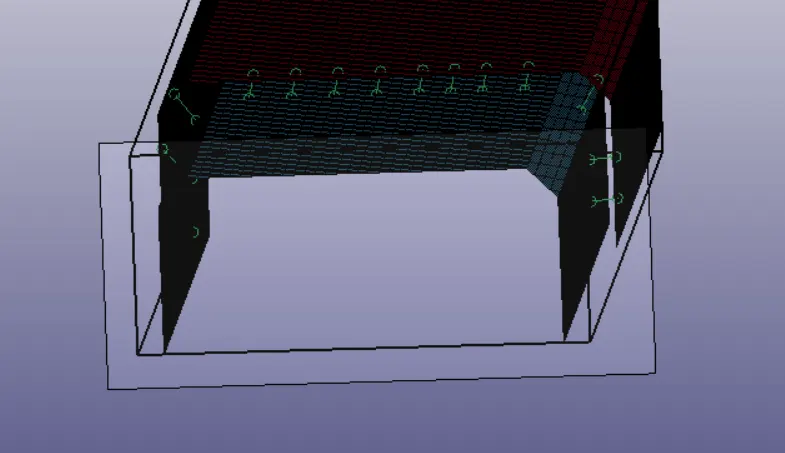
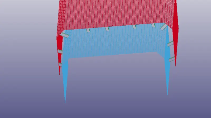
- The beam elements and solid elements are represented as spot welds between two thin sheets.In this simulation we come to known how to diploy spot welds in connection to two different sheets,which leads to sucessfull application of welid failure while running the simulation.
1.Beam elements.
2.Solid elements.
PROCEDURE:
- SIMULATION USING BEAM ELEMENTS.
1.Importing:
FILE>OPEN>LS-DYNA KEYWORD FILE>SPOTWELD_ASSIGNMENT.
Then go to to MODEL AND PART COMMAND>KEYWORD MANAGER.we can check the keywords in the model.
2.creating beam spot welds:
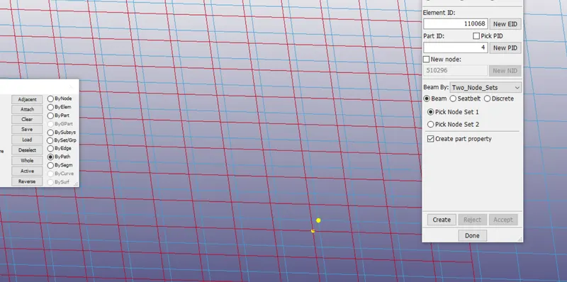
- Go to mesh>Element Generation>Beam>By Two_node_sets>select the 1st node>select the 2nd node>create>done.
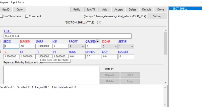
3.Defining section card for the shell and beam element:
- The thickness of the crash box is defined as 1.5mm.
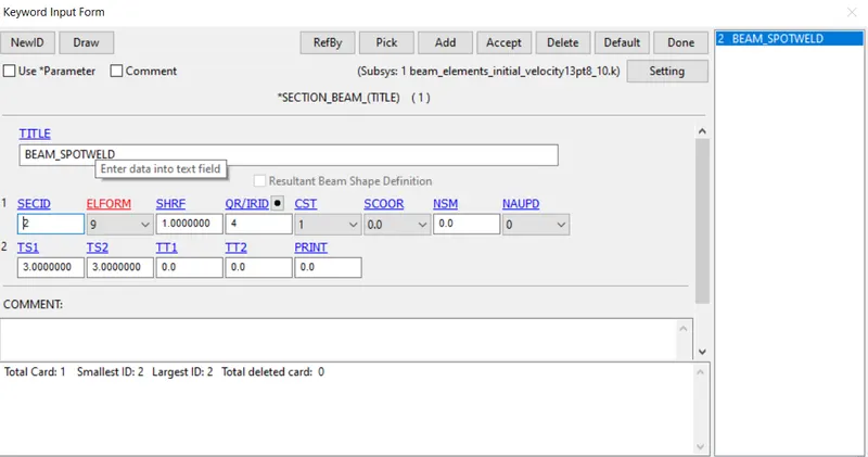
- Go to model and part command>keyword manager>all>section>beam>title=BEAM_SPOTWELD>SECID=2>ELEMFORM=9>QR/IRID=4>T1=3>ACCEPT DONE.
4.Defining material card for the shell and beam element:
- shell Element:
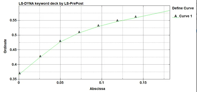
plastic behaviour using the MAT_24 card.first define the curve between effective plastic strain and effective stress.
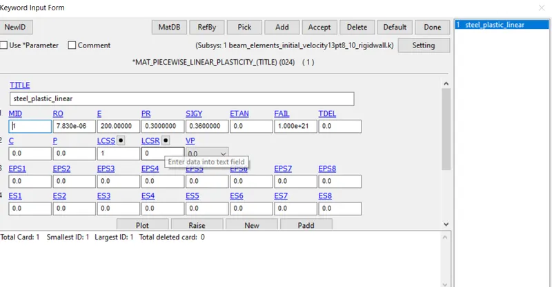
link the curve to the MAT_24 material card by using steel material by giving the material properties of the corresponding material and load curve using LCSS
- Beam Elements:
These two shell parts should be connected with spot welds by using beam elemnts.After several failure models have been developed in widely using LS-DYNA software to predicit spot weld failure during crash simulation.MAT_SPOTWELD_(TITLE)(100) is found and for spotweld the id should be started with 100 because industries will have some codes to start with ID beacuse it include 'N' number of sub-systems in it.so that we can check with the particular ID.
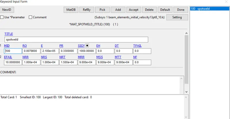
The Nrr,Mrs,Nrs and Nrt values are maximum spot weld force and moments prior to failure,which are generated from the experimental tests and performed on different loading cases,such as tension-shear(TS),coach-peel(CP).
5.Defing the section card and material card to the part:
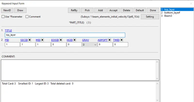
GO TO MODEL AND PART COMMAND>PART DATA.We can see that the model consist of two parts rename it as top and bottom part and assigining the particular property card.
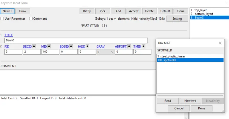
The spot weld beam elements also consist of material card and section card to be assigned.
6.define rigidwall:
The rigidwall should be created at some distance for the crash box to travel and hit the rigidwall.The rigidwall is super stiffer so the rigidwall will be the master part and the remaining crash box travelling towards the rigidwall will be the slave part.
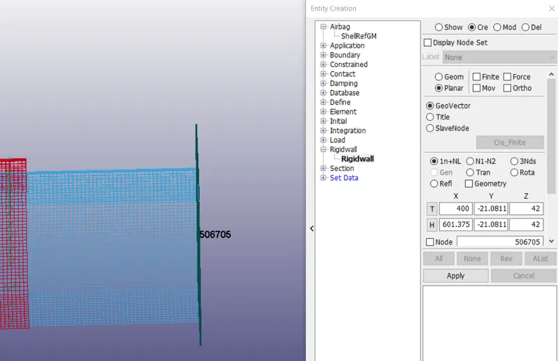
After creating the rigidwall the rigidwal should be translated to some distance to move with some initial velocity.
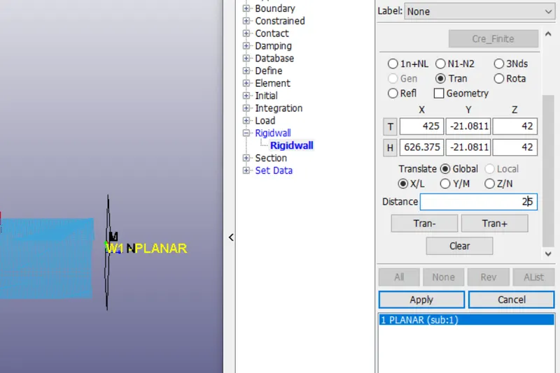
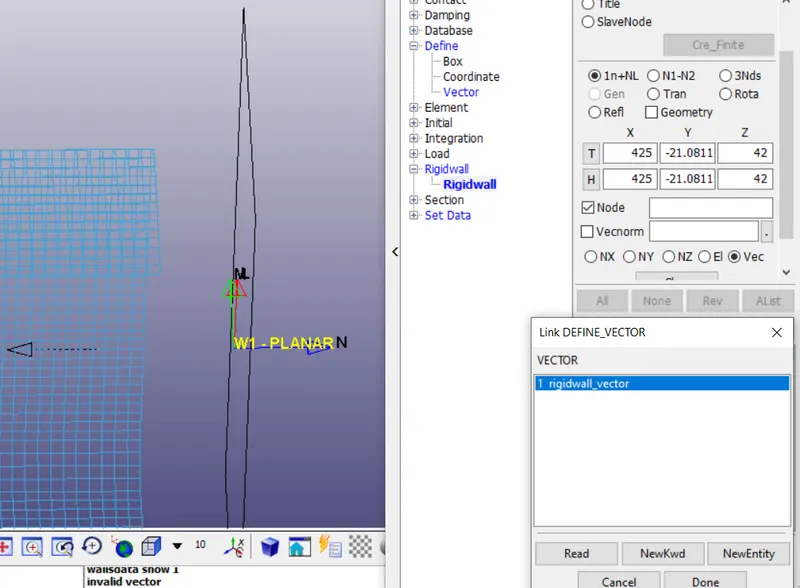
The rigidwall vector direction should be towards the crash box.then only it will consider as contact.so we should provide a vector direction and change the direction of the rigidwall.
The rigidwall is created along the vector direction.
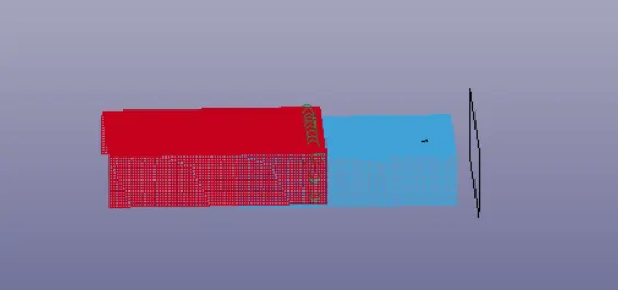
6.Define initial velocity:
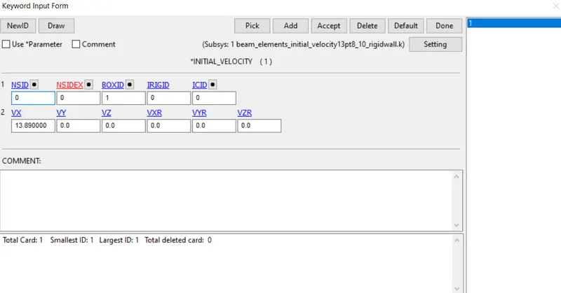
The initial velocity of the crash box is 13.89mm/ms is provided using BOXID.we can define a box for the entire crash box and provide initial velocity.
7.Define contact:
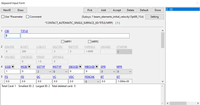
Here,in this model we have two different types of contact is defined:
1.AUTOMATIC_SINGLE_SURFACE.
This surface is connected with the single surface and the slave part is defined.
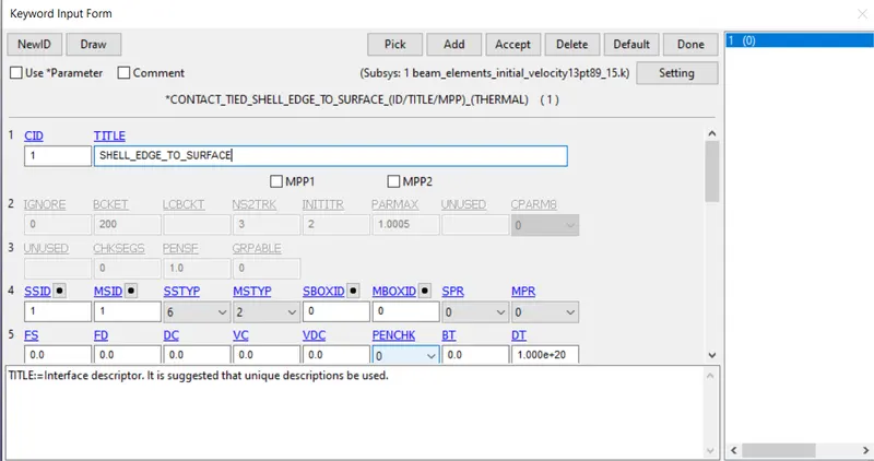
2.TIED_EDGE_SHELL_TO_SURFACE
The surface should have connected with the surface with the spotweld nodes as slave and master nodes as part nodes.it can be defined by setpart.
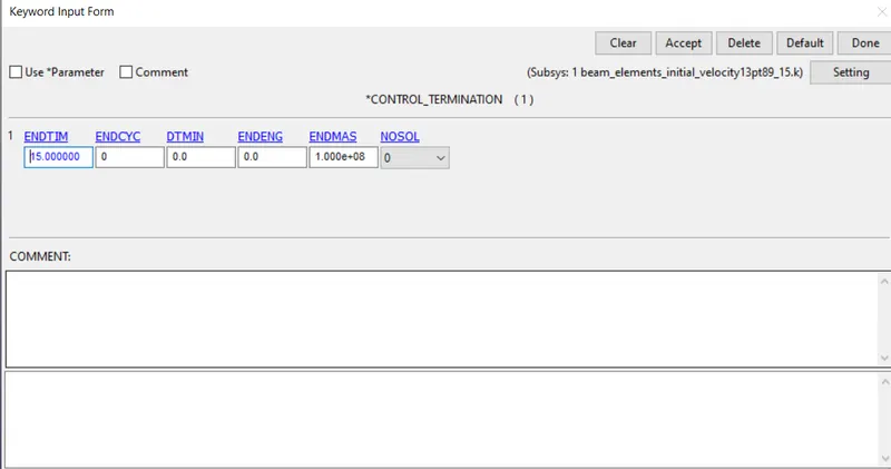
8.Control termination:
The termination time to run and model is given here it will make the body to move and hit the rigidwall and rebound back with some velocity with in the termination time provided.
9.Datbase for output:
In database we request for ASSIC:glstat,matsum,rcforce,swforce,elout,ndout and D3PLOT.

- SIMULATION USING SOLID SPOT WELD ELEMENTS:
For solid spot weld simulation the step of simulation is same but in place of beam elements we should change the solid elements in section id and assign them to the part and run the simulation.
1.open the BEAM_SPOTWELD.K File and delete the beam elements.
2. Go to element tools module>element edit>create>Hexa set part for all the solid elements and select the 8 nodes in clock-wise direction so that the solid elements are generated by selecting the 8 nodes.
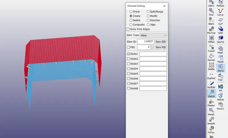
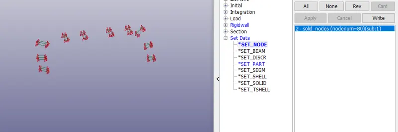
3.A node set for the solid element should be created for 1 solid element it consist of 8 nodes we should assign node set for the entire solid elements.
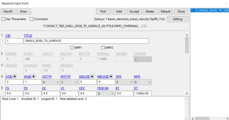
4.now,define the contact for the solid spotweld nodes and part using CONTACT_TIED_SHEEL_EDGE_T0_SURFACE .and the master as the part and slave as the solid nodes.
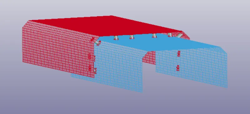
5.Every thing is set to run the simulation with solid spotwelds.
Results:
- BEAM SPOT WELD
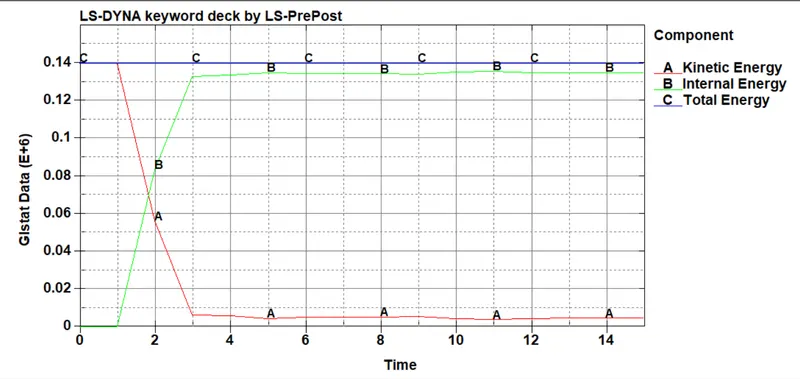
- Forces generated at the spotweld area.
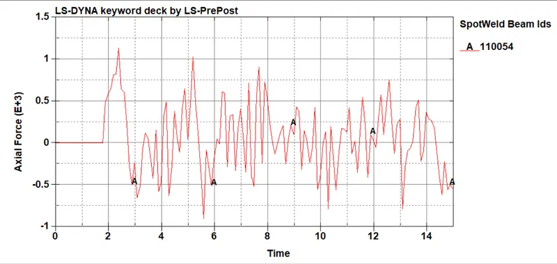
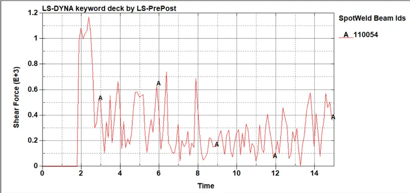
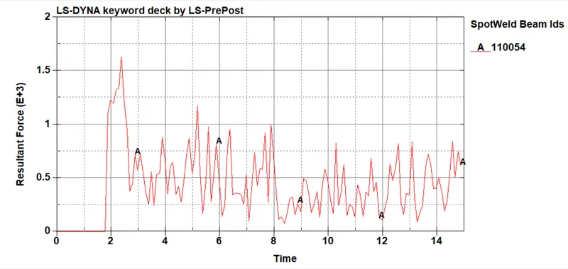
The animation of the beam spotweld is shown in below link
- SOLID SPOTWELD:
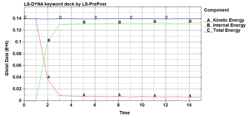
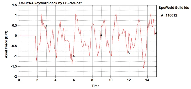
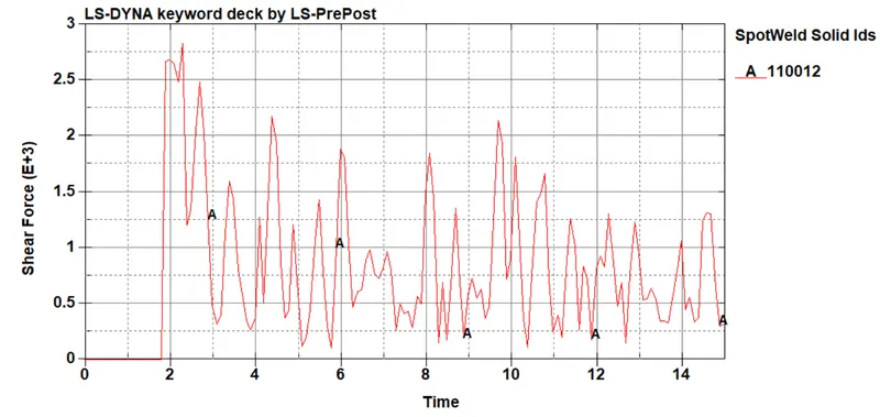
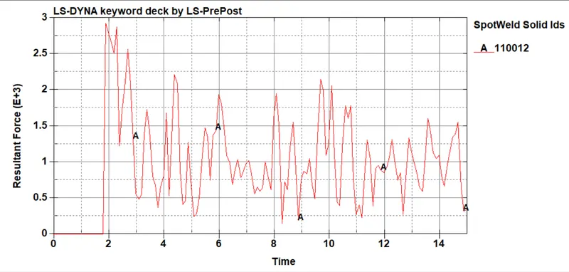
The animation of the solid spotweld is shown in below link:
Result:
The spotweld using solid elements and beam elements is done and the forces obtained are shown above.
LEARNING OUTCOMES:
- To import the keyword file.
- To assign the mat and section cards to the part.
- To create beam and solid elements.
- To define rigidwall.
- To define initial velocity.
- To plot output results.