WEEK 5 - MODELLING SPOTWELDS
AIM:
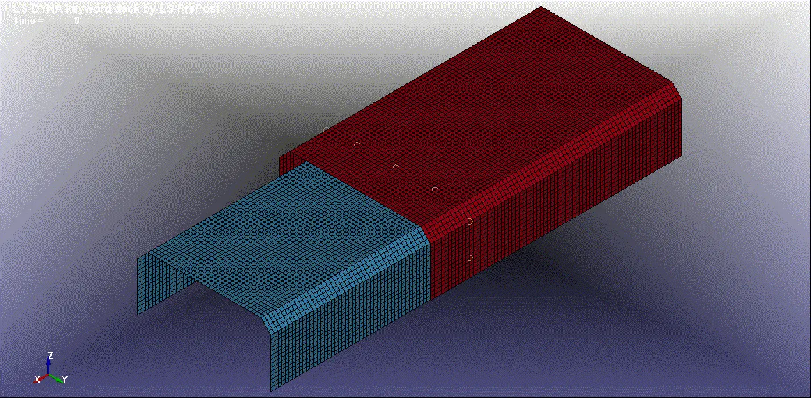
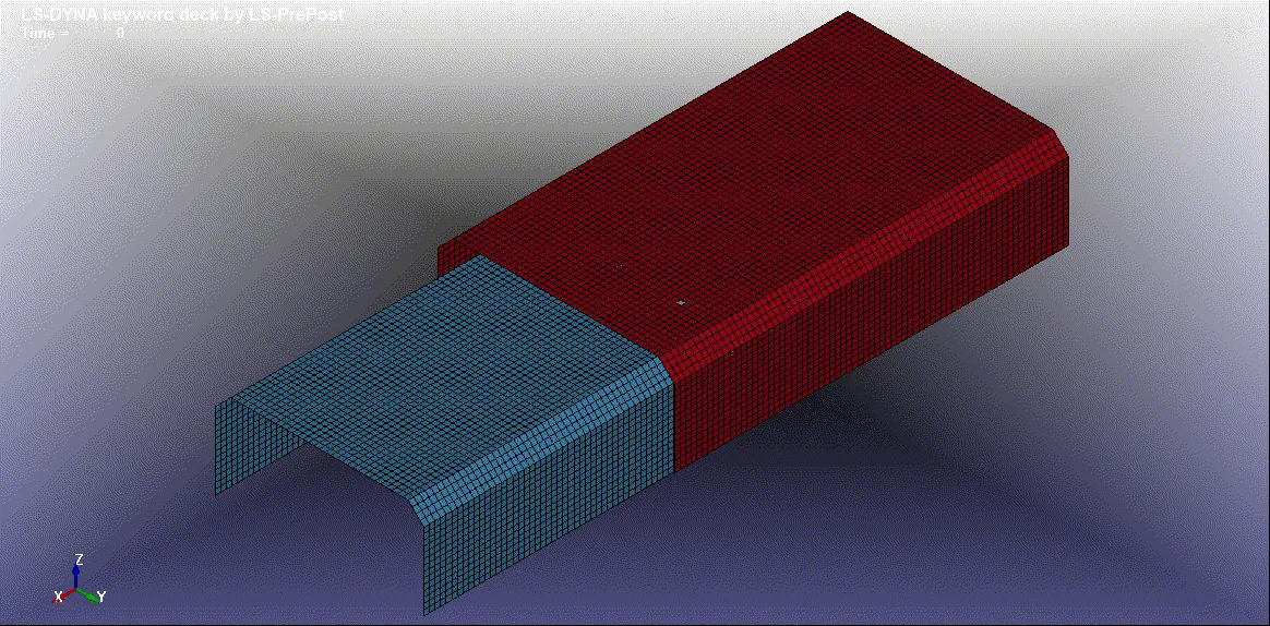
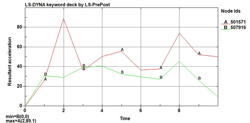
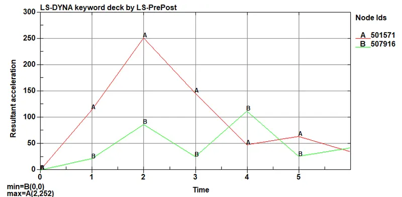
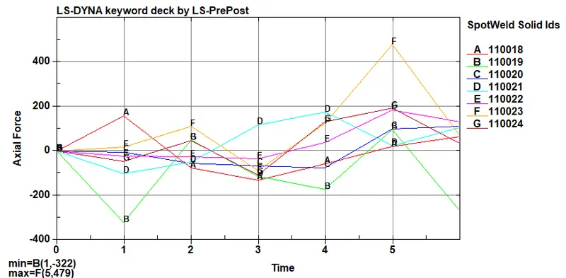
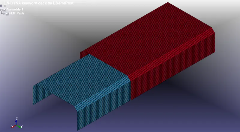
To Run a crash box simulation using beam spotweld and solid hexa spotweld. Comparing axial and Accleration among beam and solid elements.
GIVEN:
METHODOLOGY:
- Methods has been followed same as assignment 4 except creating spotweld and boundary conditions.
- There are four types spotweld creation here we are using two types and comparing them with the results
PROCEDURE:
CASE-1: BEAM SPOTWELD
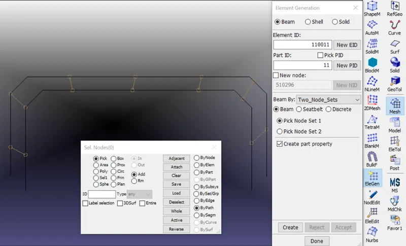
Creating spotweld between the two shell part by using beam element that is connected at both ends to the nodes of both shell elements.
Go to Mesh_EleGen and select the two node set to create a beam element like the below image
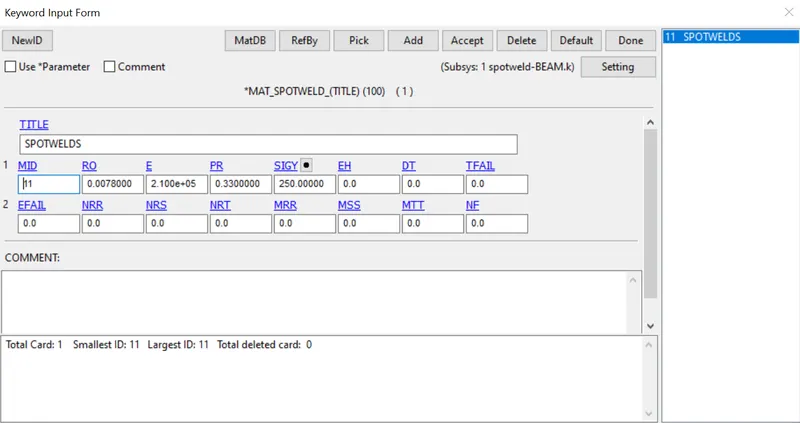
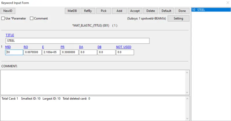
Creating material for the Spotweld and the two shell part
MAT_SPOTWELD
MAT_ELASTIC
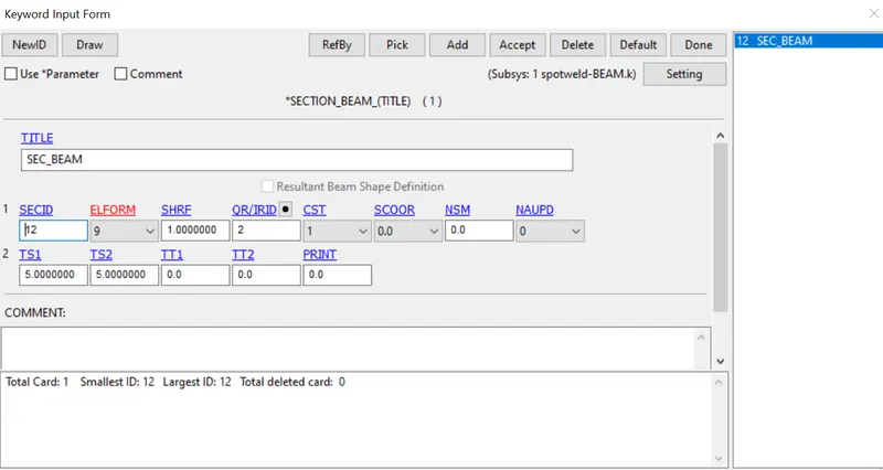
Beam Section has been created for Spotweld and Shell Section for the two part
SECTION_BEAM
SECTION_SHELL
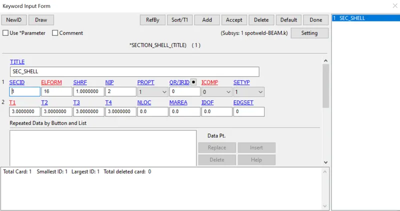
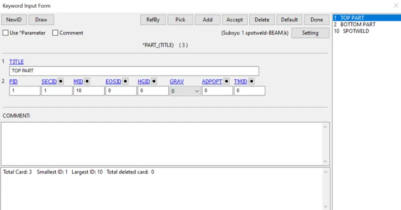
Assigning the Section and material to the Two shell part and Spotweld.
SPOTWELD
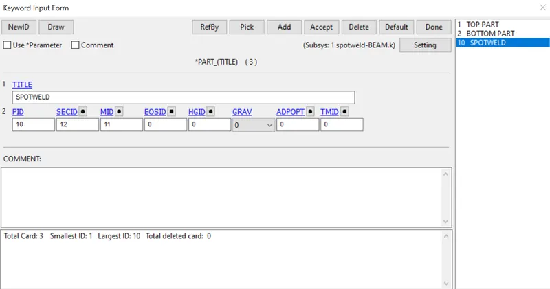
TOP AND BOTTOM SHELL PART
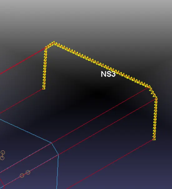
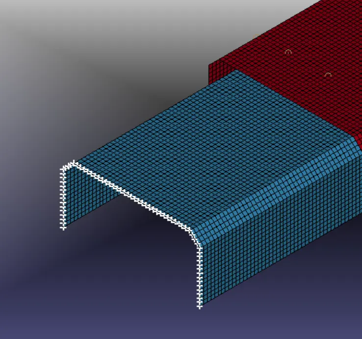
Then go to create Entity_Set data_Create node set for the Boundary conditions applied on both end
BOUNDARY_PRESCRIBED_MOTION_SET
Displacement has been applied on the node set and assign that node set to this Boundary conditions
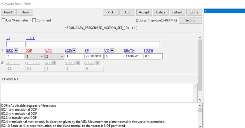
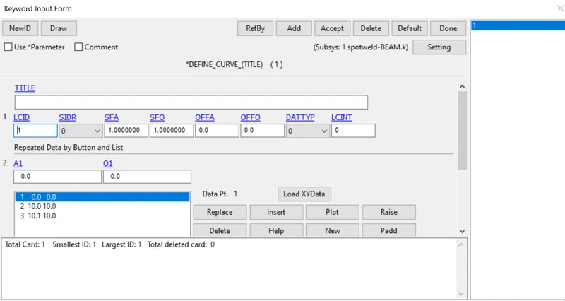
LOAD CURVE
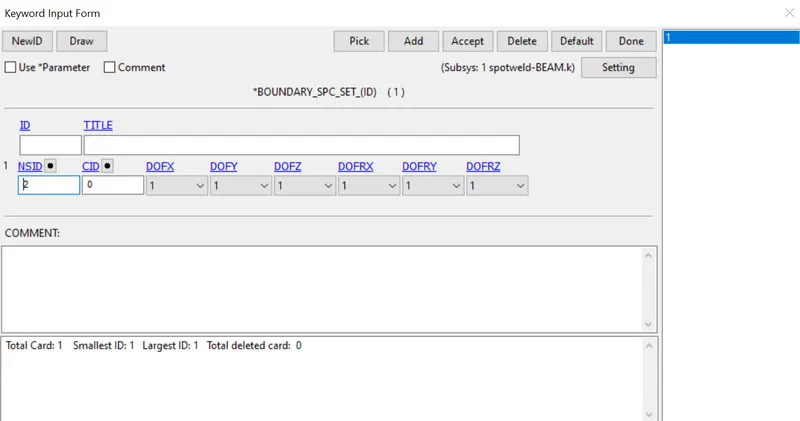
BOUNDARY_SPC_SET
CONTACT:
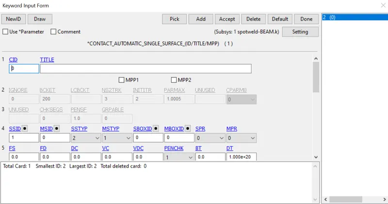
Create a contact interface using the option Automatic_Single_Surface, select the crash box node set as a slave set nodes
CONTACT_AUTOMATIC_SINGLE_SURFACE
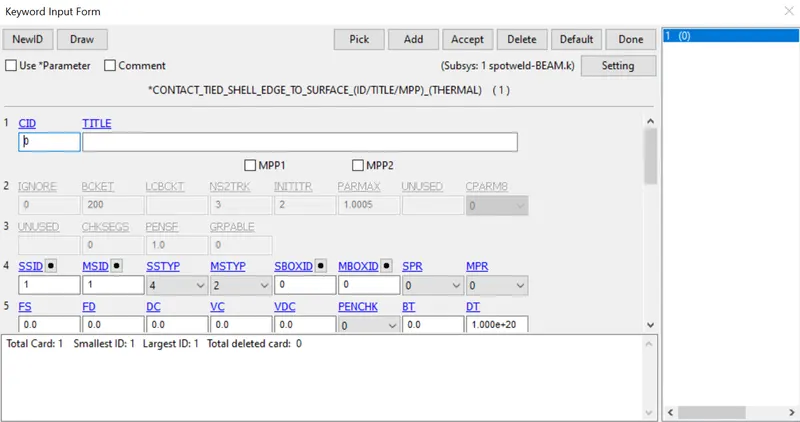
CONTACT_TIED_SHELL_EDGE_TO_SURFACE
CONTROL:
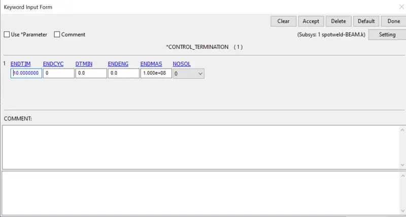
TERMINATION:
Define a termination card with a run time of 10 ms
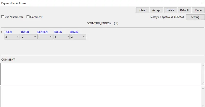
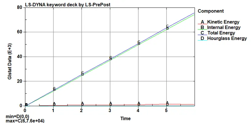
CONTROL_ENERGY
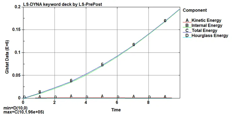
Energy card has to be created for getting Internal and kinetic energy in Glstat output
DATABASE:
All output parameters requested are defined using this card
ASCII:
Choose=>GLSTAT,SWFORC,NODOUT and enter dt value as 1 to define a necessary output files.
D3PLOT:
Binary file as D3plot is a Database for complete output states
DT as 1
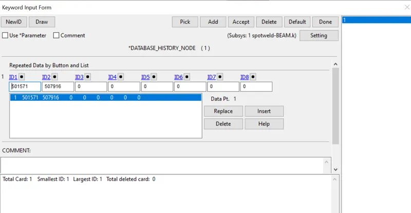
HISTORY NODE:
This set node containing required nodes for which the nodal output parameters that need to be resulted
Check the model by going to Model Checking in application save the model in .k file and run the simulation
CASE 2: SOLID SPOTWELD
The above parameters are applied as same to the solid spotweld except with the few changes in Section and element Keywords.
SPOTWELD ELEMENT GENERATION:
To create a solid element EleTol_EleEdit_Create_Hexa
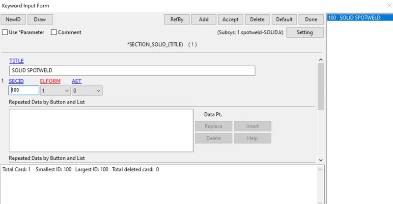
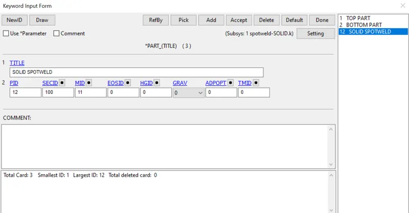
Section and Material for Solid spotweld has been assigned to the Part
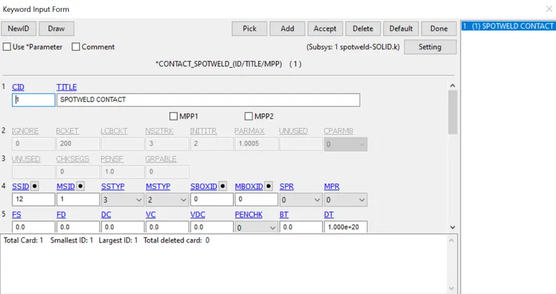
CONTACT_SPOTWELD
Check the model by going to Model Checking in application save the model in .k file and run the simulation
OUTPUT:
ANIMATION OF BOTH THE RESULT
BEAM SPOTWELD:
SOLID SPOTWELD:
COMPARING BOTH THE CASES:
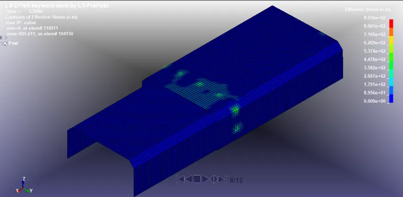
1. Vonmises stress For Spotweld_Beam:
Max stress - 895Mpa
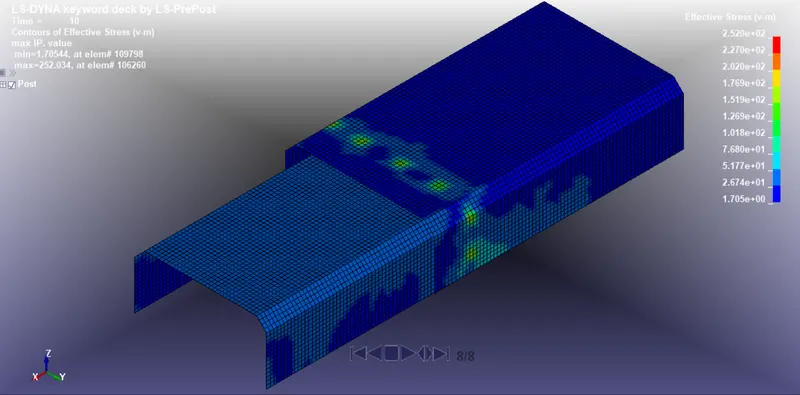
1. Vonmises stress For Spotweld_Solid:
Max stress - 252Mpa
2. Energy Graph:
3. Acceleration Graph:
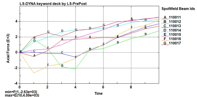
4. Axial Force For Spotweld:
CONCLUSION:
The Spotwelds are modelled using Beam and Solid Elements for the same component and Respective Section and Material has been assigned. While Beam element and Solid element resulted Graph and Stress, Solid Element has a better result as it adds stiffness to the component.Axial force acts low in the solid element when compared to beam.Thus the plot results are compared.