Modelling Spotwelds in LS-Dyna
Objective: To model spotweld using beam and solid elements and perform a crash simulation in LS-Dyna.
Procedure:
- Open the provided keyword file in the LS-PrePost, which contains the mesh information of two rail components.
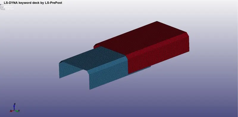
Fig 1: Meshed model.
- The initial keyword file contains only the element, node, and parts information available within it.
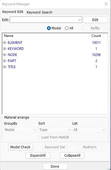
Fig 2: Initial keyword file information.
- To start with the deck preparation, we rename the auto-created parts with a suitable name and part ID to distinguish them and for further use.
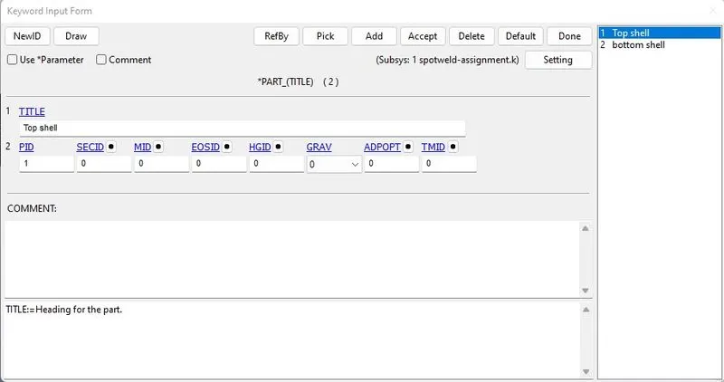
Fig 3: Rename the parts and IDs to differentiate them.
- Navigate to the element generation option from the mesh menu in the right ribbon to create a spot weld using the beam element.
- Choose the Two_Node_Sets option in the drop-down and select one node from each rail to create a beam element.
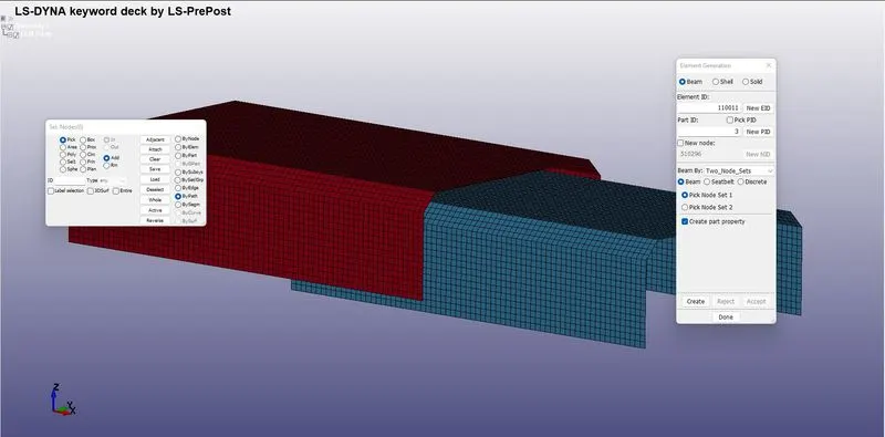
Fig 4: Beam element generation.
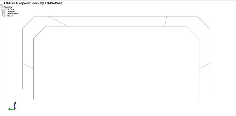
Fig 5: Four beam elements are created joining the two parts.
- A shell section keyword is included with a Fully integrated shell element (ELFORM=16) and assigned a thickness of 1.5mm.
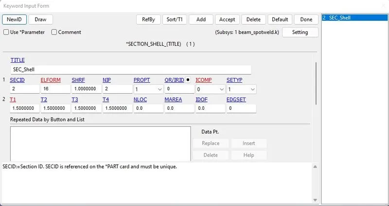
Fig 6: Shell section defined for the shell elements.
- A beam section keyword is included with spotweld beam (ELFORM=9) and assigned a thickness of 3mm with CST of 1.
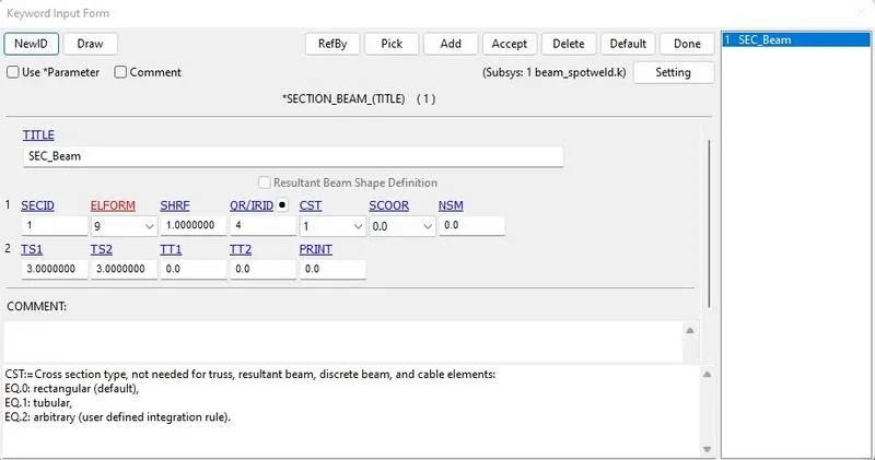
Fig 7: Beam section defined for the beam elements.
- MAT001-ELASTIC is defined with the following properties for the shell elements.
Density: 0.0078500 gm / mm3
Elastic Modulus: 210000 Mpa
Poisson’s Ratio: 0.33
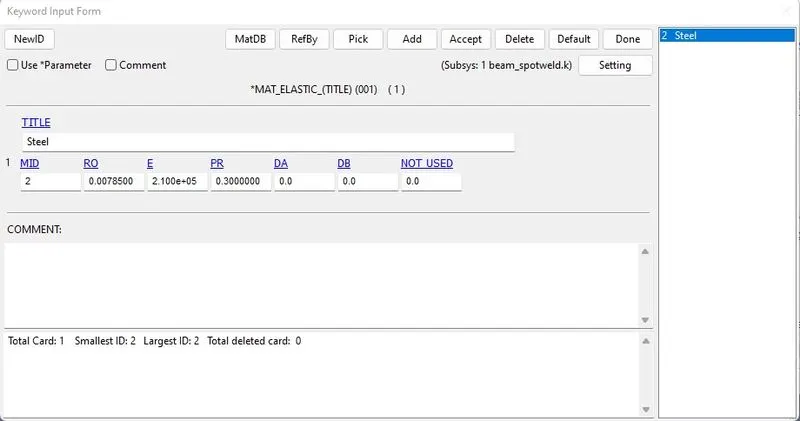
Fig 8: Material card is defined for the shell elements.
- MAT100-SPOTWELD is defined with the following properties for the beam elements.
Density: 0.0078500 gm / mm3
Elastic Modulus: 210000 Mpa
Poisson’s Ratio: 0.33
Tensile Yield Strength: 340 MPa
TFAIL: 6ms
EFAIL: 20
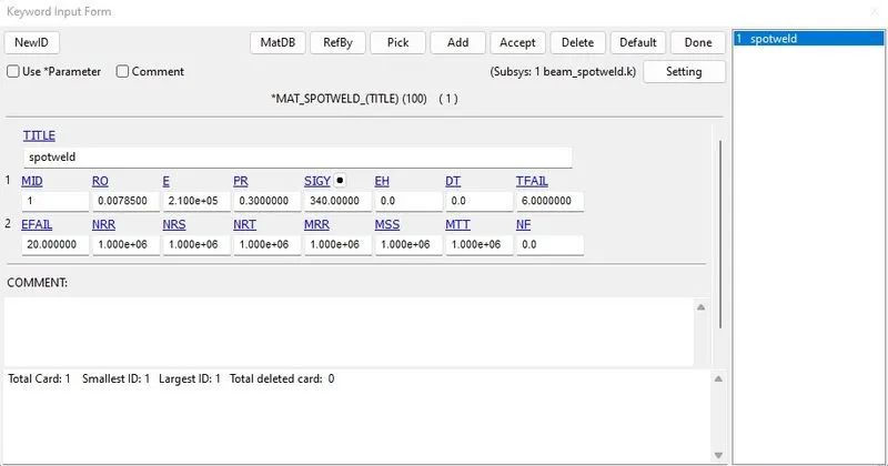
Fig 9: Material card is defined for the beam elements.
- Hourglass phenomena are expected in the shell elements; to avoid this hourglass effect, the hourglass keyword with Flanagan-Belytschko viscous form is added to take care of it.
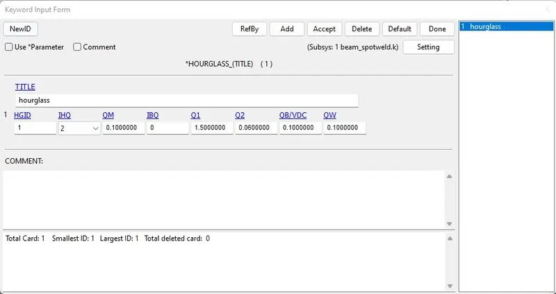
Fig 10: Hourglass card is defined for the shell elements.
- The material, hourglass form, and element formulation should be assigned to the part we have created earlier.
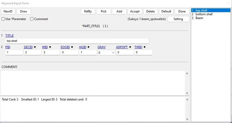
Fig 11: Material, section, and hourglass are assigned to the shell parts.
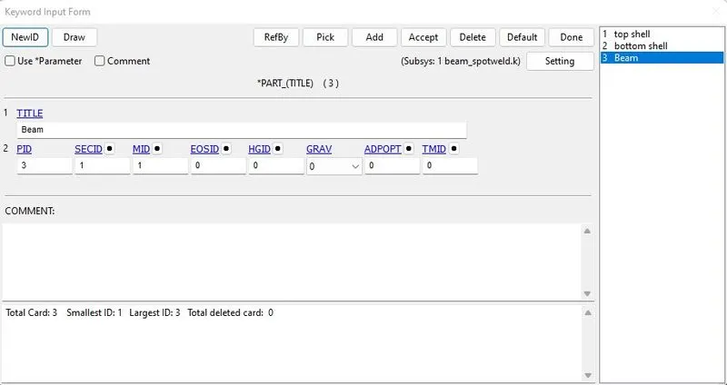
Fig 12: Material and section are assigned to the beam part.
- Navigate to the Set data options to create node sets and shell sets to define particular keywords using these sets.
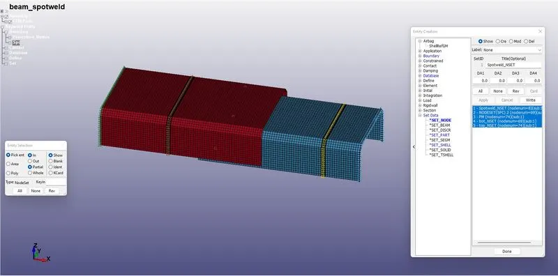
Fig 13: Few node sets are created to assign particular functions to them.
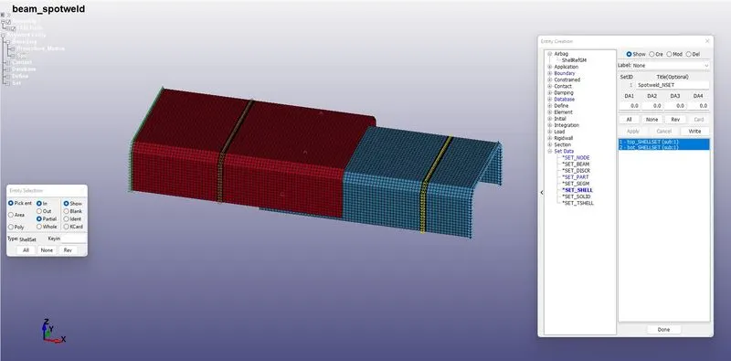
Fig 14: Few shell sets are created to assign particular functions to them.
- The bottom plate one end is completed fixed with SPC boundary condition and the top plate one end is given a prescribed motion with a displacement curve defined.
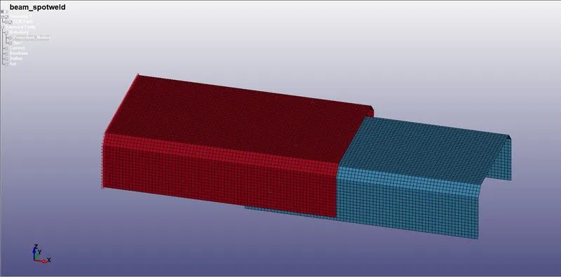
Fig 15: Node set representing the edge of the top plate.
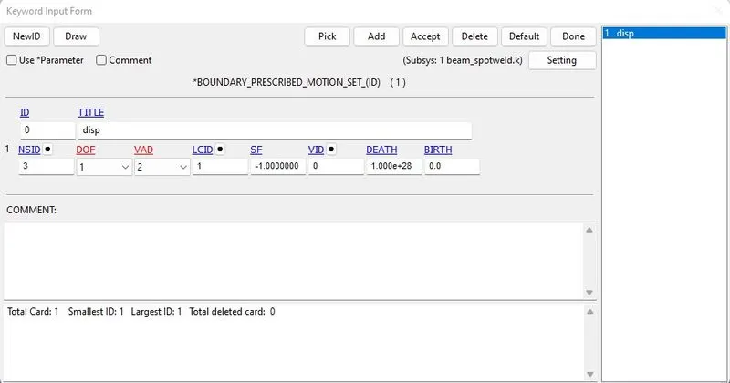
Fig 16: Displacement is defined for the top plate.
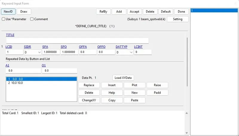
Fig 17: Curve data for the displacement is defined.
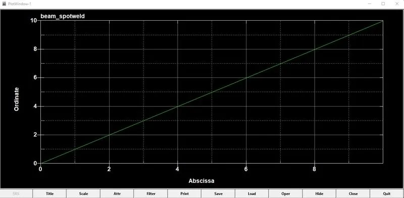
Fig 18: Displacement plot.
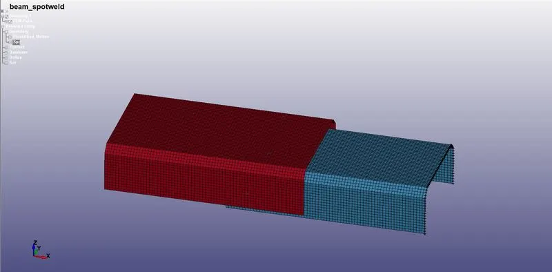
Fig 19: Node set representing the edge of the bottom plate.
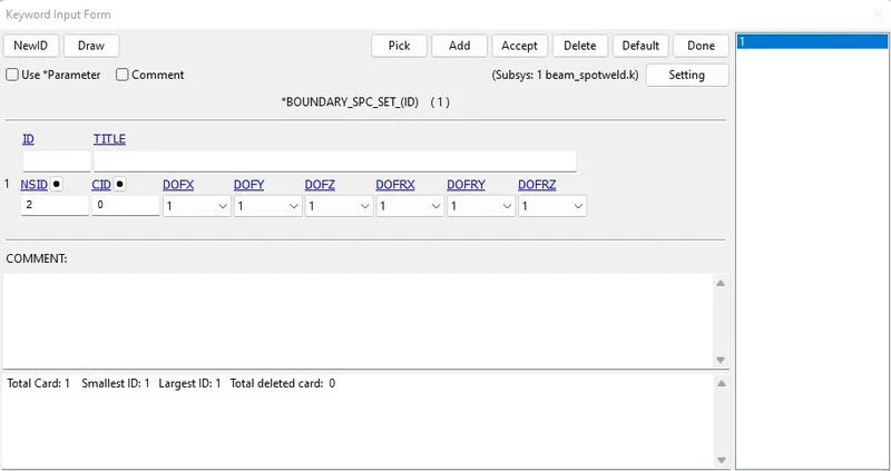
Fig 20: Bottom pate is constrained completely.
- For the shell elements, the AUTOMATIC_SINGLE_SURFACE contact card is defined.
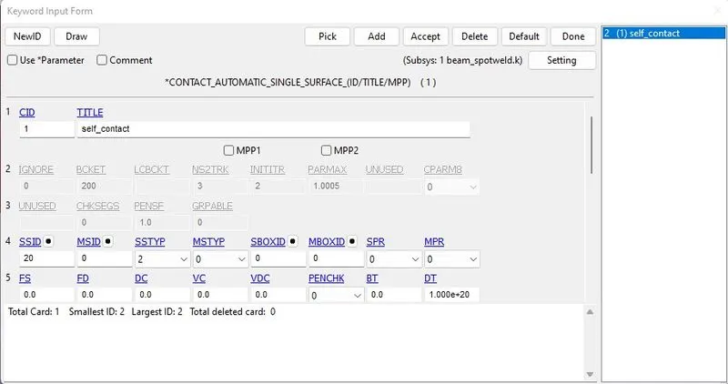
Fig 21: Self-contact card is defined for the shell elements.
- For the beam to shell elements, TIED_SHELL_EDGE_TO_SURFACE contact is defined.
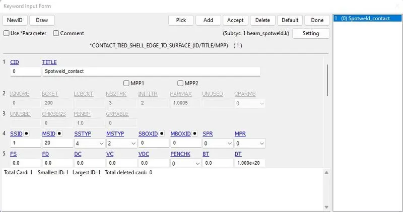
Fig 22: Contact is defined between the beam and the shell elements.
- The ASCII_option keyword from the DATABASE deck is used for the output requests, and GLSTAT, MATSUM, NODOUT, SECFORC, and SWFORCE options are checked.
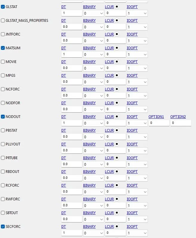
Fig 23: Output requests are defined.
- The BINARY_D3PLOT keyword from the DATABASE deck is used for the plots, and a DT of 1 is entered.
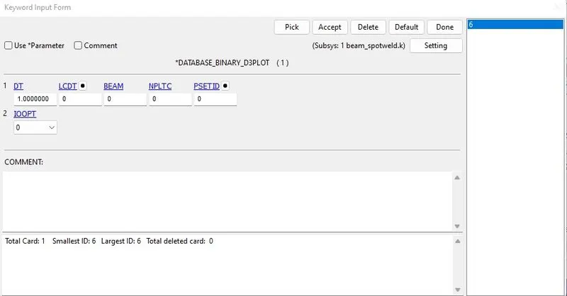
Fig 24: Plots at time intervals are defined.
- HISTORY_NODE keyword is used from the DATABASE deck to compute the variables of the nodes.
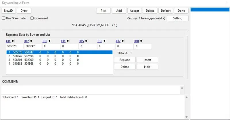
Fig 25: Node output is created to compute the variables.
- CROSS_SECTION_SET is defined to compute the sectional forces in the top and the bottom plate.
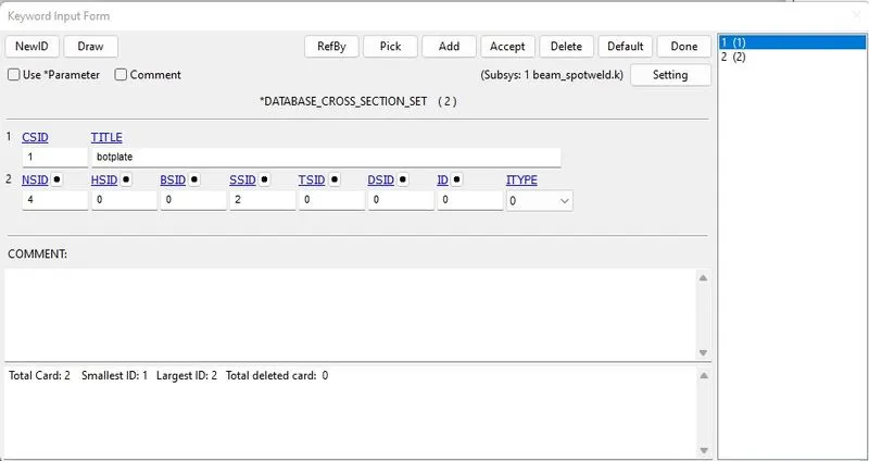
Fig 26: Cross-section card is defined to obtain data for the created section.
- Finally, the TERMINATION keyword from the CONTROL deck is used to define the end time of the simulation.
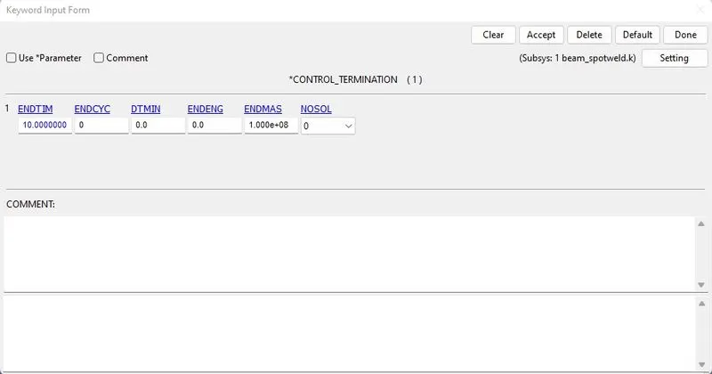
Fig 27: End time for the simulation is defined.
For Solid element creation:
- Navigate to the element generation option from the mesh menu in the right ribbon to create a spot weld using the solid element.
- Choose the Two_Shell_Sets option in the drop-down and select one shell element from each rail to create a solid element.
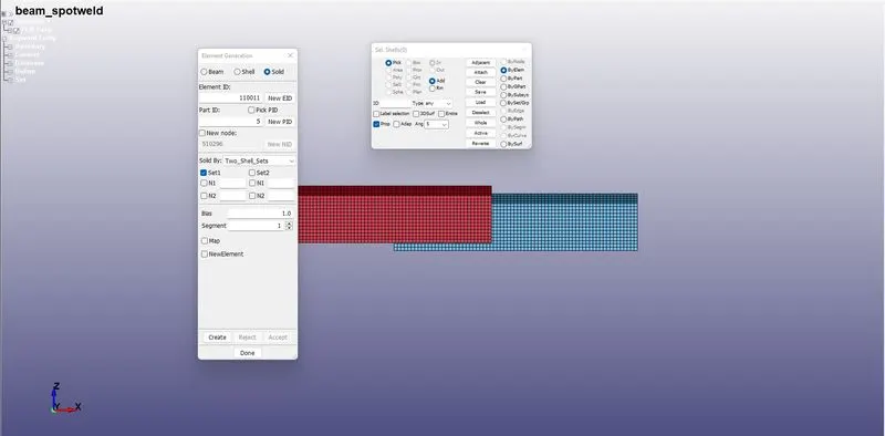
Fig 28: Options for creating the solid elements.
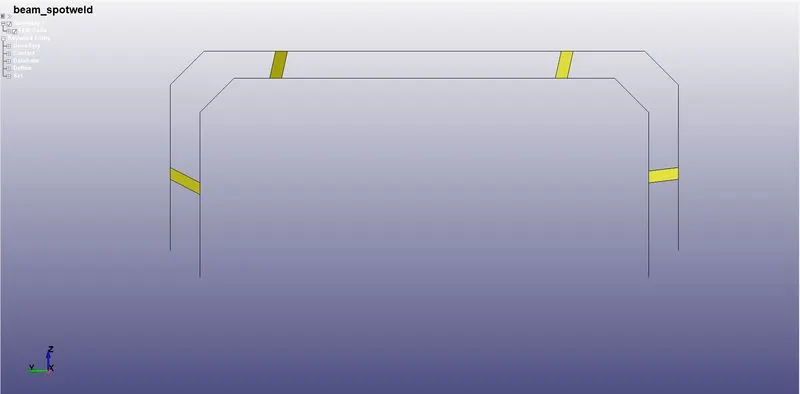
Fig 29: Solid elements represented in yellow color joins the two plates.
- A solid section keyword is included with a constant stress solid element (ELFORM=1).
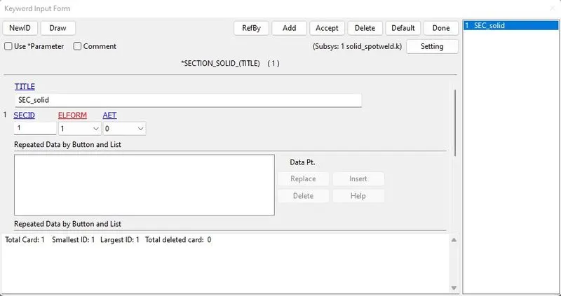
Fig 30: Solid section is defined for the solid elements.
- Rest all will remain the same.
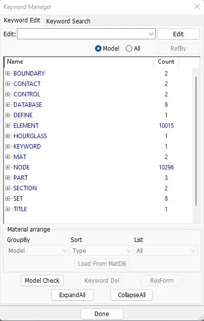
Fig 31: Fully defined deck.
Results:
- Open the Start LS-Dyna analysis, browse the keyword file, and hit run to run this keyword file.
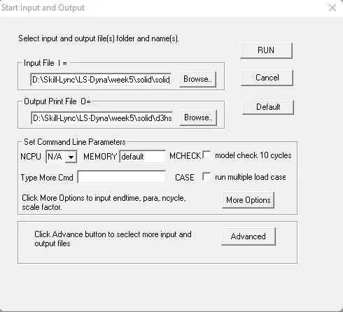
Fig 32: LS-Dyna analysis browser.
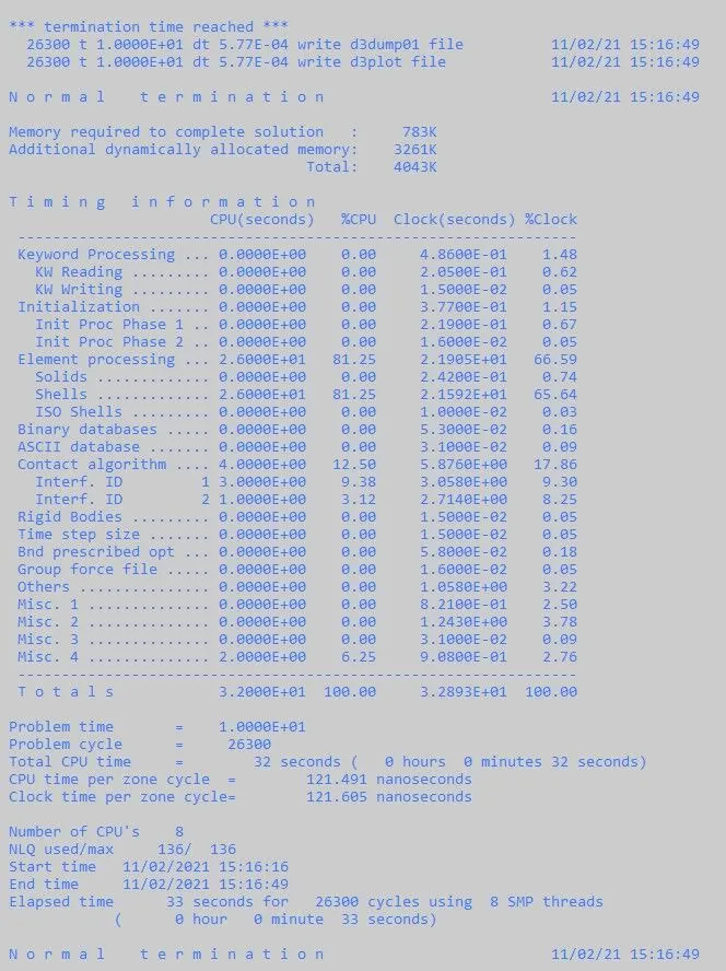
Fig 33: Successful completion of solving.
- Open a LS-PRE POST from the launch manager and open the LS-DYNA Binary plot (choose the D3PLOT file created) from the file menu.
- The model will be loaded the same as before, but we can access only the post-processing options from the right ribbon menu.
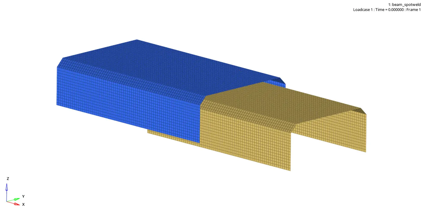
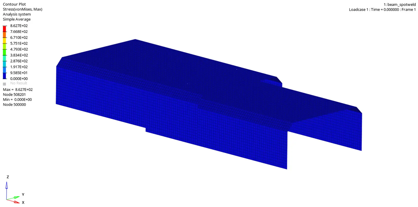
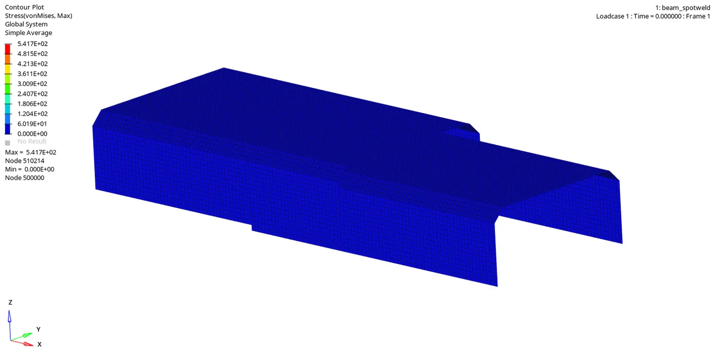
Beam Spotweld:
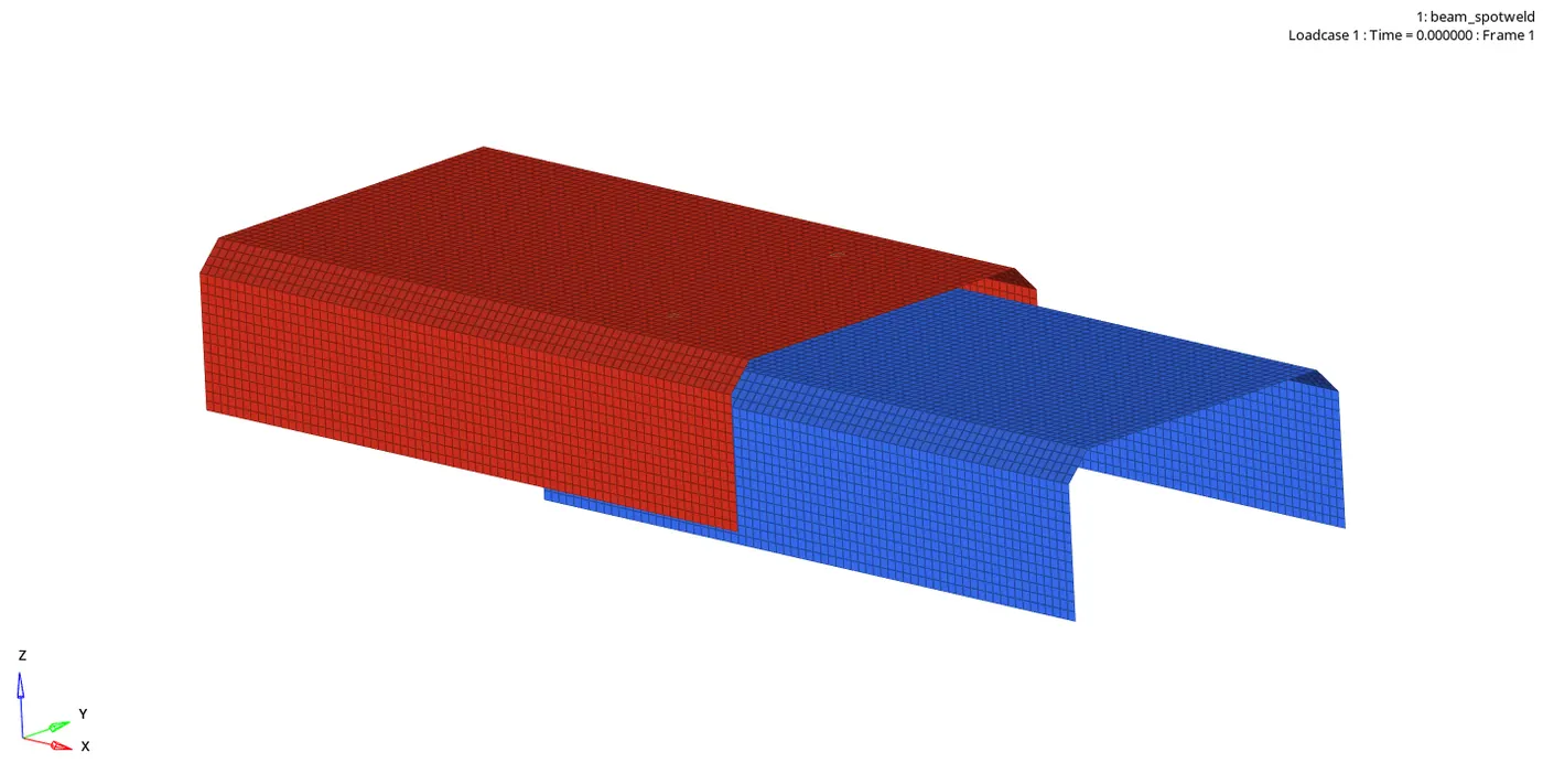
Solid Spotweld:
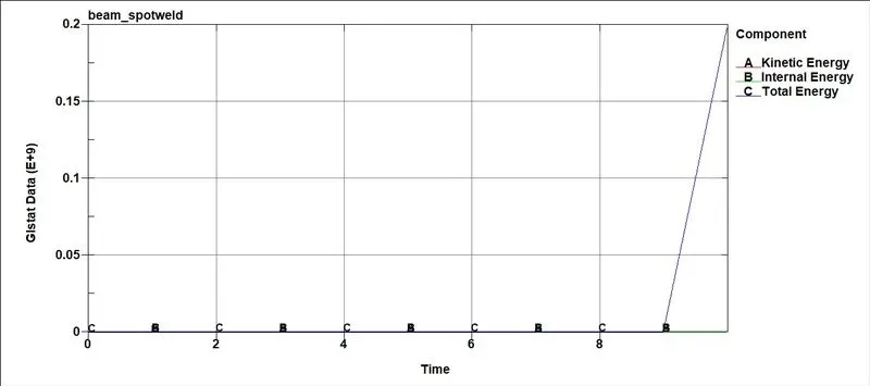
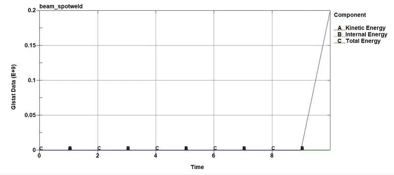
Energies:
Beam Spotweld:
Solid Spotweld:
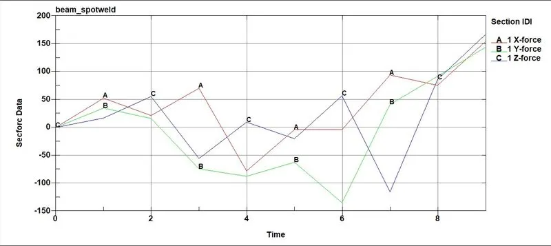
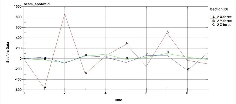
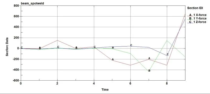
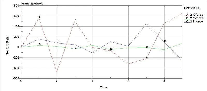
Sectional Forces:
Beam Spotweld:
Solid Spotweld:
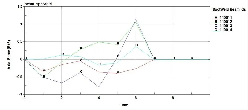
Axial Forces in the welds:
Beam Spotweld:
Solid Spotweld:
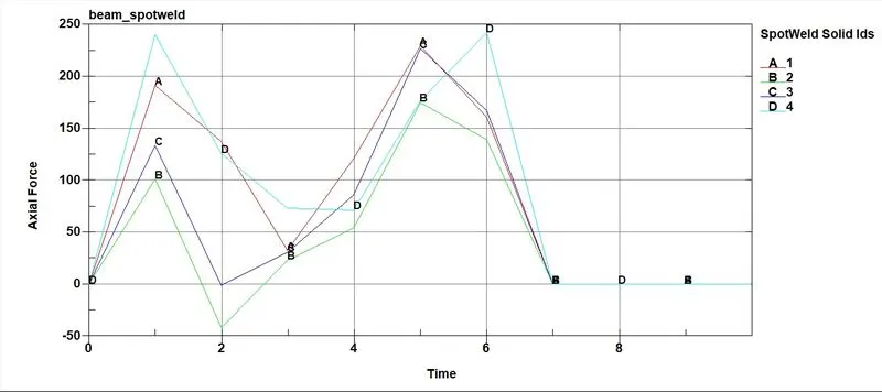
- The axial forces experienced by both the spotweld elements are displayed above. Beam experiences more axial load compared to the solid element. Since it is connected through one node, the weld is not stable.
Shear Forces in the welds:
Beam Spotweld:
Solid Spotweld:
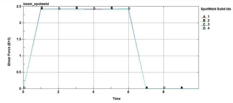
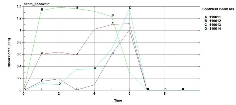
- The Shear stress experienced on each spotweld in both the cases is presented above. The solid element undergoes more shear load than the beam element because the solid element has four nodes in contact while the beam has only one. So compared to the beam, the solid element is more stable and is more suitable for modeling spotweld.
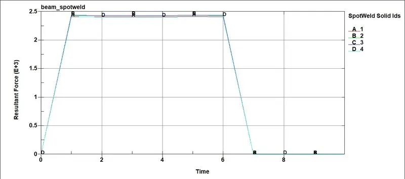
Resultant Forces in the welds:
Beam Spotweld:
Solid Spotweld:
Conclusions:
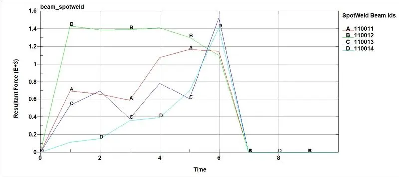
- Using a beam element for a spotweld, the axial load is higher than normal, leading to earlier failure if force-based failure criteria are used.
- Due to the high axial load in the beam element, localized stress is also higher. So solid element is more suitable for modeling the spotweld; it has four nodes in contact and better axial and shear capabilities.
- The 3D solid element is more suited to symbolize the spotweld better than the 1D beam element.