Week - 5 - Modelling Spotwelds
AIM :- Run a crash box simulation using beam spotweld and hexa solid spotweld and compare the results (Axial and shear forces).
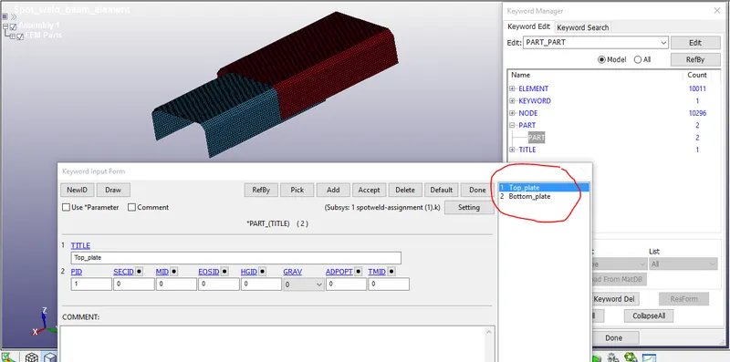
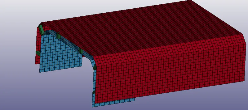
Procedure :- Import the given .k file in Ls-prepost, Rename the auto created parts names as Top_plate & Bottom_plate.
Modeling
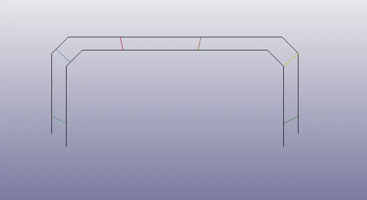
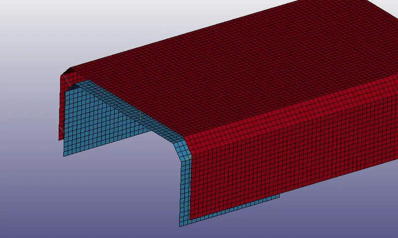
CASE -1 :- Beam elements for spotweld
- For easy selection put parts in wireframe mode and hide the unwanted elements using Blank option.
- To create beam element go to Mesh - elegen - beam (Two_node_sets)
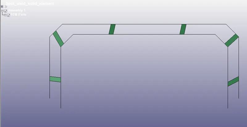
CASE -2:- Solid elements for spotweld
- To create Solid element go to element editing tools - create - hexa (select 8 nodes)
Material
Material card for Top and bottom plates
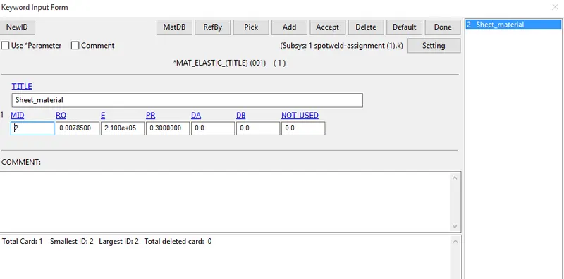
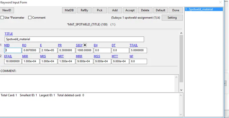
Material card for Beam & Solid elements
Section
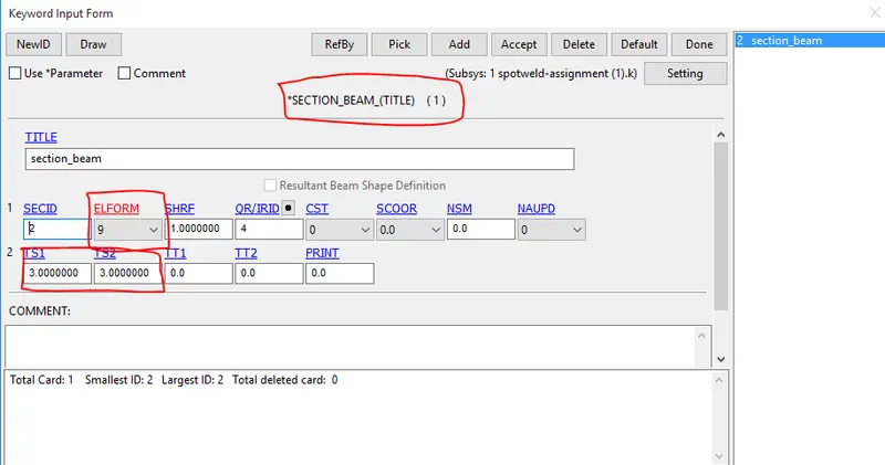
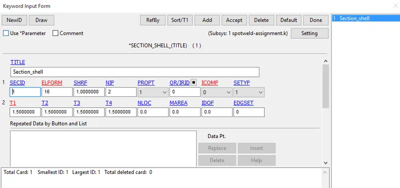
Case -1 :- section card for shell elements and beam elements
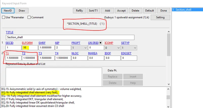
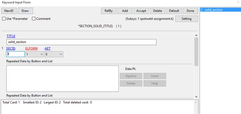
Case -2 :- section card for shell elements and Solid elements
Part
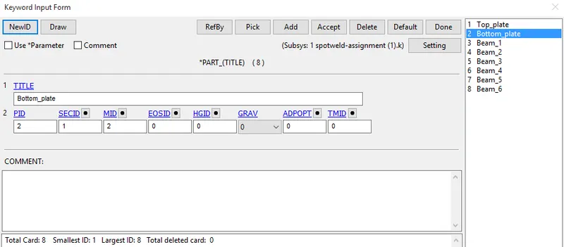
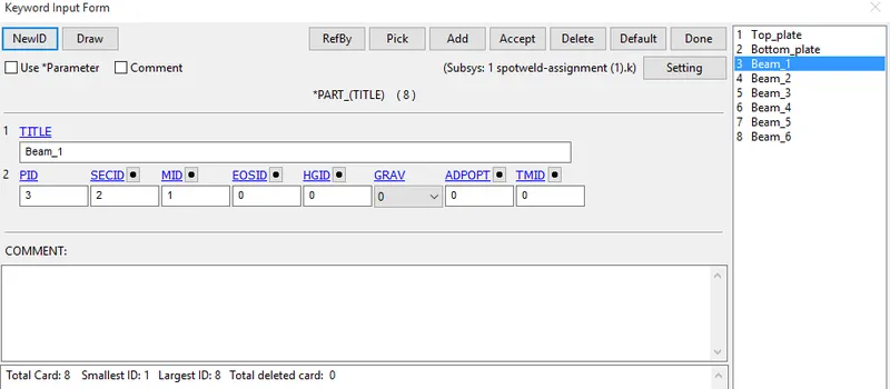
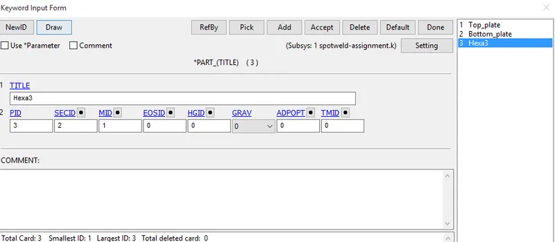
- Assign appropriate material and section in part for both cases
case-1 :- Top & bottom plates and 6 beam parts
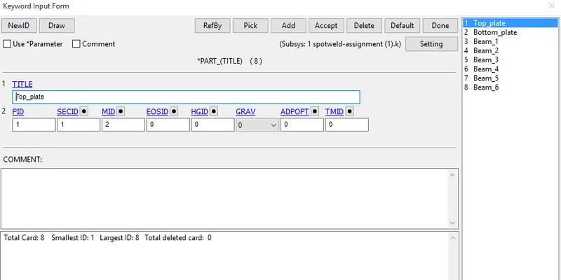
case 2:- Top & bottom plates and Hexa3 part
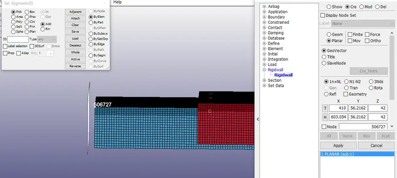
Boundary conditions
Rigid wall
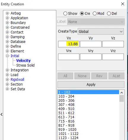
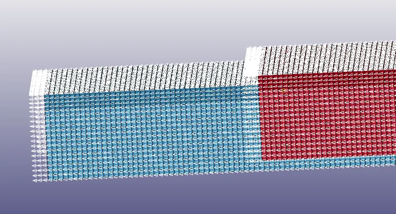
Initial velocity
Create Initial velocity for shell elements with 13.88mm/ms in X-direction
Contacts
Create 2 part sets, put top & bottom plate in one part set and all beam elements in another part set
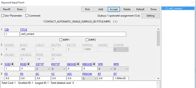
Self contact :- no need select MSID, put SSTYP as 2 and select top & bottom plate part set in SSID.
Tied contact :- select top & bottom plate part set as MSID and beam element part set as SSID
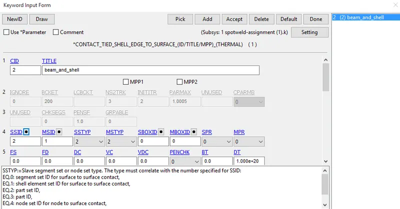
Tied contact for case2 :- select top & bottom plate part set as MSID and Hexa element part set as SSID
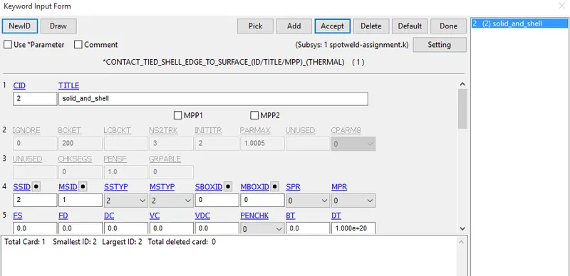
Database
- Create Database card for ASCII file and select glstat, matsum,nodout,swforc, sleout, secforc and rcforc with DT 0.5 and Binary d3plot with DT 0.5
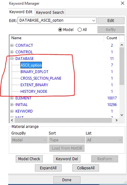
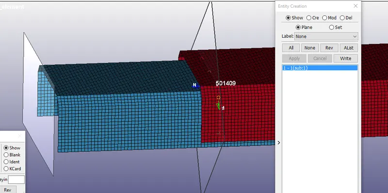
- create a cross section plane under database card at spotwelds location.
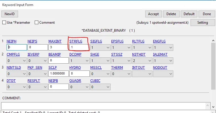
- To get directional strain, create a database card for extent_binary with STRFLG value as 1
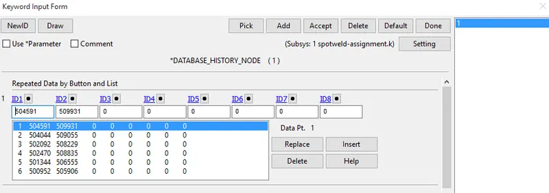
- Create a History Node keyword card under database, without History Node keyword card NODOUT in ASCII file will not give any result.
- Insert the beam element node IDs [n1&n2]
Control
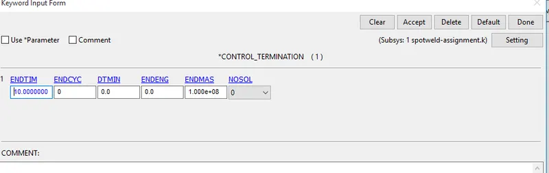
- Create a control termination card to specify end time for simulation.
Simulation
- save the keyword file in .k format and run simulation using Ls-Run.
Errors during simulation
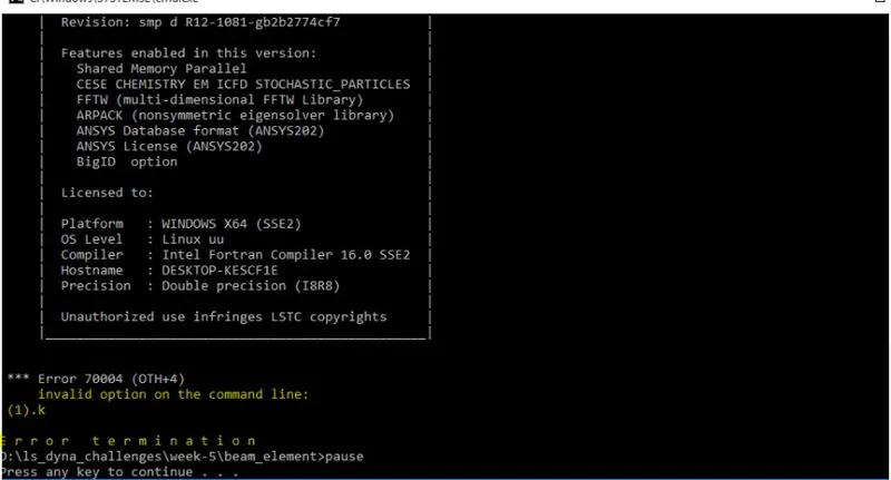
- Invalid option on the command line :- it means there is a space in file name or folder name, so remove the space with _ and run the simulation again.
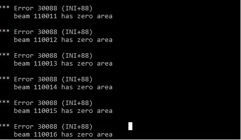
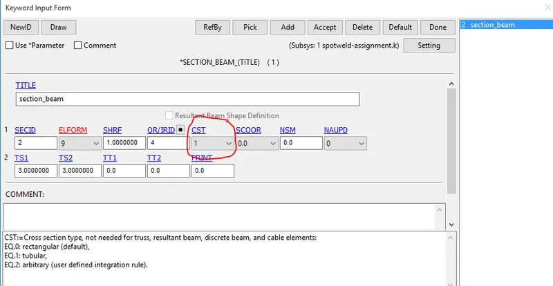
- beam has zero area :- to resolve this change CST to 1 in Section_beam.
Failure criteria of spotwelds
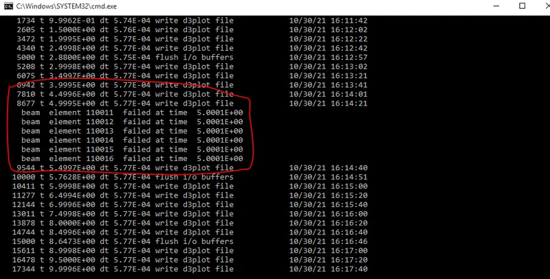
- The best simulation should have a failure at half of the termination time, here in this simulation our total run time is 10ms so in MAT_SPOTWELD card we mention Tfail=5ms
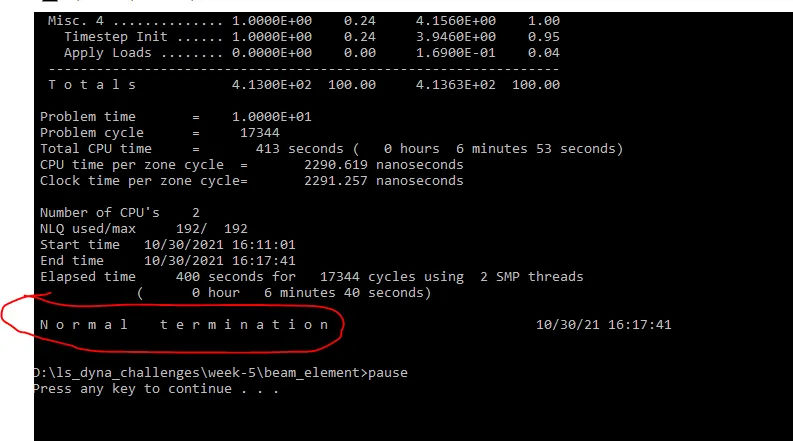
- make sure the termination should be normal
RESULTS
Animation of the final simulation
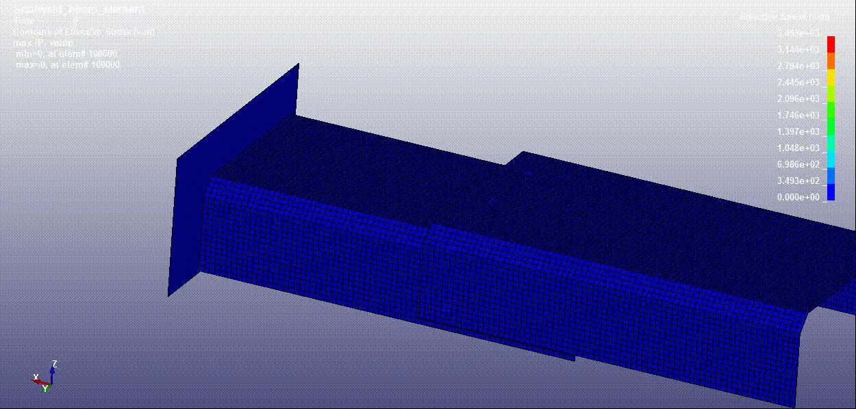
Von-misses stress comparision - beam and solid spotweld
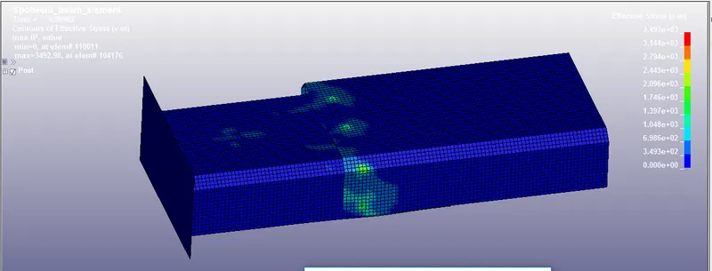
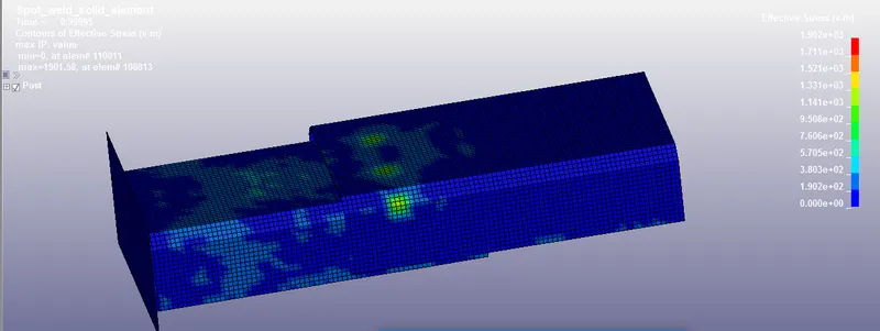
- it can be seen that the stress value is very high in beam_element spot weld(3.493e+3) compared to solid_element spot weld(1.902e+3)
Energy plots comparision - beam and solid spotweld
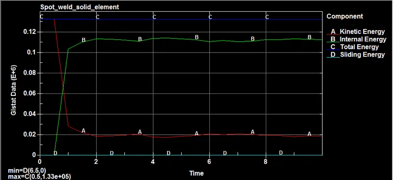
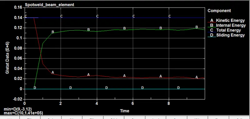
- The energy plot comprising of total energy, internal energy, kinetic energy and sliding energy were plotted for 1.2mm and 1.5mm thick crash boxes. from the graph kinetic energy decreses and internal energy increses as we expected from theory and total energy remains constant through out the simulation.
- Sliding energy is almost negligible.
- The energies are higher for beam_element (1.41e+05) compared to solid_element(1.33e+05)
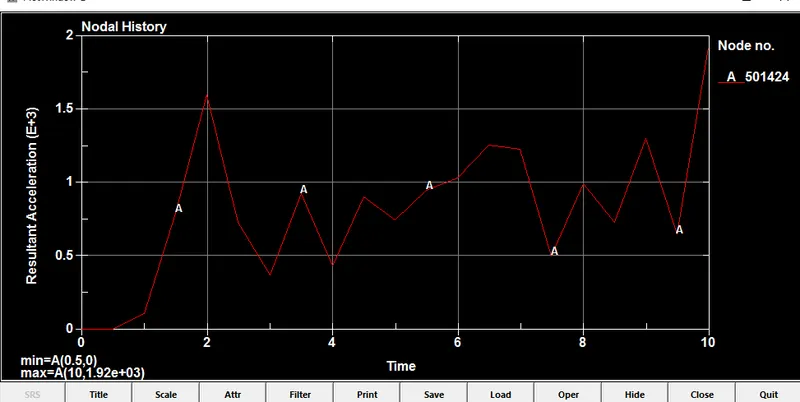
Acceleration comparision - beam and solid spotweld
spot weld type - solid
spot weld type - beam
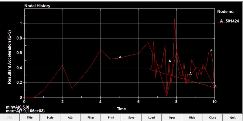
- Node #501424 in solid element spot weld has greater acceleration than beam element spot weld
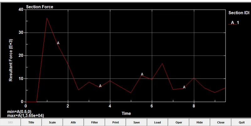
Section force comparision - beam and solid spotweld
spot weld type - solid
spot weld type - beam
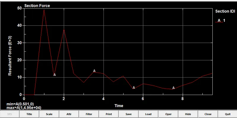
- Resultant force of a section force is higher in beam element spot weld than solid element spot weld
Axial force comparision - beam and solid spotweld
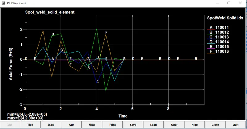
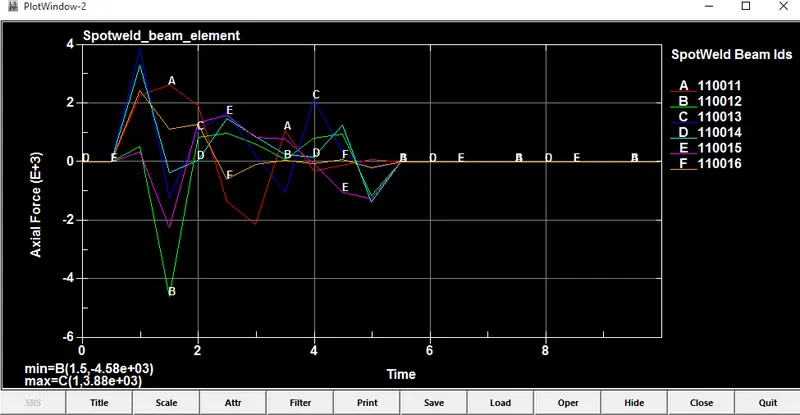
- beam element spotwelds experiences more axial force compare to the solid element. since it is connected through one node only the weld is not stable.
Shear force comparision - beam and solid spotweld
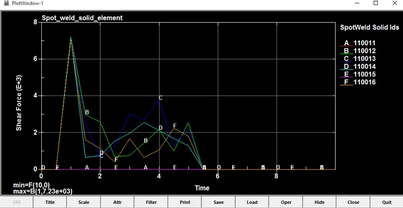
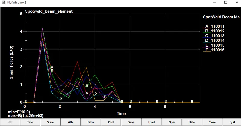
- solid element spotwelds experiences more shear force compare to the beam element beacuse the solid element has 4 nodes in contact while beam has only one node in contact. So the solid element is more stable and suitable for spot weld modelling.
Maximum directional stress and strain along the length of the component (X strain, Y strain etc)
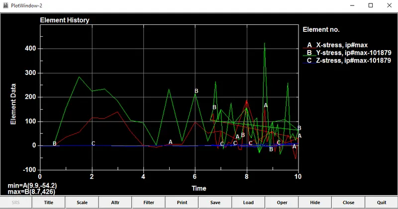
beam element - directonal stress
solid element - directonal stress
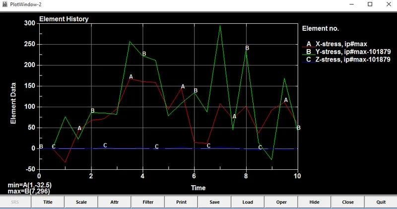
- Comparing directional stress for an element #101879, maximum stress generated in Y-direction for both cases and beam element spotwelds experiences more stress compare to the solid element.
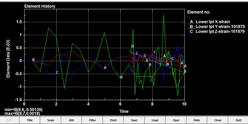
beam element - directonal strain
solid element - directonal strain
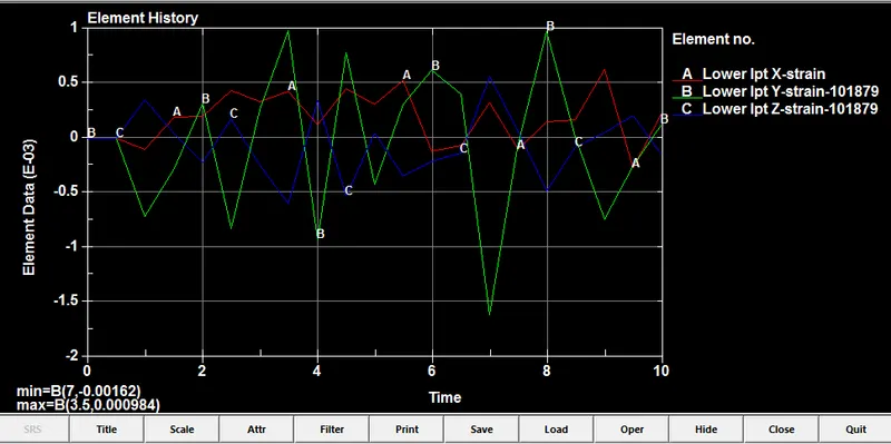
- Comparing directional strain for an element #101879, maximum strain generated in Y-direction for both cases and beam element spotwelds experiences more strain compare to the solid element.
CONCLUSION
- Performed a crash box simulation using beam spotweld and hexa solid spotweld and compared the results.
- Stress value is very high in beam_element spot weld(3.493e+3) compared to solid_element spot weld(1.902e+3)
- Before crash happening Kinetic energy is constant, when crash box hits the wall it deacclerate and Kinetic energy of crash tube is decreses.
- Internal energy of crash box increses after crash happens, Here K.E. converted as I.E. Following the law of conservation of energy theory.
- Total energy remains constant.
- Node #501424 in solid element spot weld has greater acceleration than beam element spot weld
- Resultant force of a section force is higher in beam element spot weld than solid element spot weld
- Solid element type spotwelds experiences more shear force and less axial force compare to the beam element beacuse the solid element has 4 nodes in contact while beam has only one node in contact.
- beam element spotwelds experiences more stress and strain compare to the solid element.
- Solid element is more stable and suitable for spot weld modelling.