Week - 5 - Modelling Spotwelds
SpotWelds
Objective
To simulate a crash test on the given assembly of components and compare the difference in using solid and 1D beam elements for spot Weld
Conditions
- Material for the assembly is steel
- Initial velocity for the assembly should be around 50 kmph
- The units system to be used is gm-mm-ms
Deliverables:
- Input .k file and output files (d3plot, glstat, sleout, rcforc)
- Animation of the final simulation
- Cross-sectional force generated in the middle of the assembly (along its length)
- Acceleration plot of a node in the middle of the assembly (along its length)
- Maximum directional stress and strain along the length of the assembly (X strain, Y strain etc)
- Plot of all energies (total, internal, kinetic, hourglass, sliding)
- Compare the accelerations and stress/strain plots of 1.2/1.5mm assembly.
Theory
Spotweld
Spot welding (or resistance spot welding) is a type of electric resistance welding used to weld various sheet metal products, through a process in which contacting metal surface points are joined by the heat obtained from resistance to electric current.
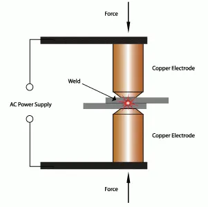
Advantages of spot welding
- Spot welding is a low-cost method of welding which makes it ideal for the automotive industry where cost savings are necessary.
- This type of welding does not require a highly skilled welder.
- With spot welding, there is no chance of the materials being distorted or warped.
- The joint that is created from spot welding is highly uniform.
- Spot welding allows for both automatic and semi-automatic welding.
- Spot welding can be achieved in quick succession, which helps improve productivity.
Disadvantages of spot welding
- While it is a low-cost method of welding the initial cost can be high due to the cost of necessary equipment, such as copper alloy electrodes.
- This technique is best suited for thin sheets of metal and may not work well on thick sheets of metal.
- Zinc-coated steels that are commonly used to make vehicle body parts degrade copper alloy electrodes, which can have an impact on productivity.
In ls-dyna, there are 4 different ways to model a spot weld.
- 1D Beam Elements
- 3D Hexa Elements
- Constrained Spot weld
- Constrained weld Spot
Mat100 Spot Material Model
The material model applies to beam element type 9 and solid element type 1. The failure models apply to both beam and solid elements. In the case of solid elements, if hourglass type 4 is specified then hourglass type 4 will be used, otherwise, hourglass type 6 will be automatically assigned. Hourglass type 6 is preferred.
The beam elements, based on the Hughes-Liu beam formulation, may be placed between any two deformable shell surfaces and tied with constraint contact, *CONTACT_SPOTWELD, which eliminates the need to have adjacent nodes at spot weld locations. Beam spot welds may be placed between rigid bodies and rigid/deformable bodies by making the node on one end of the spot weld a rigid body node which can be an extra node for the rigid body, see *CONSTRAINED_EXTRA_NODES_OPTION. In the same way, rigid bodies may also be tied together with this spot weld option. This weld option should not be used with rigid body switching. The foregoing advice is valid if solid element spot welds are used; however, since the solid elements have just three degrees of freedom at each node, *CONTACT_TIED_SURFACE_TO_SURFACE must be used instead of *CONTACT_SPOTWELD. In flat topologies, the shell elements have an unconstrained drilling degree-of-freedom which prevents torsional forces from being transmitted. If the torsional forces are deemed to be important, brick elements should be used to model the spot welds. Beam and solid element force resultants for MAT_SPOTWELD are written to the spot weld force file, swforc, and the file for element stresses and resultants for designated elements, elout.
It is advisable to include all spot welds, which provide the slave nodes, and spot welded materials, which define the master segments, within a single *CONTACT_- SPOTWELD interface for beam element spot welds or a *CONTACT_TIED_SURFACE_TO_SURFACE interface for solid element spot welds. As a constraint method these interfaces are treated independently which can lead to significant problems if such interfaces share common nodal points. An added benefit is that memory usage can be substantially less with a single interface.
Procedure
- After Importing the keyword file, we can start by applying the boundary conditions
Beam Elements
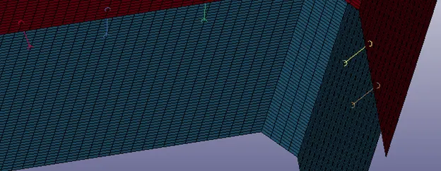
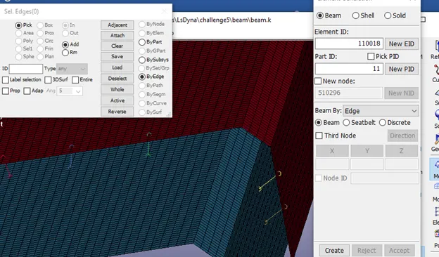
Create 1 D beam elements along the same line to represent spot-welds using element generation in the mesh toolbar.
Hexa Element
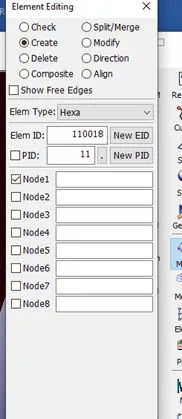
Using Element Edit, create a Hexa element on the same location as the beam elements.
Contacts
- Define the self contact using Automatic Single Surface Keyword
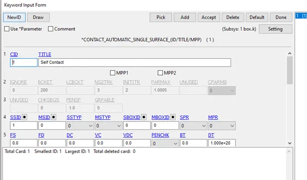
The slave nodes include all the nodes of the assembly.
Tied Nodes to Surface
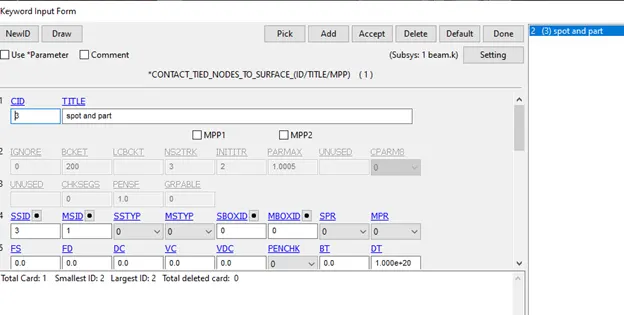
Master Nodes are the assembly nodes
Slave nodes are the Beam/Hexa elements for spot welds
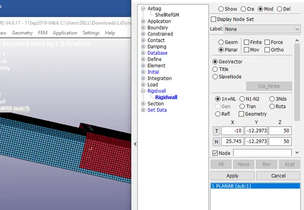
Rigid wall
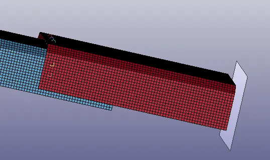
- A rigid wall can be created on either side of the assembly.
- Care should be taken that the normal of the rigid wall is opposite to that of the crash box
- Create the rigid wall using the create entity option
Initial Velocity
- The Initial velocity, given as 50Kmph is converted into 13.88mm/ms
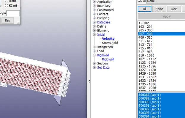
- Apply this velocity to the x-axis to all the elements using the create entity option
Material
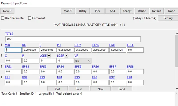
- In the keyword manager, create a mat024 Linear Plastic material card and add the appropriate values in the proper units
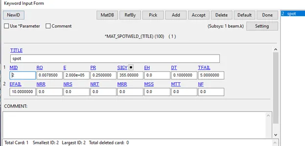
- For the spotweld, create a mat100 material.
- We are approximating the Etan Value to 1% of Youngs Modulus.
- We use a Tfail of 5 as after the impact happens, the spot weld should almost immediately fail.
- Since we do not have any material properties to assign we use Tfail instead.
Section
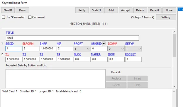
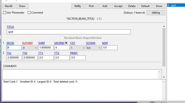
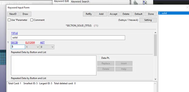
- Create a section shell, beam and solid keyword using the keyword manager.
- We will be using the Belytschko-Tsay (default) element formulation.
- Other than that we will be using the default values given.
Hourglass
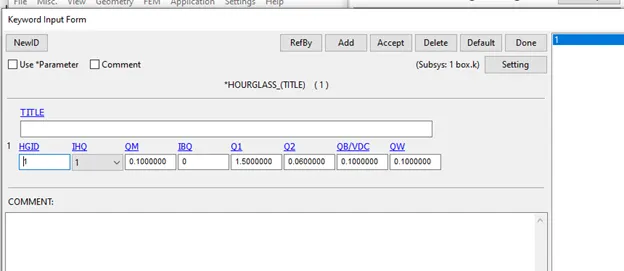
- Create an hourglass keyword as shown.
Creating Section and Node
- In create Entity Option, under Database
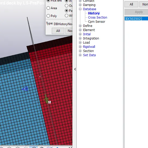
- Create a history on a node on the top portion of the crash box and a cross-section in the middle.
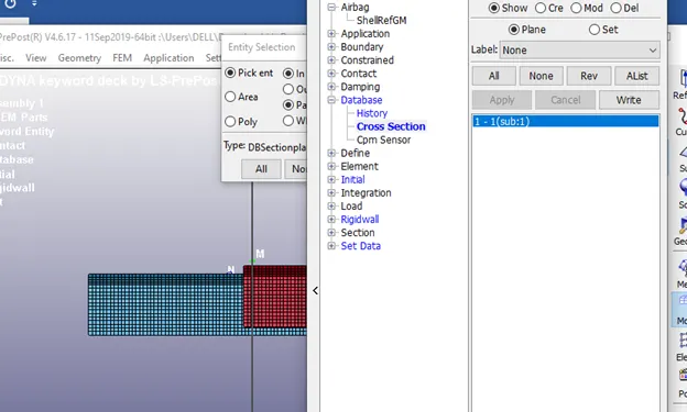
Output Files
- In database, create the d3plot and Ascii keywords
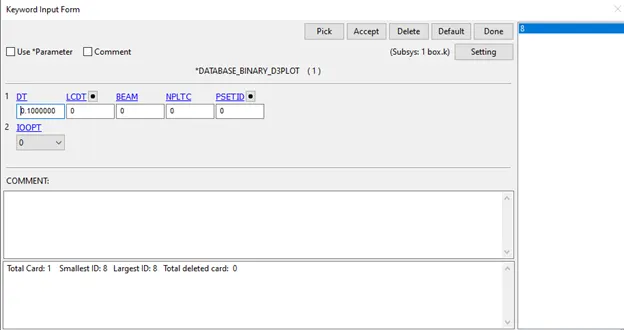
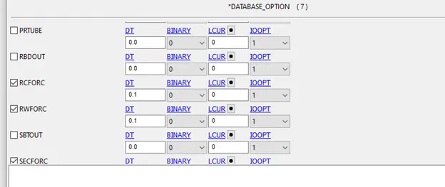
- In Ascii,enable Glstat,Matsum,Nodout,Rcforc,Rwforc,SecForc and Sleout
Control
- Create a Control Termination Keyword
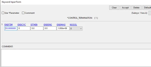
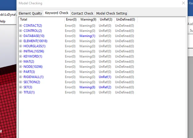
Check the keywords using the model checker for errors
No errors only warnings and unref.
After this run the simulation using the ls Dyna solver
Make sure that the folder has no spaces and the termination is normal termination.
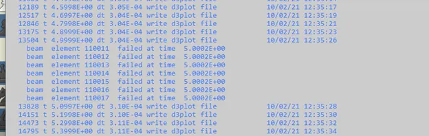
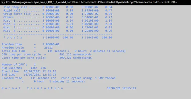
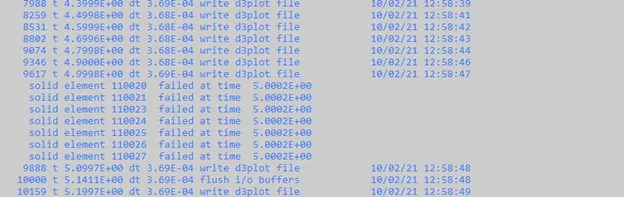
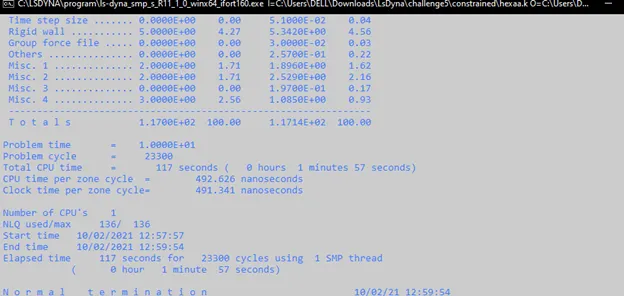
The time taken for Hexa spot Welds is less due to the element formulation resulting in fewer integration points compared to Elform 9 used in the Beam section.
Post Processing
Beam
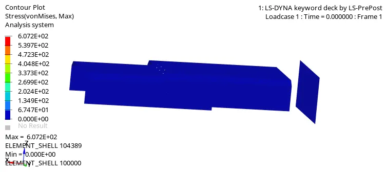
Since, we are using 1D beam elements only a single set of nodes are connected per beam. This leads to poorer transfer of forces when compared to the 3D Hexa elements which connect 8 nodes together.
HEXA
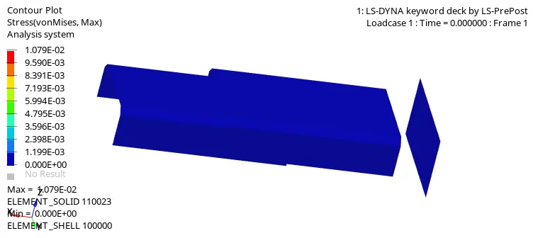
On comparing this to the assembly using hexa elements, it can be seen that the deformation pattern is significantly different. This is due to the fact that in Hexa elements more nodes are connected, thus leading to better transfer of forces
Other factors contributing to this difference are the Area of Cross-section and Element Formulation used for Beam and Hexa elements.
Beam element
Energy Graphs
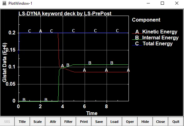
In the beginning, Kinetic Energy is high due to the initial velocity,as impact happens it gets converted to Internal Energy.
After impact, most of the kinetic energy is converted to internal energy.
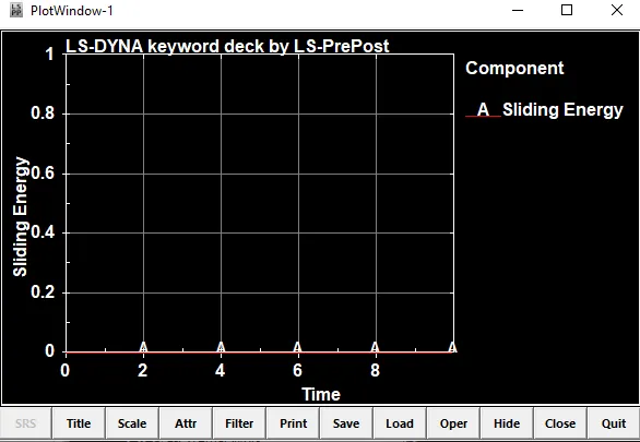
The contact energy is 0 during the simulation.This indicates that elements do not tend to penetrate due to deformation.
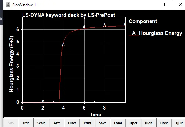
Hourglass energy is in a significantly lower range compared to the total energy (10^3 compared to 10^6) and thus the Total Energy graph seems to be in a straight line.
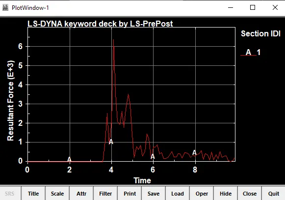
There is a high spike in sectional force at point of impact after which it decreases almost immediately.
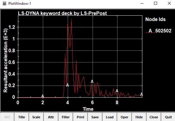
The acceleration reaches its peak during the initial impact.
It varies a bit during the simulation indicating vibration of elements.
Axial and Shear Forces
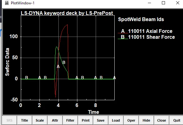
Axial force peaks at 129.673g*mm/ms^2 and has a minimum of -42.8005g*mm/ms^2
Shear force peaks at 77.2879g*mm/ms^2
Hexa Element
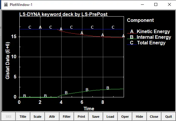
In the beginning, Kinetic Energy is high due to the initial velocity,as impact happens some amount of Kinetic Energy gets converted to Internal Energy.
It is higher than Internal energy as there is a lot of vibration of elements due to deformation.
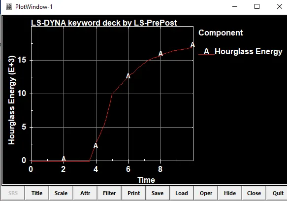
Hourglass energy is in a significantly lower range compared to the total energy (10^3 compared to 10^6) and thus the Total Energy graph seems to be in a straight line.
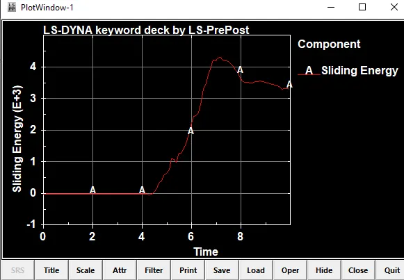
The contact energy increases steadily after impact.This indicates that the elements tend to penetrate more as the simulation progresses till 7ms after which it begins to decrease.
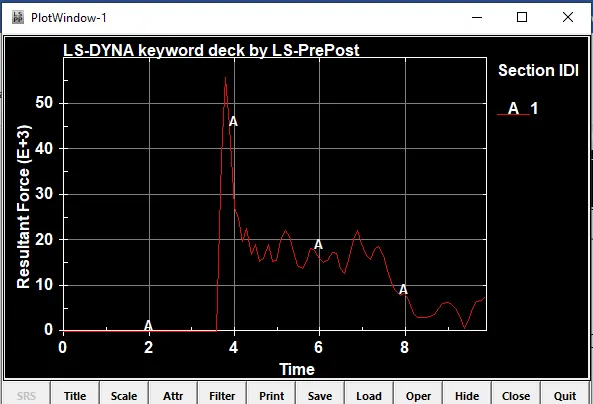
There is a high spike in sectional force at the point of impact.
Further spikes can be attributed to the deformation of elements, after which it tends to zero indicating complete deformation.
The cross sectional forces are higher in these cases indicating better transfer of forces.
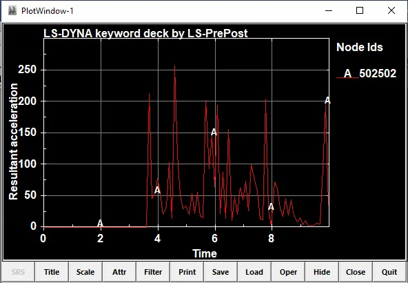
The acceleration spikes at the point of impact. It varies rapidly throughout the simulation after impact signifying deformation of elements and vibrations.
Axial and Shear Forces
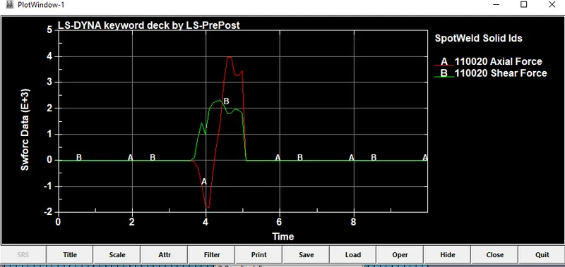
Axial Force peaks at 4000 g*mm/ms^2 and has a minimum of -1819.15 g*mm/ms^2
Shear Force peaks at 2354.66 g*mm/ms^2
Note:g*mm/ms^2 is also 1 N
It can be observed that the forces experienced in the hexa element case is significantly higher,
This can be due to the stiffer element formulation of hexa elements given displacement is constant.
Learning Outcomes
- Modelling spot Welds in ls dyna
- Impact of 1d and 3d elements
Conclusion
Spot welding offers several benefits to the automotive industry. For starters, it is a low-cost method of joining different sheets of metal. Also, it can work with various metals. Thus, can be used for welding aluminium as well as steel sheets.
In this project, we modelled spotwelds using 1D and 3D elements and observed the differences between the two. While 3D elements give a more accurate result, the increase in computational power and time should be taken into account by the engineer while setting up the simulation. The effects of Element Formulation and Area of cross-section on the results are also taken into account as they play a significant role in analysis.