Week 5 Fuel cell powered model
AIM:- simulating the 6 kW 45 Vdc Fuel Cell Stack built-in model in Matlab and explain
For the 6 kW 45 Vdc Fuel Cell Stack built-in model in Matlab,
a.Explain the working priniciple of the model in detail
b.Simulate the model and explain the results
c.Explain the voltage and current characteristics in your resultant graph
What is a Fuel Cell ?
Fuel cells require a continuous input of fuel and an oxidizing agent (generally oxygen) in order to sustain the reactions that generate the electricity. Therefore, these cells can constantly generate electricity until the supply of fuel and oxygen is cut off.Despite being invented in the year 1838, fuel cells began commercial use only a century later when they were used by NASA to power space capsules and satellites. Today, these devices are used as the primary or secondary source of power for many facilities including industries, commercial buildings, and residential buildings.
Working principal of fuell cell ?
A fuel cell works on the principal of electrochemical cells, which consists of a cathode, an anode, and an electrolyte. In these cells, the electrolyte enables the movement of the protons.
What what is an electrochemical cell?
An electrochemical cell is a device that can generate electrical energy from the chemical reactions occurring in it, or use the electrical energy supplied to it to facilitate chemical reactions in it. These devices are capable of converting chemical energy into electrical energy, or vice versa. A common example of an electrochemical cell is a standard 1.5-volt cell which is used to power many electrical appliances such as TV remotes and clocks.
Working of Fuel Cell ?
The reaction between hydrogen and oxygen can be used to generate electricity via a fuel cell. Such a cell was used in the Apollo space programme and it served two different purposes – It was used as a fuel source as well as a source of drinking water (the water vapor produced from the cell, when condensed, was fit for human consumption).The working of this fuel cell involved the passing of hydrogen and oxygen into a concentrated solution of sodium hydroxide via carbon electrodes. The cell reaction can be written as follows:
Cathode Reaction: O2 + 2H2O + 4e– → 4OH–
Anode Reaction: 2H2 + 4OH– → 4H2O + 4e–
Net Cell Reaction: 2H2 + O2 → 2H2O
However, the reaction rate of this electrochemical reaction is quite low. This issue is overcome with the help of a catalyst such as platinum or palladium. In order to increase the effective surface area, the catalyst is finely divided before being incorporated into the electrodes.
A block diagram of this fuel cell is provided below.
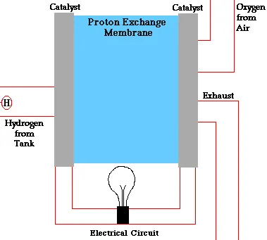
The efficiency of the fuel cell described above in the generation of electricity generally approximates to 70% whereas thermal power plants have an efficiency of 40%. This substantial difference in efficiency is because the generation of electric current in a thermal power plant involves the conversion of water into steam, and the usage of this steam to rotate a turbine. Fuel cells, however, offer a platform for the direct conversion of chemical energy into electrical energy.
Types of Fuel Cells
- Polymer Electrolyte Membrane (PEM) Fuel Cell
- Phosphoric Acid Fuel Cell
- Solid Acid Fuel Cell
- Alkaline Fuel Cell
- Solid Oxide Fuel Cell
- Molten Carbonate Fuel Cell
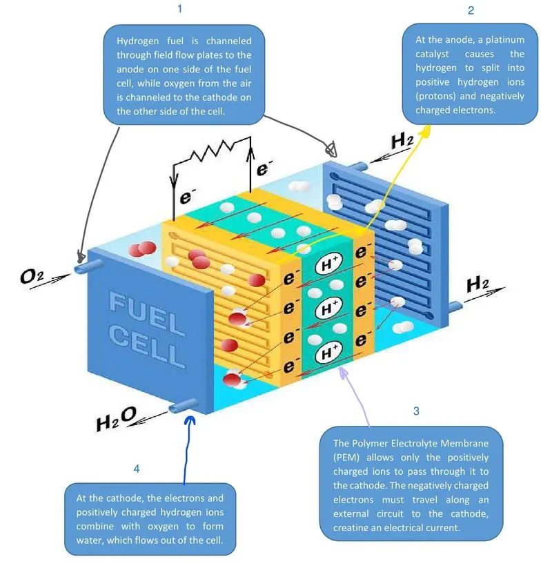
The Polymer Electrolyte Membrane (PEM) Fuel Cell
These cells are also known as proton exchange membrane fuel cells (or PEMFCs).
The temperature range that these cells operate in is between 50oC to 100oC
The electrolyte used in PEMFCs is a polymer which has the ability to conduct protons.
A typical PEM fuel cell consists of bipolar plates, a catalyst, electrodes, and the polymer membrane.
Despite having eco-friendly applications in transportation, PEMFCs can also be used for the stationary and portable generation of power.
Phosphoric Acid Fuel Cell
These fuel cells involve the use of phosphoric acid as an electrolyte in order to channel the H+
The working temperatures of these cells lie in the range of 150oC – 200oC
Electrons are forced to travel to the cathode via an external circuit because of the non-conductive nature of phosphoric acid.
Due to the acidic nature of the electrolyte, the components of these cells tend to corrode or oxidize over time.
Solid Acid Fuel Cell
A solid acid material is used as the electrolyte in these fuel cells.
The molecular structures of these solid acids are ordered at low temperatures.
At higher temperatures, a phase transition can occur which leads to a huge increase in conductivity.
Examples of solid acids include CsHSO4 and CsH2PO4 (cesium hydrogen sulfate and cesium dihydrogen phosphate respectively)
Alkaline Fuel Cell
This was the fuel cell which was used as the primary source of electricity in the Apollo space program.
In these cells, an aqueous alkaline solution is used to saturate a porous matrix, which is in turn used to separate the electrodes.
The operating temperatures of these cells are quite low (approximately 90oC).
These cells are highly efficient. They also produce heat and water along with electricity.
Solid Oxide Fuel Cell
These cells involve the use of a solid oxide or a ceramic electrolyte (such as yttria-stabilized zirconia).
These fuel cells are highly efficient and have a relatively low cost (theoretical efficiency can even approach 85%).
The operating temperatures of these cells are very high (lower limit of 600oC, standard operating temperatures lie between 800 and 1000oC).
Solid oxide fuel cells are limited to stationary applications due to their high operating temperatures.
Molten Carbonate Fuel Cell
The electrolyte used in these cells is lithium potassium carbonate salt. This salt becomes liquid at high temperatures, enabling the movement of carbonate ions.
Similar to SOFCs, these fuel cells also have a relatively high operating temperature of 650oC
The anode and the cathode of this cell are vulnerable to corrosion due to the high operating temperature and the presence of the carbonate electrolyte.
These cells can be powered by carbon-based fuels such as natural gas and biogas.
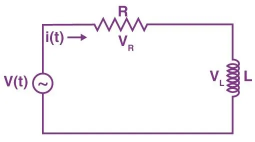
WHAT IS RL CURCIT ?
RL Circuits (resistor – inductor circuit) also called RL network or RL filter is a type of circuit having a combination of inductors and resistors and is usually driven by some power source. As such, an RL circuit has the inductor and a resistor connected in either parallel or series combination with each other. They are either driven by the current (parallel) or a voltage (series) source. Besides, the resistor (R), inductor (L), and capacitor(C) form the basic passive linear circuit elements. They can form an electrical circuit in four different ways like the RC circuit, the LC circuit and the RLC circuit.
6 kW 45 Vdc Fuel Cell Stack model
The nominal Fuel Cell Stack voltage is 45Vdc and the nominal power is 6kW. The converter is loaded by an RL element of 6kW with a time constant of 1 sec. During the first 10 secs, the utilization of the hydrogen is constant to the nominal value (Uf_H2 = 99.56%) using a fuel flow rate regulator. After 10 secs, the flow rate regulator is bypassed and the rate of fuel is increased to the maximum value of 85 lpm in order to observe the variation in the stack voltage. That will affect the stack efficiency, the fuel consumption and the air consumption.
WORKING OF THE MODEL.
first the input is taken from the flow rate selector which goes in fwel cell stack which is combined with boost converter and input to the boost converter is the RL curcit .
why this arrangement because the load produce by the RL curcit needed to be same as the electricity produced by the FEUL CELL STACK this is been done by the BOOST CONVERTER. if this is not equal then the electricity will be produced by the will not be capable to move the load further.
BLOCK USED
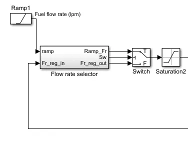
first the input is given through the flow rate selector which provides the rate of flow per liter with the regulation also means according tho thr requlation is increased the flow rate will be supplyed. which further goes to swich.
switch is used to change the fuel flow rate according according to the condition.
saturation block is used to make sure the the maximum limit of passing the flow rate will be 85 and the minimul limit will be 0.
FUEL CELL STACK
this block works as a fuel cell block which takes the low rate in the form of hydrogen and provides the current and voltage at the output. if we see the paramaters inside it.
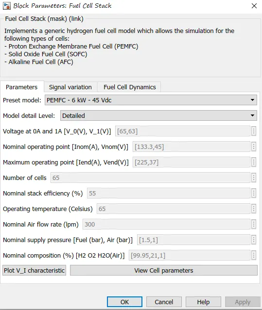
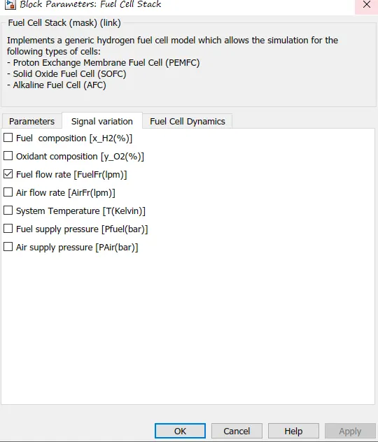
here we in increase inputt the fuell cell stack as first we are providing only the fuel flow rate but we can also provide what will be the air flow rate for the oxygen supply.
air pressure ,fuel composition etc.
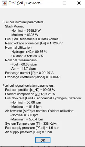
this will the automatic parameters selected on which the output results will tbe given to us.
DC/DC CONVERTER
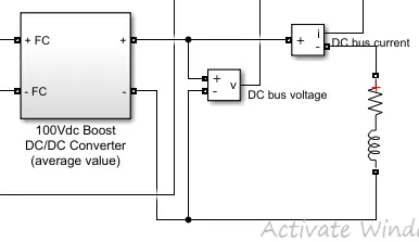
A boost converter (step-up converter) is a DC-to-DC power converter that steps up voltage (while stepping down current) from its input (supply) to its output (load).
this boost converter is connected with the fuel cell stack.
on the other end of the boost converter RL curcit is added.
RL CURCIT
The Series RLC Branch block implements a single resistor, inductor, or capacitor, or a series combination of these. Use the Branch type parameter to select elements you want to include in the branch.Negative values are allowed for resistance, inductance, and capacitance.
FLOW RATE REGULATOR
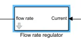
flow rate regulator wil work on the base of the current which is prduced by the fuell cell stack.
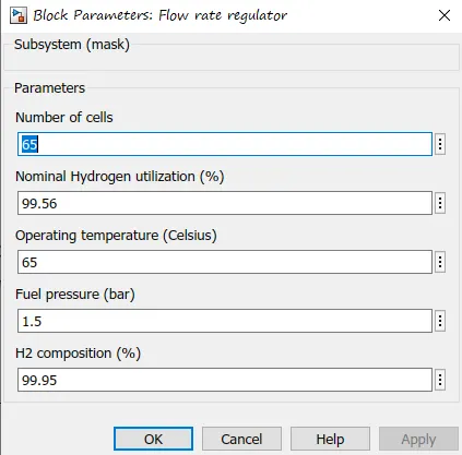
this is the given parameter on which the flow rate regulator will be working on.
out put plot
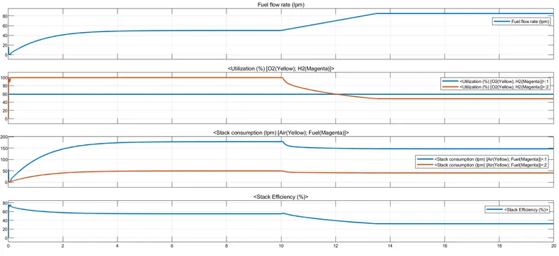
- in first plot we can see the fuel rate is made constant for the first half at and after10 sec fuel rate is increased to 85.
- due to increase in flow rate the hydrogen utilization is reduced while the oxygen utilization was constant this is due to the input limitation in fuel cell stack.as we are providing only input as hydrogen and the oxygen values are automatic been taken so it does not mater how much flow rate is changed the oxygen will be taken as a constant for all values
- due to increase in flow rate the air consumption is reduced and fuel consumption is also reduced.
- as we increase the flow rate the efficiency of the stack is also reduces .means as flow rate is increased the voltage is incrases and current will also change which causes efficiency go down. this show as that at higher rate the fuel stack efficiency will be low.
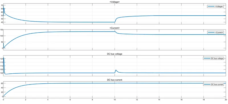
the first two plot are of output of fuel stack and 3,4 plot are of the dc boost converter.
- the movement it starting the voltage is adjusted to 45 because this is an RL curcit an exponontial rise will be seen at current and so the exponential fall in the current can be seen and after 10 sec the flow rate is increased due to which increase in the voltage can bee seen.
- similaly the current will be seen in as reverse of the voltage due to invertion al proportion of voltage
- at the load side due to dc / dc boost converter we will not get much fluctuation little fluctuation can be seen after 0 sec due to increase in flow rate.
- due to the boost converter the current isa also constant which mean the power flow is also constant .
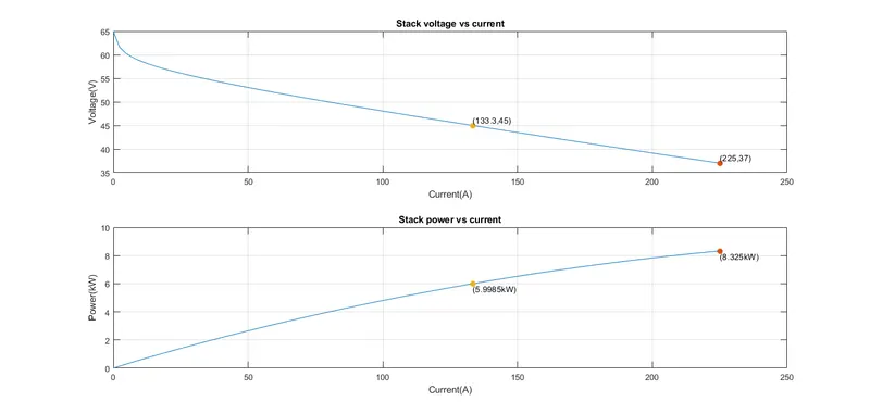
this above graph is for the fuel cell stack which shows the current vs voltage and power vs current.
as current is increasing the voltage is dropping chich shows that the increase in current means increase in power.
refrences:-
https://byjus.com/chemistry/fuel-cell/
https://byjus.com/jee/rl-circuit/
THANK YOU