Week 5 Challenge : Surface wrap on Automotive Assembly
Aim: To perform topological clean-up as required for the given three geometries and complete surface wrapping for the merged model.
Objective:
- To check for the geometrical errors and perform necessary topological clean-up for individual parts.
- Merge the three geometries into a single geometry.
- Perform surface wrapping for the merged geometry.
Terminology: The following options are used to complete our objective.
- PID – This function facilitates property management. A list of the properties existing in the file is available.
- Fitted – The FITTED option is used for the definition of a non-planar Face. The created Face fits to the selected boundaries.
- Merge – This function activates the file manager in order to merge ANSA files or neutral format files to the currently loaded file in ANSA.
- Compress – This function is used to compress an ANSA database. This function relieves the database from unwanted information.
- Wrap – The Wrap [Constant Length] is a very fast algorithm used for the creation of a watertight triangular surface mesh of uniform size length from an assembly of unconnected or intersecting components.
- Octree – This algorithm creates a cube around the geometry and splits the cube over and over until it reaches the given mesh requirements. This mesh is projected onto the geometry i.e., a top-down meshing approach.
Procedure:
The process can be done in three steps as mentioned in the objective.
Step 1:
We import the file into the ANSA software from the PC.
File -> Open -> Browse and select the file.
The model is displayed in wire frame mode by default. We change it to shadow mode.
Geometrical clean-up for engine:
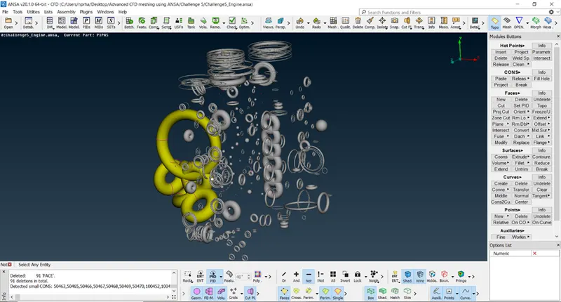
The imported engine file has a lot of unwanted standalone and overlapping components as shown in the figure. These parts have no significance with the geometry and need to be deleted.
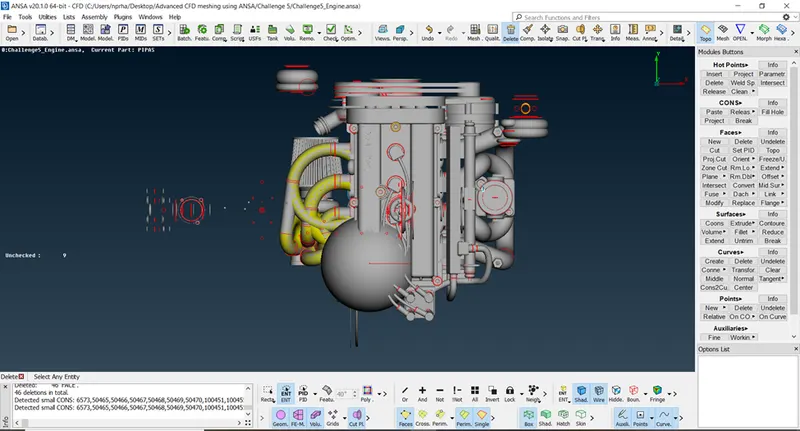
In the following two figures, we can see that we delete all the unwanted surfaces that are outside the engine geometry.
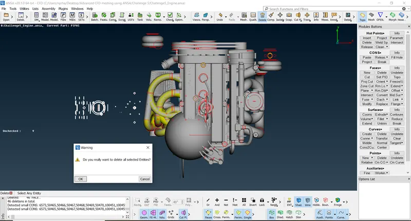
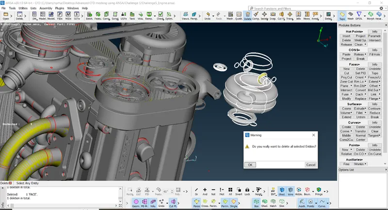
We can see a few unchecked faces in the geometry as displayed on the left side of our workspace. We can use Show Only option to isolate these surfaces and delete them as shown.
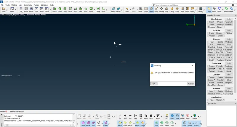
We can hide the parts of the engine using PID selection to isolate all the unwanted surfaces within the engine geometry. We can see a lot of donut and ring-shaped surfaces with no significance within the engine as shown in the following figure. All these surfaces are deleted.
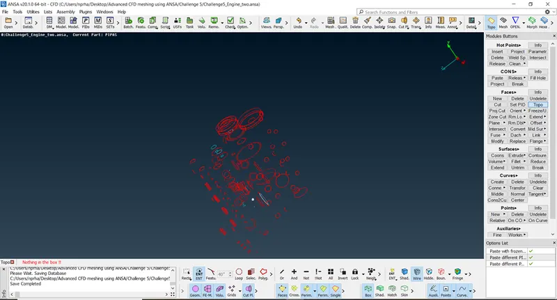
Once we are done with unwanted surface deletion, we see a lot of geometrical errors in the figure. Since we are going to perform surface wrap over the model, we need not resolve the errors in the interior part of the engine. We perform topological clean-up on the external surfaces and save the model.
Geometrical clean-up for gear box:
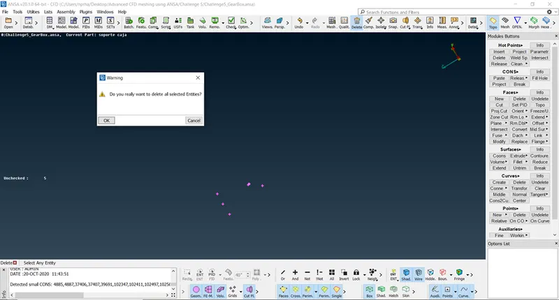
We import the gear box ANSA file. We can see a few unchecked surfaces in the geometry. We can delete them using Show Only option as shown in the figure.
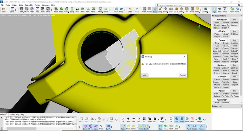
We find donut shaped unwanted structures in this model as well. We would delete these surfaces as shown in the following two figures.
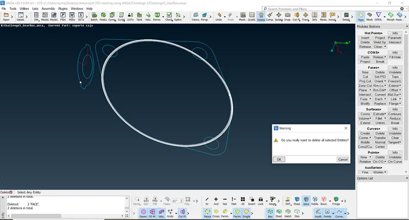
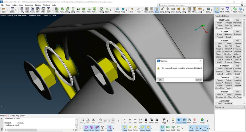
The over lapping surfaces are also spotted and deleted. We can ignore the internal geometrical errors for gear box. We will save this model.
Geometrical clean-up for transmission:
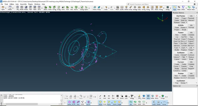
We then import transmission ANSA file. We can see a lot of triple cons in the model as shown in the figure.
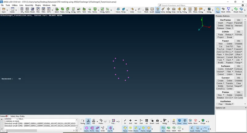
We isolate and delete the unchecked surfaces as shown in the figure.
The unwanted donut shaped structures are found and deleted as shown in the following two figures.
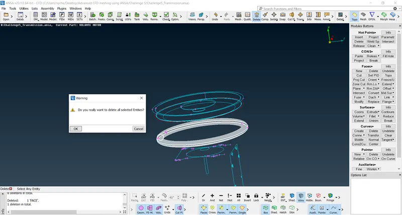
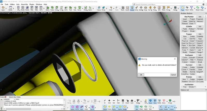
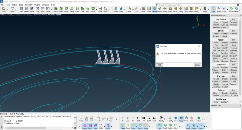
The unwanted surfaces in the geometry are also deleted as shown in the following figure.
Step 2:
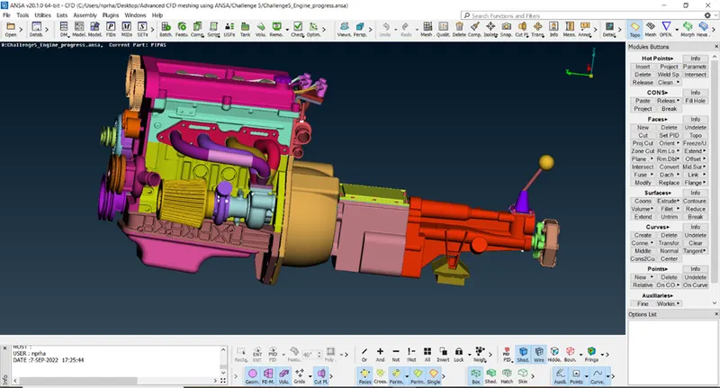
We will now proceed to merge the engine and gear box to this transmission model. We can use File -> Merge option to select the engine and gear box files we saved earlier and press OK. The three components will get merged as shown in the following figure.
Step 3:
We can see many holes in the exterior part of the geometry. We need to close these holes to have uniform surface wrap over the geometry. If we don’t close the holes, the algorithm would create the mesh in these holes also and the surface wrap might not be smooth.
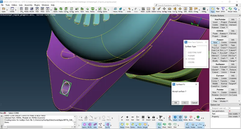
Since we deleted many unwanted surfaces, many PID’s will get deleted. We use Compress tool to remove the unwanted PID names in PID manager.
We would perform surface wrap using Mesh -> Octree -> Wrap -> Constant Length.
We will select New -> CFD Parameters and specify target length as 3mm and shell type as Trias.
We select contents and select all PID’s. We use Run to start the surface wrapping process.
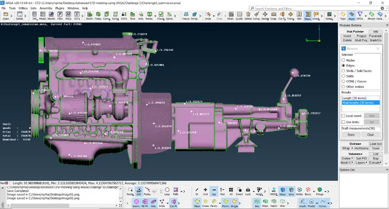
We can see that surface wrapping creates 7,66,878 mesh elements and also 15,542 surfaces are unmeshed as shown in the following figure.
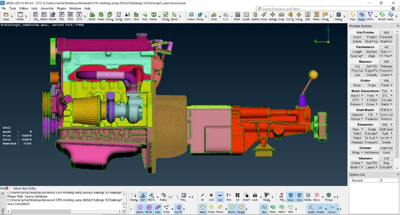
The unmeshed surfaces ae the interior surfaces of the merged file and are hence left unmeshed. We can see the meshed outer surface and the unmeshed internal surfaces in the following two figures.
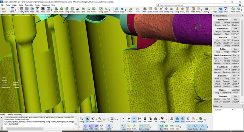
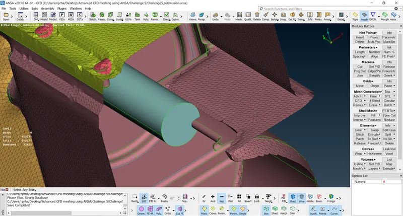
We can see that all the mesh elements created would be approximately 3mm in size across the entire geometry as shown.
Conclusion:
It is observed that the errors in the internal parts of the geometry don’t affect the final result of surface wrapping. Hence, we ignored the internal geometrical errors.
Surface wrapping is used in two conditions. When the internal structure for the given component is too complex. In this case, meshing the interior part would not be necessary if we want to study physics over the external surface. The second case is if we have lot of single cons and intersecting surfaces. Surface wrapping creates a water tight model very quickly and is hence preferred in lot of cases.
The geometry after performing surface wrapping is saved and can be accessed using the following google drive link.
https://drive.google.com/file/d/1vwdXCavm5slbny5cV_nPGdJsgDe5hXjj/view?usp=sharing
References: