Using Surface wrap meshing technique on Automotive Transmission assembly.
Objective:
Performing the surface wrap on Engine-Transmission-gearbox assembly.
Delete unnecessary faces, clean the surface geometry for errors and create a surface wrap that accurately captures geometry for accuracy to make subsequent simulation viable. The element's target length is 3mm.
The above-said goal is achieved by using the most widely used Pre-processing software named ANSA.
Surface wrap:
The surface wrap could be used to provide a closed, manifold, non-intersecting surface when starting from poor-quality CAD data. It is typically used when the imported surface includes problems such as:
- multiple, intersecting parts;
- missing data in the form of holes and gaps;
- surface mismatches;
- double and internal surfaces; and
- overly-complex geometry with too much detail;
The surface wrap could achieve many different aims simultaneously when applied. These include:
- Provide a closed, manifold, triangulated surface definition;
- close holes, gaps, and mismatches;
- "skin" double surfaces and remove internal features;
- simplify the surface geometry by removing unwanted detail;
- include baffle thickness inflation for desired internal features; and
- include refinements based on curvature, proximity, and/or individual surfaces
The resulting surface quality from the surface wrap is not optimal so it is usually used in conjunction with the surface mesh to provide a high-quality starting surface for the volume meshes.
Steps involved in geometry clean-up by ANSA:
1. The solid part is imported into ANSA GUI. Select File-->Open and select the required solid geometry for import from the directory path.
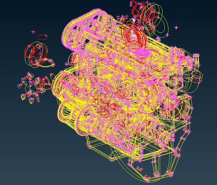
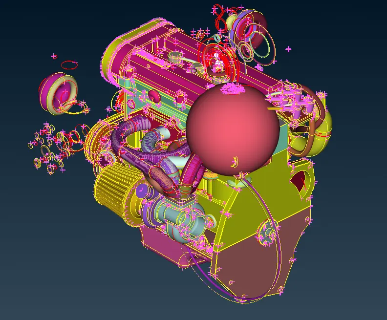
2. The solid part is initially imported as a wireframe model in ANSA and it is changed into a solid model by clicking on the shadow icon .
.
| Wireframe | Solid |
 |
 |
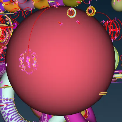
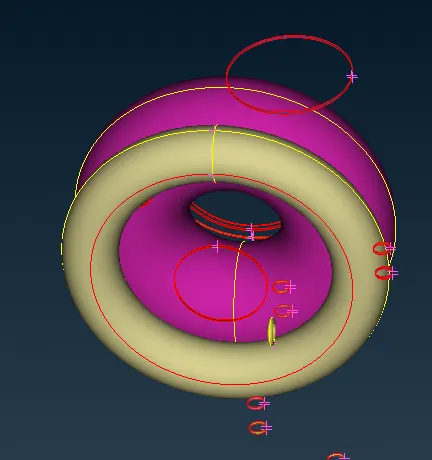
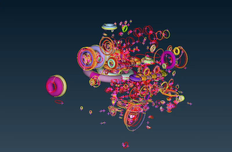
3. In the below figure clear recognization can be made that the Donut, Spherical, and ring-shaped surfaces present are not part of engine assembly, these were used by designers to make fillet and curvature shapes. These would not become part of the surface wrap.
| Sphere | Donut and Rings |
 |
 |
4. Delete these surface chunks present outside by box select and universal delete. Validation should be done before deleting any surface so that necessary and complex engine geometries are not to be deleted. Rotate the geometry and use zoom-in/out for visual inspection.
 |
| Hidden Major components by NOT button. |
5. Hide major engine components using the PID mode NOT command to easily delete dispensable parts.
6. Activate the  “Lock” flag button in the Focus Toolbar to lock the currently visible entities. Now when you press the “All” button, only the selected and locked entities will become visible.
7. Press  select necessary surfaces using the left mouse button and then press the middle mouse button after close inspection for confirmation. Selected parts will be deleted.
8. In this project only geometry errors of outer surfaces would be cleared because surface wrap mesh happens only for outer surfaces.
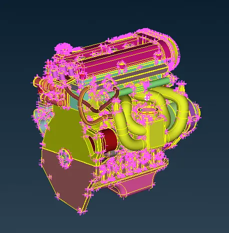
Reconfigured Geometry
9. It is needed to clear red cons and blue cons which would be directly influenced by surface wrap mesh. Those which were visible and present outside.
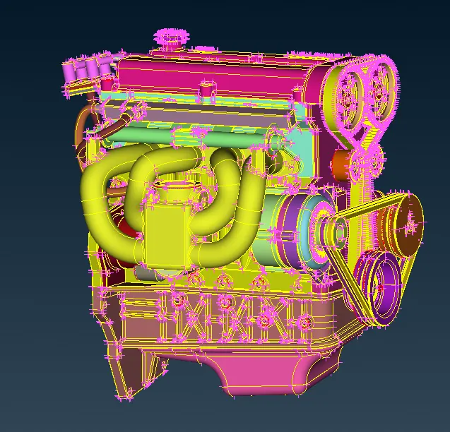
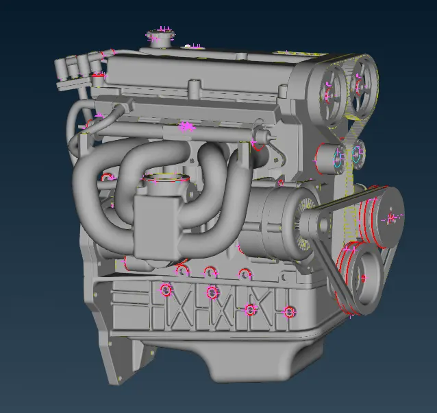
10. Disable yellow cons in the Face Draw menu by clicking on the Double  icon. then change the view from PID to Entity mode. By performing this operation red cons and blue cons would be associated effortlessly.
| Double CONS PID mode | Disabled Double CONS in PID mode. |
 |
 |
11. Repair all visible red cons gradually.
12. Starting with the Oil chamber casing part/base part. The steps are manifested below.
| i. Red cons was identified at outside parts of the oil chamber. | 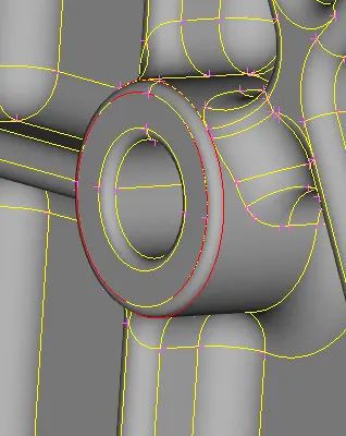 |
ii. Use Topo command  red cons would be transmuted to blue cons. red cons would be transmuted to blue cons. |
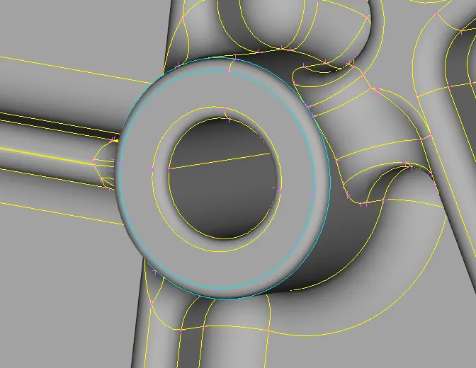 |
| iii. Hide the top surface and delete the inside surface. | 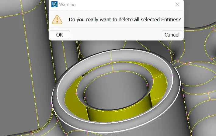 |
| iv. Done, red cons were wholly repaired. Delete wherever necessary and all surface errors were resolved similarly. Using this method eliminates all errors which are present in the file. Do it wherever errors are present but only on the outer side. | 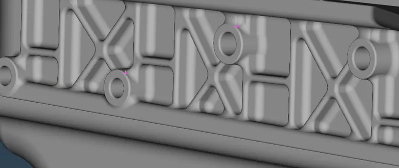 |
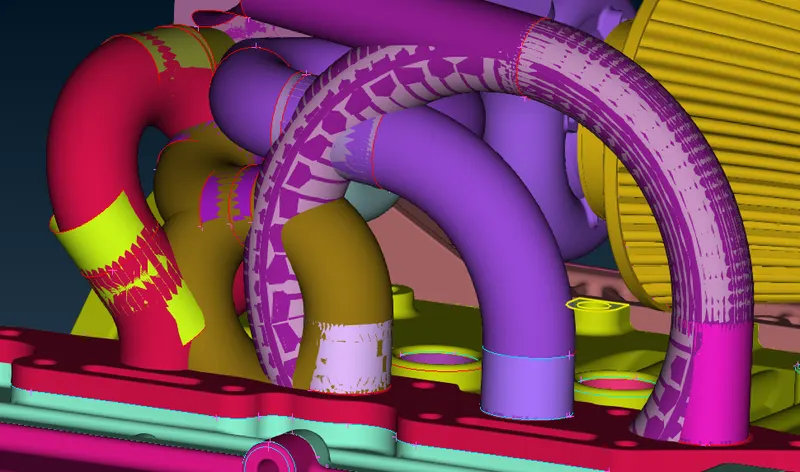
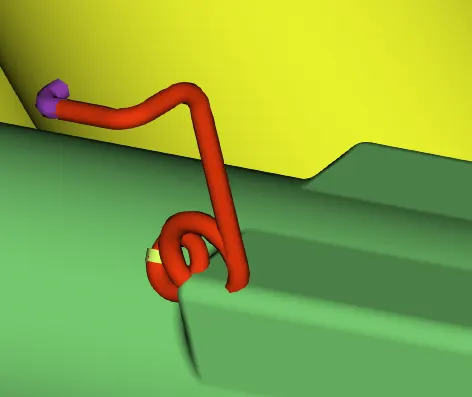
13. In the visible figure below, these tubes intersect with each other. Eradicate these all. The surface wrap would not apply efficiently on this kind of curvature surface.
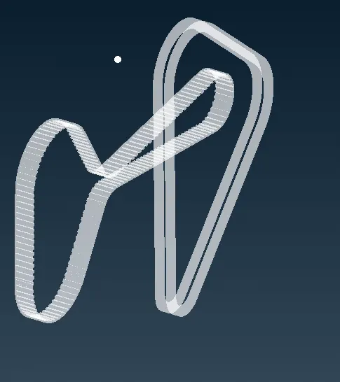
14. Delete belts due to small curvatures and edge lengths, which would stipulate more amount of cells with small sizes to capture details.
15. Before performing surface wrap we close all the open surfaces in the model because when we apply the wrap on the model before closing the open surfaces it will create skewness on the model so we do first close all the open surfaces.
16. All single cons visible from the outside are eliminated
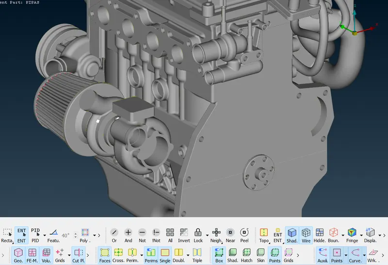
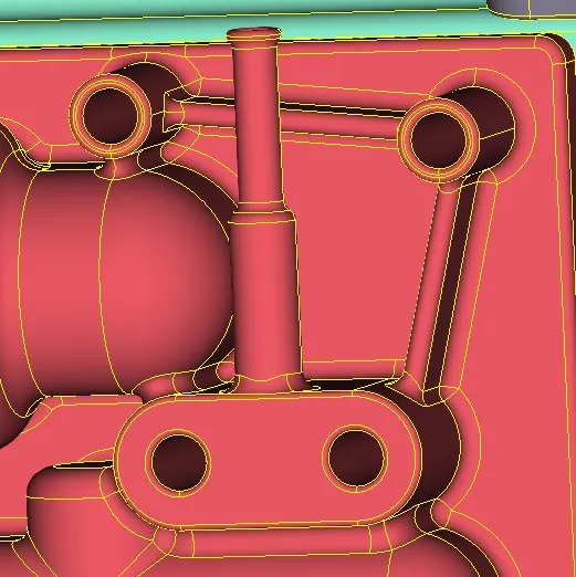
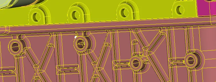
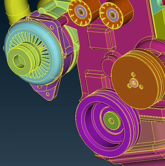
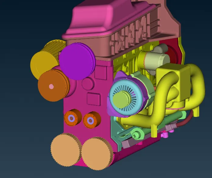
17. To close the open holes we use the fill hole option to completely close all the open holes. The model after closing all the open holes is shown below.
18. To view the complete Faces that were left visible, activate the DOUBLE CONS button. Activate also the “Cross Hatches” button. This allows the visualization of two green dashed lines along the center isoparametric of the Faces.
-----------------------------------------------------------------------------------------------------------------------
TRANSMISSION
Transmission is having very less errors. Delete an extra surface which is present beneath surface and repair bolts triple cones.
| 1. Hide the outer cover are using not option. | 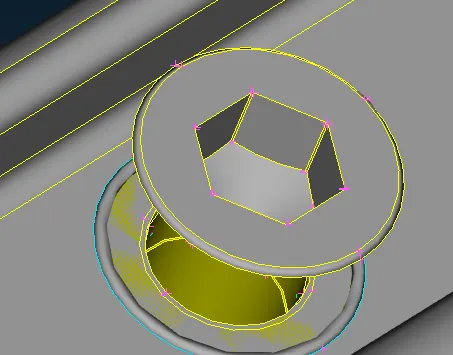 |
| 2. Delete the ringed surface present. Go for a TOPO, do this procedure for triple cons present near screw. | 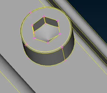 |
| 3. Delete donut shaped structures which are the source of triple cons. | 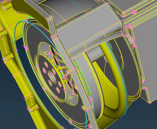 |
| 4. Delete unnecessary sharp surfaces. | 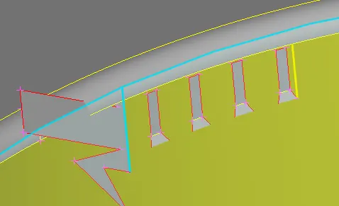 |
| 5. Delete open curves. | 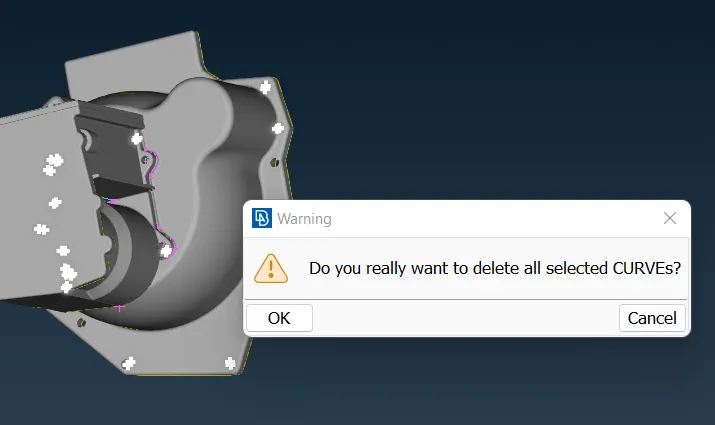 |
| 6. Delete internal cylindrical shaped surface as this will not be included in surface wrap. | 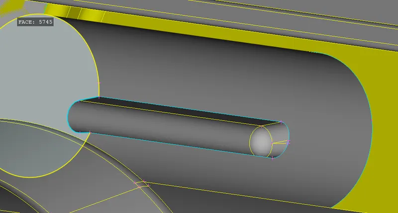 |
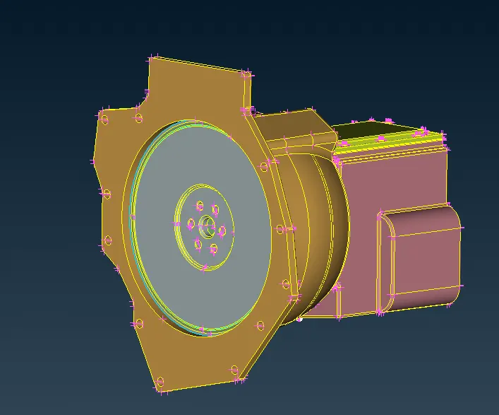
Transmission preprocessing completed. Next for gearbox.
-----------------------------------------------------------------------------------------------------------------------
GEARBOX
| 1. Delete the triple cone triangular surface. Use CUT surface option, form a new surface coons. | 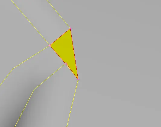 |
|
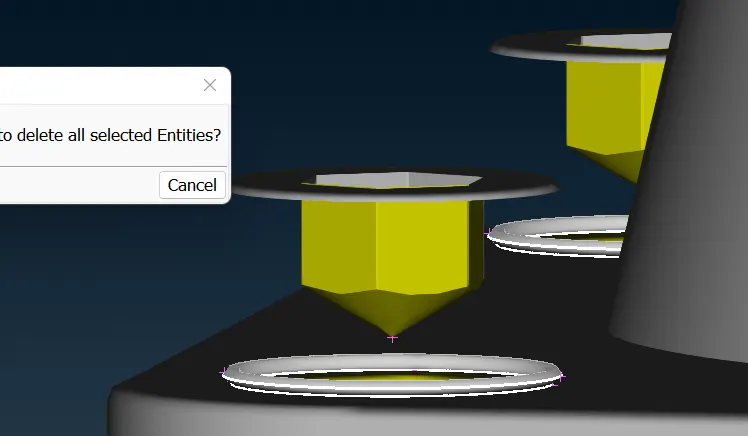
2. Delete triple cons structure at bolts. Hide using NOT---> Select surfaces---> Universal Delete. |
 |
| 3. Delete ringed structure causing triple cons and delete double surfaces hidden beneath gear lever. | 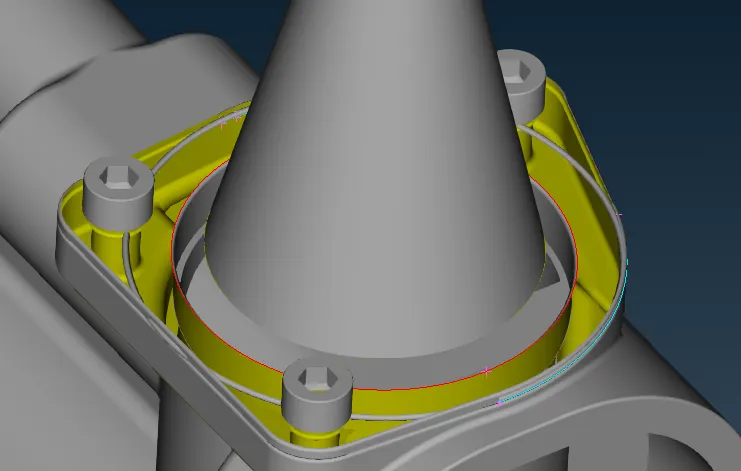 |
| 4. Delete face generating red cons. Remake a surface using new--> faces--> Coons. | 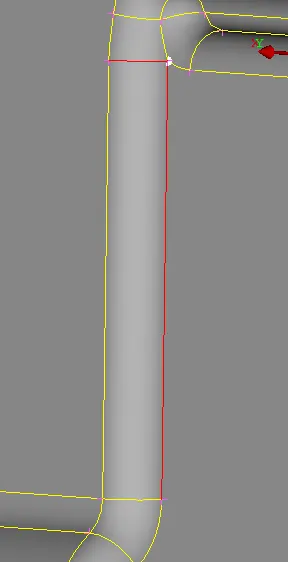 |
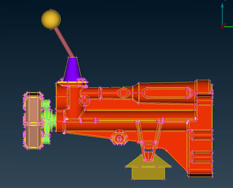
All subassemblies post processing completed up until this point. Assembly for Engine-Transmission-Gearbox would be the next operation.
-----------------------------------------------------------------------------------------------------------------------
ASSEMBLY
ANSA has an invaluable assembly feature. To join parts and components methodically, use the merge solution.
Energy flows first from the engine towards the transmission system (flywheel to geartrain), which is controlled by the gearbox, in the power transmission system. As a result, the transmission system comes first in assembly.
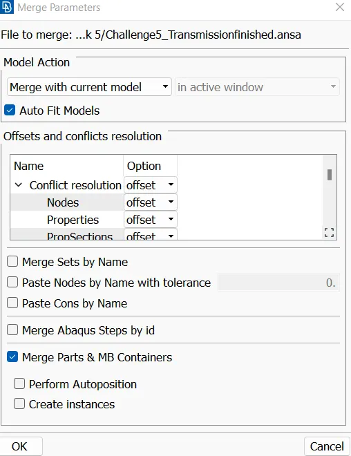
Under file select Merge option for assembly of transmission. By selection Merge a dialox box would open named merge parameters. Use Merge with current option as shown below.
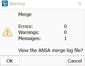
ANSA will dislpay a warining box as shown below. File should be imported without errors.
Similarly import gearbox file in ANSA.
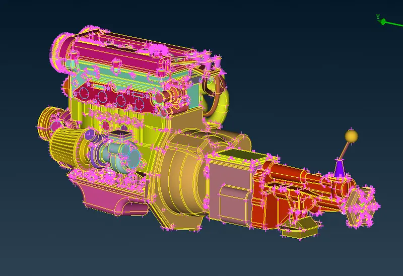
After assembly check for open edges and use fill-hole option to close all open holes and surfaces present.
-----------------------------------------------------------------------------------------------------------------------
MESHING (SURFACE WRAP)
1. Before going for surface wrap use compress  option for deleting inessential PIDs.
2. Use WRAP option under ELEMENT with constant length in MESH mode. There are two options in Wrap namely Wrap with constant length and varrying length. Constant length is used in our case to have constant length wrap in all the surfaces.
3. A target element length of 3mm and smooth factor of 0.5 was used.
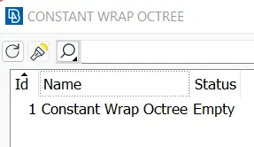
4. Press Click on constant length wrap. Constant Wrap Octree dialox box would open. Double click on 'Constant Wrap Octree'. Renamed parameters as Wrap.
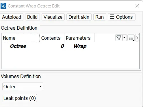
5. Click on Parameters--> Wrap. Constant Wrap Octree: Parameters dialog box would open. Give target length as 3mm.
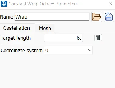
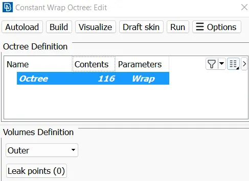
6. In Constant Wrap Octree: Edit dialog box it is evident that PIDs should be added to apply surface wrap. Addition of surfaces takes place manually in ANSA thus double click on Contents.
7. Contents of Octree Scenerio dialog box will open up. Select all PIDs visible on Left Hand Side, then click on green arrow button. All PIDs would be transferred to right hand side box.
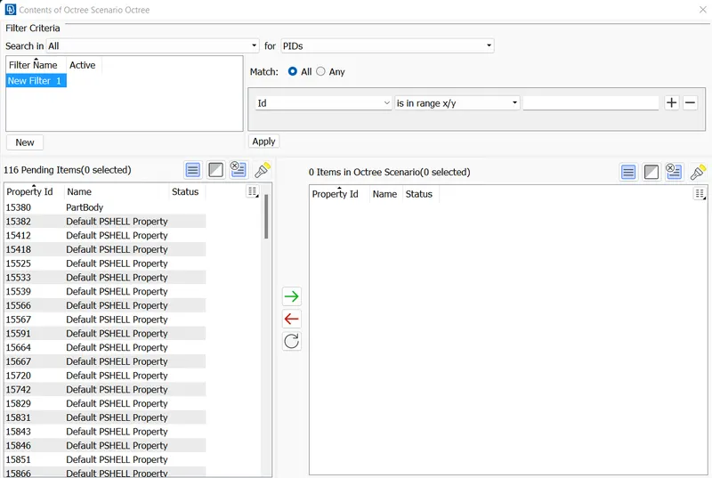
8. Under edit dialox box 116 PIDs were present. All checks were very well observed surface wrap was applied by designating 'Run' couse of action.
9. Surface wrap was completed on assembly with 155932 total tria elements.
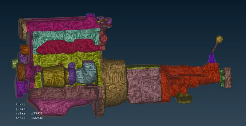
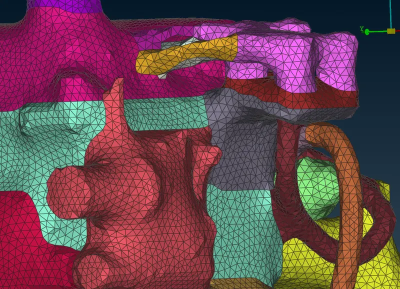
10. Mesh wrap has reasonably captured surface details such as pipe, hoses, shaft and gear lever.
-----------------------------------------------------------------------------------------------------------------------
Conclusion :
- The given three individual models were cleaned for different types of surface errors using set of tools available in ANSA.
- The three models were merged using Merge to create a common volume.
- The three models were Surface Wrapped for the given target length and surface smooth values.
- New commands learned: Elements->Wrap and Compress PID
 .
.
ANSA file link: https://drive.google.com/file/d/1isSsKkNtszppjnkSty2MfMtbt5ngI3Tt/view?usp=sharing