Week 5 Challenge : Surface wrap on Automotive Assembly
AIM :
To perform the surface wrap on the assembly model that consists of the given engine, gearbox and transmission models which are merged together.
OBJECTIVE :
- To check for any geometric errors in the external surfaces of the given engine, gearbox and transmission model and to do the topological clean up in it by deleting all the unwanted surfaces for performing the surface wrap.
- To merge the given engine, gear box and transmission models into a single assembly model.
- To close all the external openings in the model by creating the surfaces on it.
- To perform the surface wrap on the model with the mesh target length as 3mm.
Tools used :
MENUBAR>Drawing Styles>Shadow - This flag turns on and off the shadow drawing style.
MENUBAR>Drawing Styles>Wire - This flag activates the wire model representation of the geometry and the FE-Model.
MENUBAR>Faces Draw>Cross Hatches - This flag activates and deactivates the visibility of Faces' cross-hatches. As this flag is activated, green isoparametric lines that lie on the visible Faces appear. If the Faces are linked Faces the color of the crosshatch is orange.
MENUBAR>Faces Draw>Single - This flag activates and deactivates the visibility of single (red) CONS.
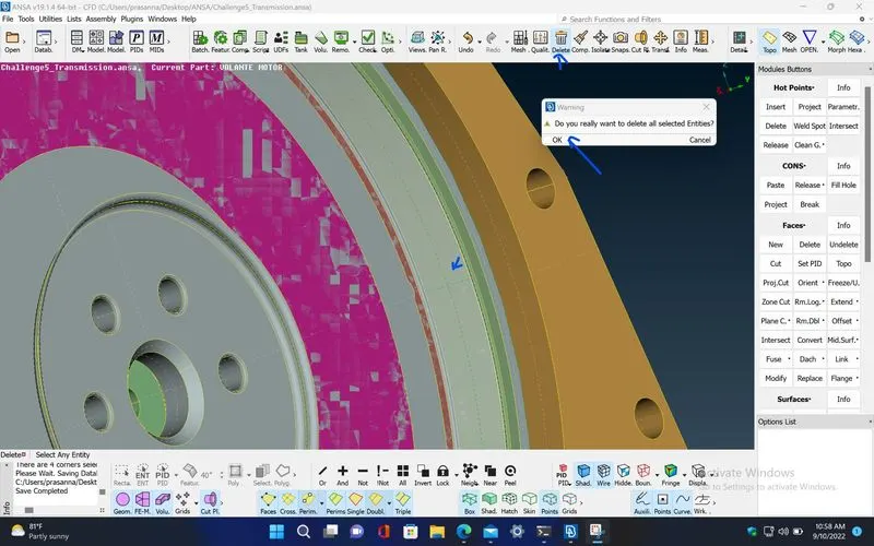
MENUBAR>Utilities>Delete - The Delete function of the Geometry Group can be used to delete various ANSA entities (Curves, Faces, FE-Model entities etc.).
TOPO>CONS>Project - This function projects, as CONS or 3D Curves, a number of selected 3D-curves, CONS, element edges, line elements or Hexa Box edges on a number of selected Faces, in a user controlled direction. The selection of the CONS or 3D-curves can be assisted by the 'Corner Angle', 'PID Neighbs' for line elements or 'Path'.
TOPO>Hot Points>Insert - This function creates or projects Hot Points by hovering positions on CONS or 3d curves or 1d FE elements.
TOPO>CONS>Fill Hole - This function fills holes on Faces. The holes can be of any shape. Such internal openings can be selected individually, or automatically among the visible ones if they fall below a user specified diameter value. There is the option to create automatically 3D Curves, Points or Connection Points of the removed holes, in order to mark their shape and position for reference.
TOPO>Hot Points>Project - This function defines a new Hot Point that lies on a CONS (or a Node on a 3D-curve) as the projection of an existing Node, 3D-point, Hot Point, Weld Spot etc.
This function also defines a new Weld Spot that lies on a face as the projection of an existing node, 3D-point etc. to this face.
TOPO>CONS>Release - This function releases CONS which have been automatically joined (pasted) or were joined by the CONS>Paste function.
TOPO>Hot Points>Release - This function releases Hot Points that lie on the limit of two or more faces. When a Hot Point is released, the adjacent CONS of the faces' limits are also released and become single CONS (marked in red). As a result, the local topology changes
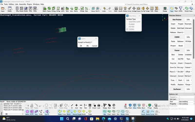
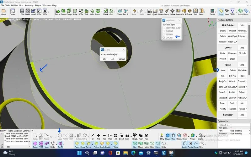
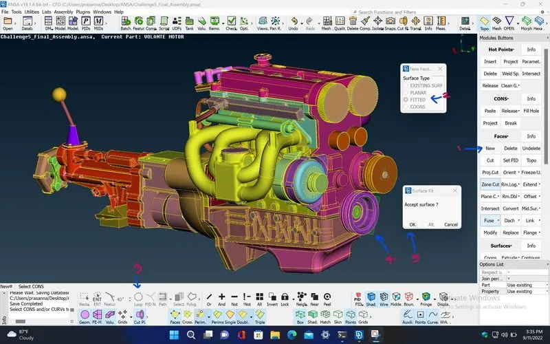
TOPO>Faces>New - This function defines a new surface by selecting its boundary curves and creates a corresponding face that covers the new surface. The calculated surface appears as a net.
New [COONS] -
This function defines a new multi-patch Face and Surface, using the COONS interpolation principal. This is an easy way to define a new surface by its boundary curves. After the mathematical definition is finished, the calculated surface appears as a net. A relative window gives the ability to accept or to reject the calculated surface. When only three boundary sides are selected, there is the ability to choose between two alternative definitions for the fourth generated side, one is to be straight and the other is to have a shape similar to its opposite side.
New [EXISTING SURF] -
This function defines a new Face laying on an existing surface.
New [PLANAR] -
This function defines a new planar face. The underlying surface is automatically created.
New [FITTED] -
The FITTED option is used for the definition of a non-planar Face. The created Face fits to the selected boundaries.
TOPO>Faces>Cut - This function cuts (splits) an existing Face or joins faces if inverse operation is applied (right mouse button).
It does not require the existence of Hot Points since it can be applied directly on an arbitrary position of a CONS.
TOPO>Faces>Proj.Cut - This function is used to cut (split) a Face by combining the Hot Points>Project and Faces>Cut functions. In other words, it splits a face between a selected hot point and its projection on a selected CONS.
MENUBAR>Feature Selection>Line Options>Loop - Selects a closed loop of edges, perimeters or curves. Any internal or external perimeter is considered a loop.
MENUBAR>Feature Selection>ENT - Selects any kind of entity (the kind of entity depends on the ANSA function which is in use) one by one or multiple entities by box selection.
MENUBAR>Feature Selection>Surface Options>PID Region - If the 'PID Region' flag is activated, then by picking an element (shell or solid) of a particular PID, ANSA automatically selects all the connected visible elements, which are assigned with the particular PID.
MENUBAR>Feature Selection>Surface Options>PID - Selects properties either one by one with the left-mouse button or multiple properties by box selection.
MENUBAR>Focus>Or - Keep visible only the selected entities.
MENUBAR>Focus>And - Select one or more already visible entities, in order to also bring to visible any neighbor entities which may exist.
MENUBAR>Focus>Not - Hide one or more selected entities.
MENUBAR>Focus>!Not - Select entities that will remain visible. The selected entities temporarily (during selection) are excluded from the visible ones, but as soon as 'Enter' or the middle mouse is pressed (selections' termination) then they will only be the ones to remain visible in the graphics area.
MENUBAR>Focus>Invert - Inverts the current visibility status. This means that visible entities become non-visible and non-visible entities become visible. If one or more Parts are Locked then this function operates exclusively in the Locked Parts.
MENUBAR>Focus>All - Bring to visible all entities of the database. If the Lock flag button is active, then the function brings to visible only the entities that belong to the active locked view.
If there are numerous stored locked views, then they will be displayed as a sub-options list of the All button.
MENUBAR>Focus>Lock - This function locks the current working area view. This working area view is kept locked until the flag is turned off. There is also the ability to store different kinds of views of the same model. The status and the content of the working area influence the result of the All function.
MENUBAR>Focus>Neighb - Logical operation that brings to visible all the 1st level neighboring items attached to the already visible ones.
TOPO>Faces>Topo - This function automatically creates topological conditions between selected adjacent CONS.
TOPO>Faces>Extend - This function extends Faces (source), according to a specified distance or until they reach a target Face or target group of Faces, by adding new Faces as extensions to the source ones. The new Faces' Surfaces are extensions of the Surfaces of the sources. Topology can be applied automatically, if required.
TOPO>Faces>Orient - This function sets a uniform orientation direction to all visible Faces according to the orientation of the majority of the Faces. The mesh elements that will be generated, or those already existing, also obtain a uniform orientation.
TOPO>CONS>Paste - This function pastes (joins together) two or more CONS segments that lie close to each other, and which usually are boundaries of different Faces. A new topological condition is created and these Faces become neighboring.
TOPO>Faces>Undelete - This function recovers a Face that was previously deleted, provided that the COMPRESS command was not used since the Face was deleted. As the Faces>Undelete function is activated, all deleted Faces still in the database become highlighted and can be selected for recovery.
TOPO>Faces>Intersect - This function defines the intersection between two groups of Faces and/or FE elements that penetrate each other. Topology can be applied automatically if required. In case that the two groups can define a closed volume between them, Boolean operations can be applied.
TOPO>Hot Points>Delete - This function deletes Hot Points lying on a CONS segment. After deletion, the adjacent CONS segments sharing the Hot Point become one.
MENUBAR>Lists>Properties - This function facilitates property management. A list of the properties existing in the file is available. Management windows, such as this one, provide filtering, sorting and selection capabilities on the listed entities as well as definition of new entities.
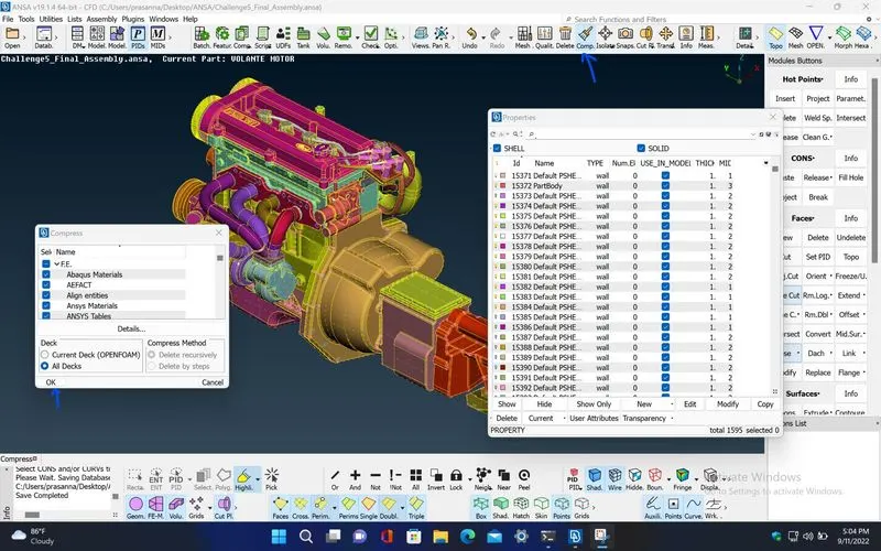
MENUBAR>Utilities>Compress - This function is used to compress an ANSA database. Compression may be selectively applied either on geometric entities only (faces, curves 3D-points) or on the entire database. By this operation, all information concerning deleted entities is lost. Therefore no undelete operation can be made upon entities which were deleted prior to the compress operation. This function relieves the database from unwanted information. Also, this function removes from the database all grid points, coordinate systems, properties and materials that are defined but not used in the model element definition.
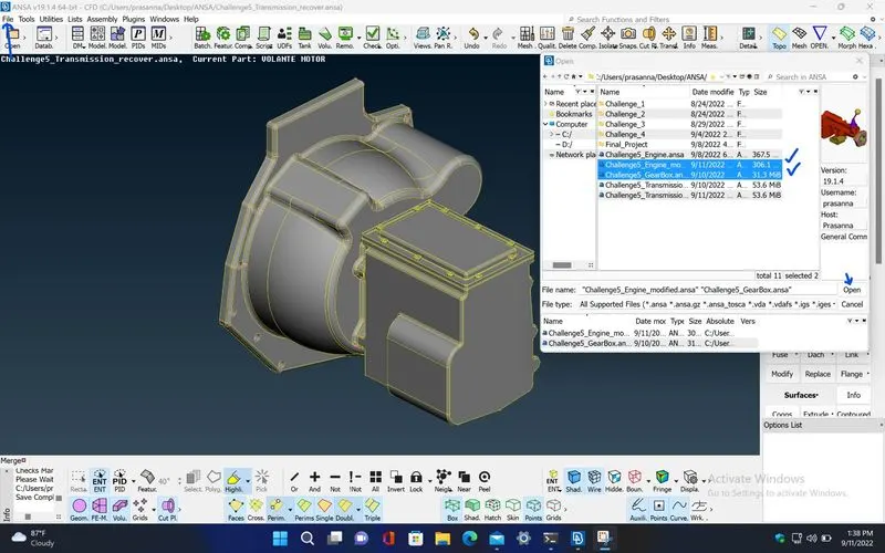
MENUBAR>File>Merge - This function activates the file manager in order to merge ANSA files or neutral format files to the currently loaded file in ANSA.
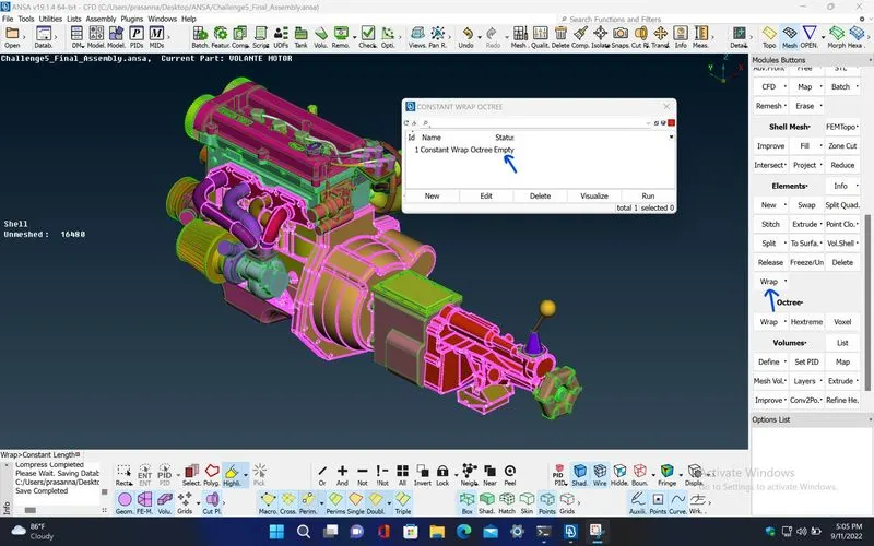
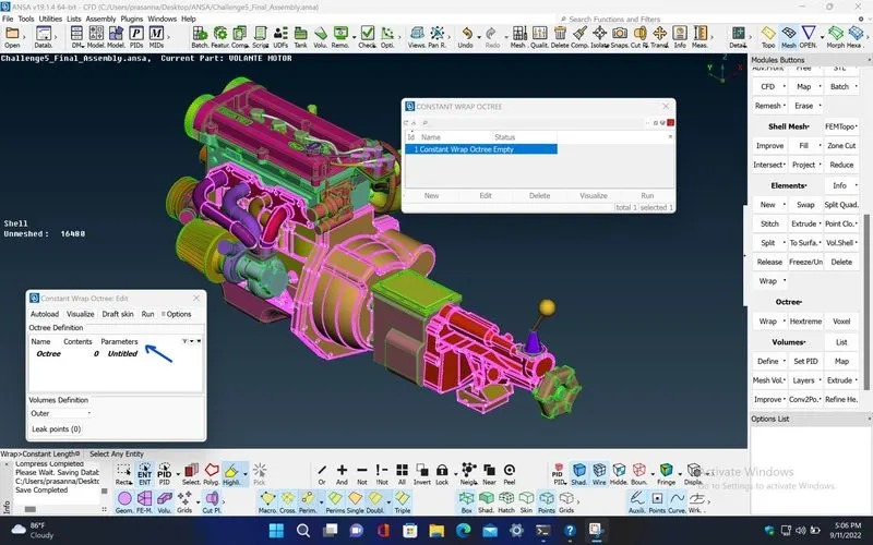
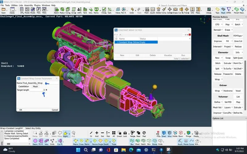
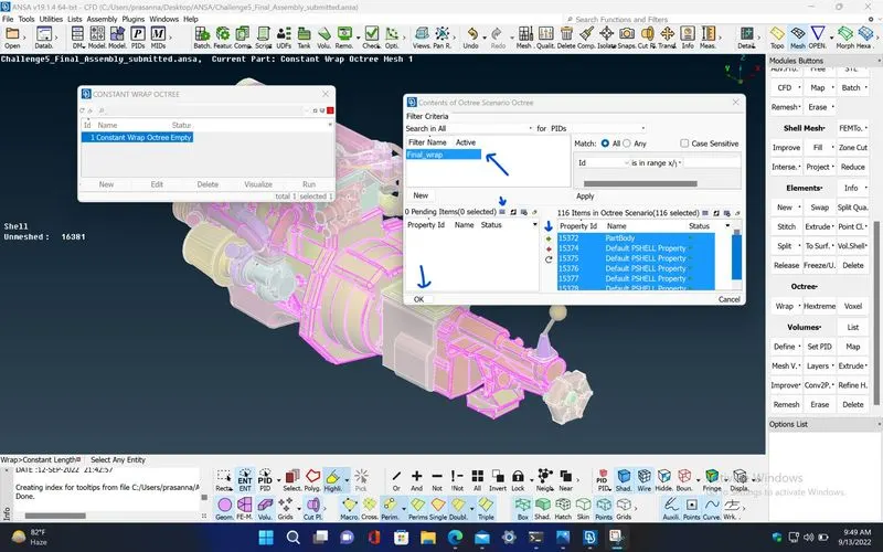
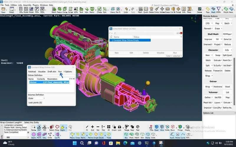
MESH>Elements>Wrap [Constant Length] - Constant Length Wrap is a very fast algorithm that can create a watertight triangular surface mesh of uniform size from an assembly of unconnected and intersecting components. It can be used for various analyses like CFD, NVH and more.
MENUBAR>Visibility>FE-Mode - This flag activates and deactivates the visibility of FE-Model items that are not defined by the structure's surface geometry. Such items could have been defined in any DECK menu, or might have been imported by the FILE>INPUT function.
MENUBAR>Visibility>Geometry - This flag activates and deactivates the visibility of geometric entities (3D-points, 3D-curves, Faces etc.)
MENUBAR>Utilities>Measure - This function performs various measurements according to the corresponding Selection Mode. The applied measurements can be saved and viewed at a later stage.
MENUBAR>Utilities>Snapshot - Take snapshots from the drawing area or from any ANSA window. Depending on the selected option the image can be: POSTSCRIPT, RGB, TIFF, JPEG, PNG or BMP.
PROCEDURE :
STEP 1 : First, open the given engine model into the ANSA by using MENUBAR>File>Open
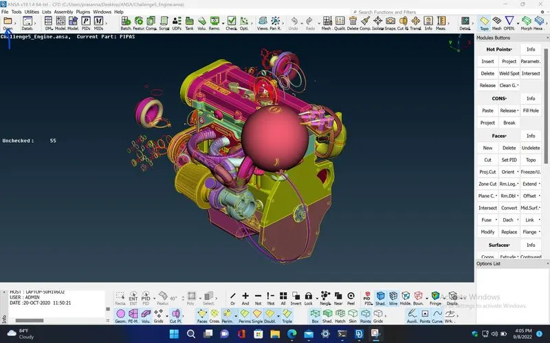
STEP 2 : To show only the unchecked surfaces in the given model, right click on the term 'Unchecked' and click on 'show only' . Now, Delete the unchecked surfaces using MENUBAR>Utilities>Delete
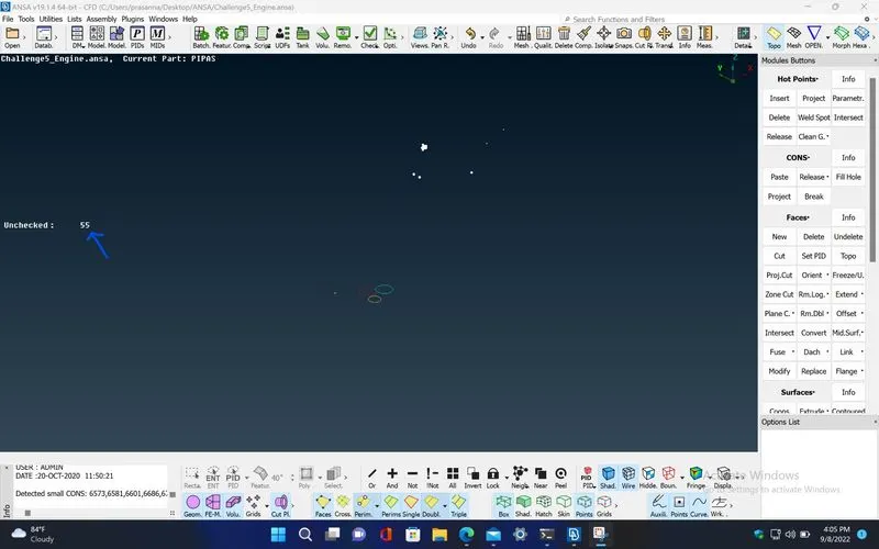
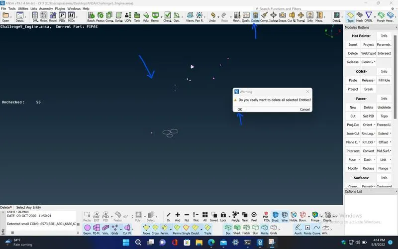
STEP 3 : Delete all the unwanted surfaces present outside of the given engine model. Use different views of the model for selecting and deleting the unwanted surfaces easily.
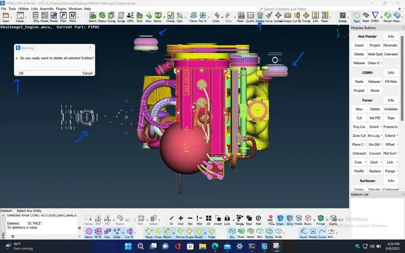
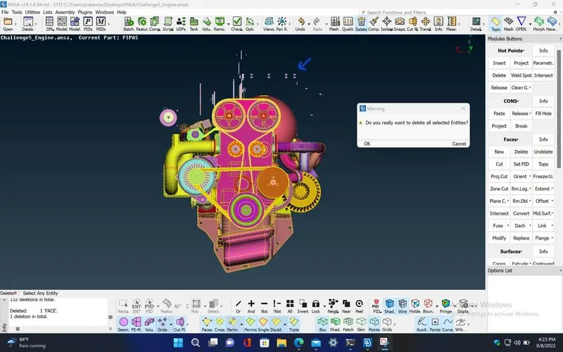
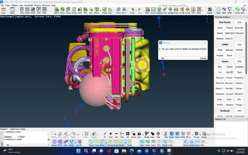
STEP 4 : Now, Hide all the surfaces in the given engine model which are needed for the surface wrap using MENUBAR>Focus>Not and use MENUBAR>Feature Selection>Surface Options>PID Region for selecting the particular PID regions.
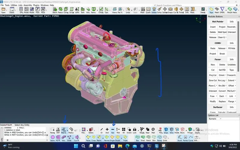
STEP 5 : Delete all the unwanted surfaces which are mostly torus shaped surfaces.
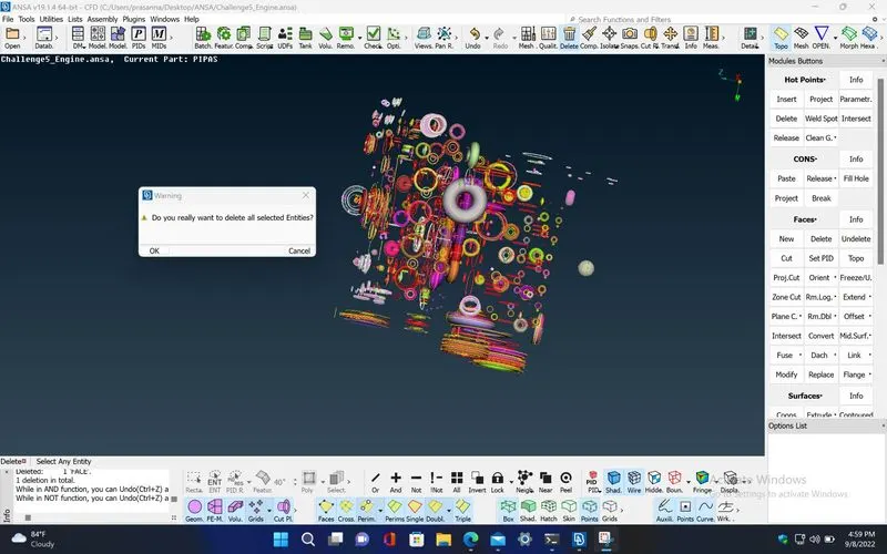
STEP 6 : Mostly, Delete all the unwanted (overlapping) external surfaces since the surface wrap is performed only on the external surface of the model.
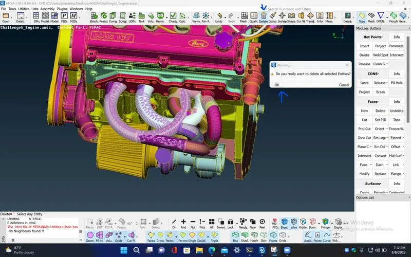
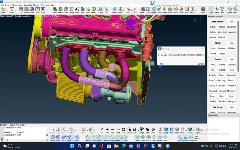
STEP 7 : Delete the belts in the given engine model since its thickness is very small, it can't be surface wrapped properly. Also, delete the overlapping surfaces present in the external region of the model.
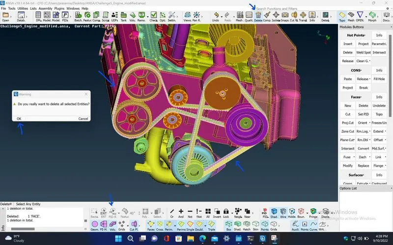
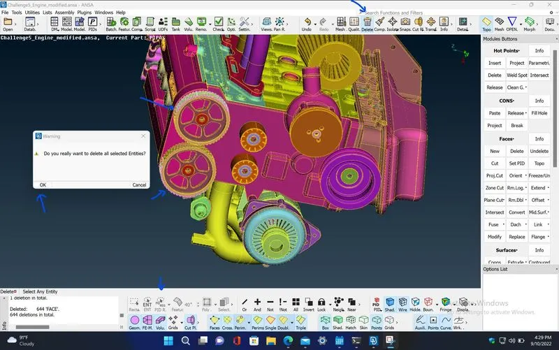
STEP 8 : After finishing the required topological clean up in the engine model, close the engine model. Now, open the given transmission model by using MENUBAR>File>Open
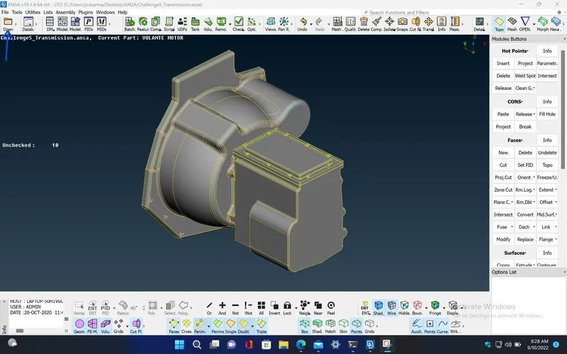
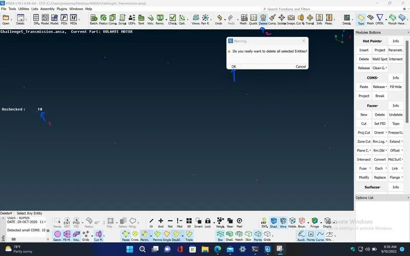
STEP 9 : Delete all the unchecked surfaces by repeating the same procedure done on the engine model.
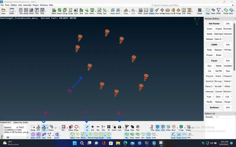
STEP 10 : Isolate the bolt shaped PID, using MENUBAR>Focus>Or, and MENUBAR>Feature Selection>Surface Options>PID for selectng the PID.
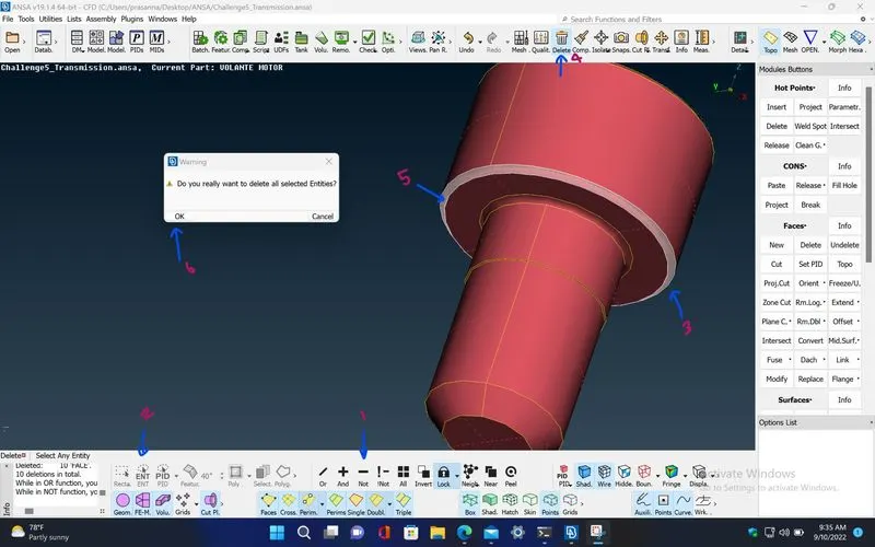
STEP 11 : Delete the unwanted overlapping surfaces that produces triple cons.
STEP 12 : Now, Hide all the surfaces in the given transmission model which are needed for the surface wrap using MENUBAR>Focus>Not and use MENUBAR>Feature Selection>Surface Options>PID Region for selecting the particular PID regions.
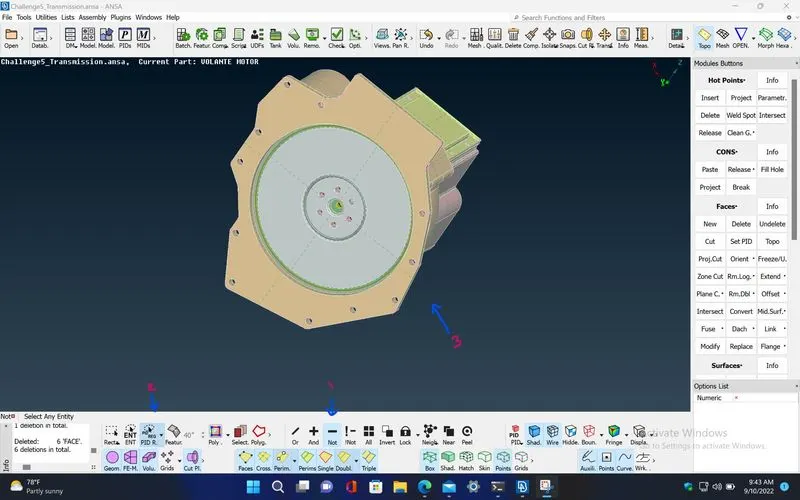
STEP 13 : Delete all the unwanted surfaces which are mostly torus shaped surfaces.
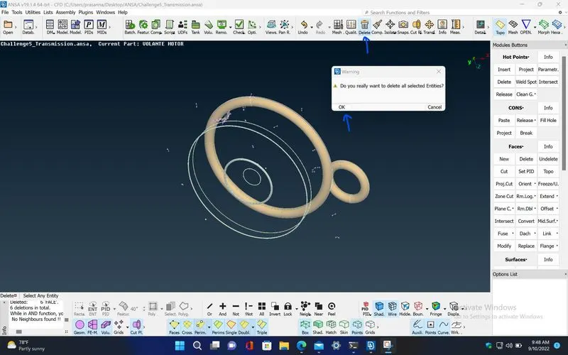
STEP 14 : Delete the unwanted overlapping surfaces present in the external regions of the transmission model.
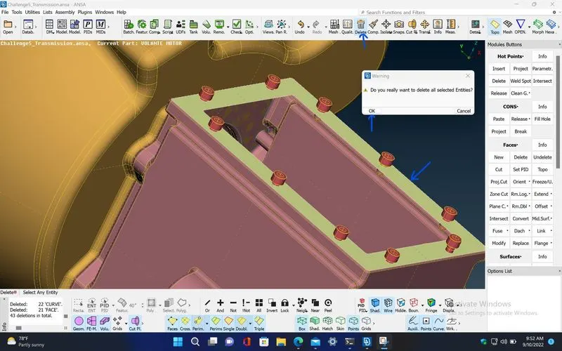
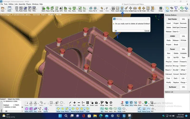
STEP 15 : Create new surfaces using TOPO>Faces>New where there are single cons present due to missing surfaces.
STEP 16 : After finishing the required topological clean up in the transmission model, close the transmission model. Now, open the given gear box model by using MENUBAR>File>Open
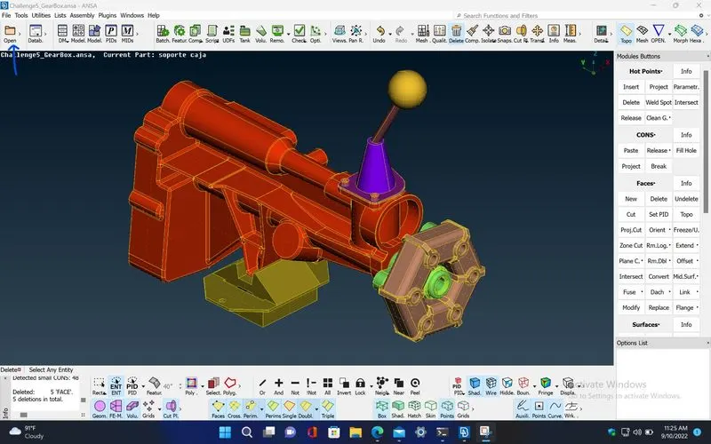
STEP 17 : Now, Hide all the surfaces in the given gear box model which are needed for the surface wrap using MENUBAR>Focus>Not and use MENUBAR>Feature Selection>Surface Options>PID Region for selecting the particular PID regions.
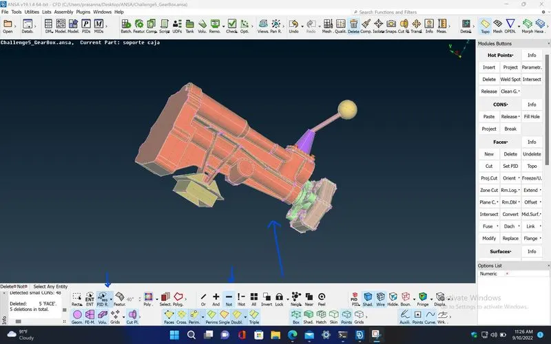
STEP 18 : Delete the unwanted surfaces as did before.
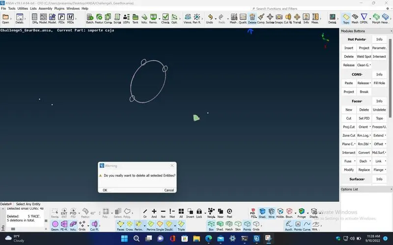
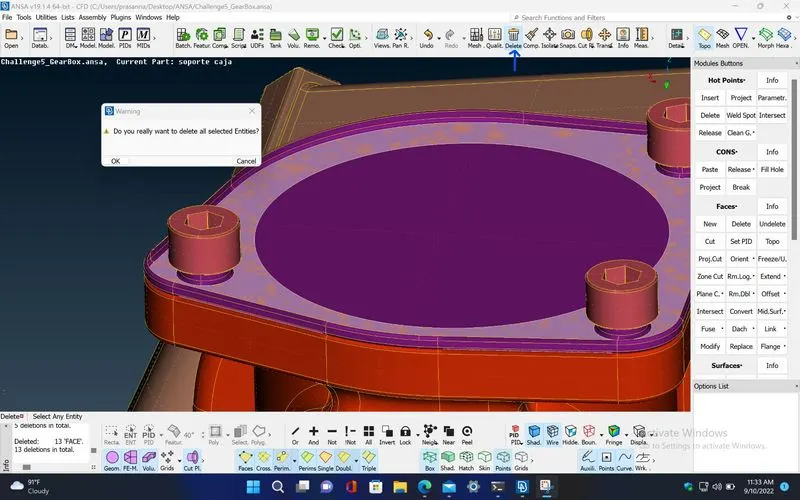
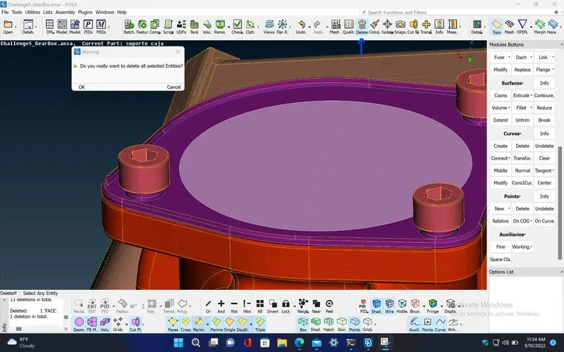
STEP 19 : Create new surfaces using TOPO>Faces>New, wherever required.
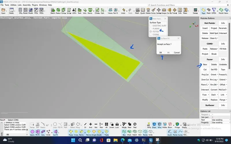
STEP 20 : Now, After finishing the required topological clean up in all the gear box model, merge the other two models (engine and transmission) into the current model (gearbox) using MENUBAR>File>Merge
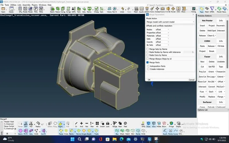
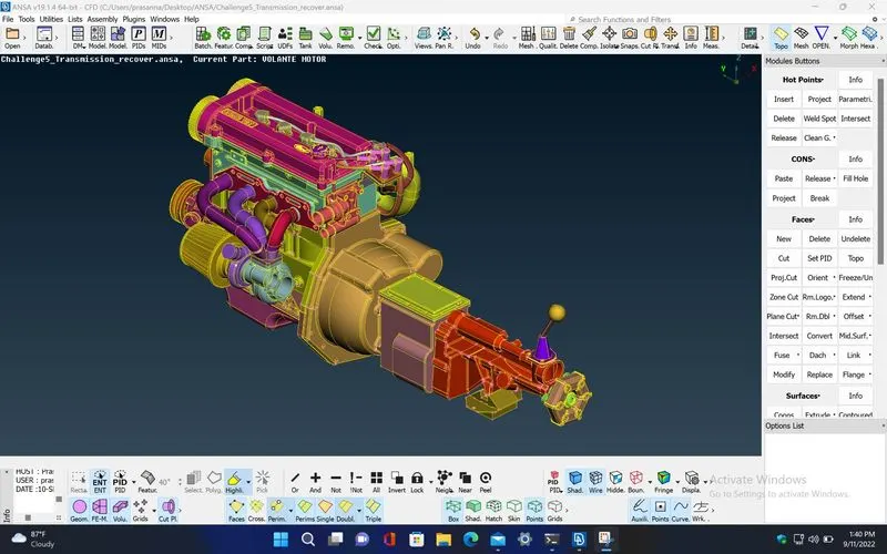
STEP 21 : After merging all the three models, create new surfaces to close all the openings present in the external regions of the model for performing surface wrap. Usually, surface wrap can't capture the geometry properly when there is a opening in the external region of the model.
STEP 22 : Use MENUBAR>Utilities>Compress for forcefully deleting the unwanted PIDs which are got already deleted.
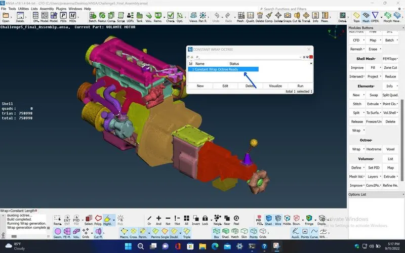
STEP 23 : Now, perform the surface wrap using MESH>Elements>Wrap [Constant Length] with constant mesh target length of '3 mm' for the final model.
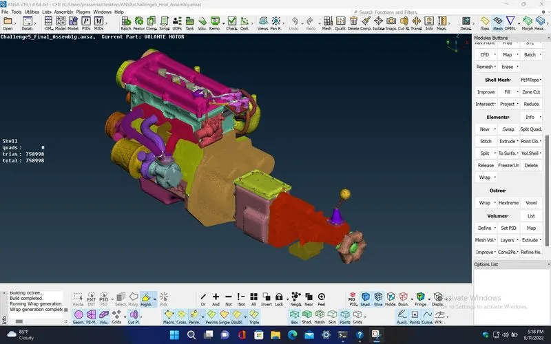
STEP 24 : After performing the surface wrap on the model, check if there is only a single internal volume present. To do that, first deselect the geometry visibility from MENUBAR>Visibility>Geometry and select the FE visibility from MENUBAR>Visibility>FE-Mode. Then, hide the front and rear end surfaces as shown below using 'Not' option.
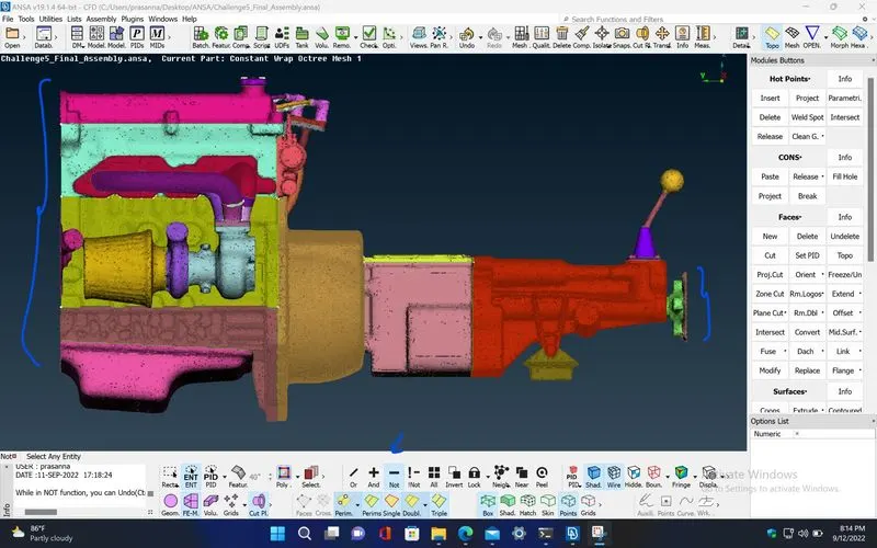
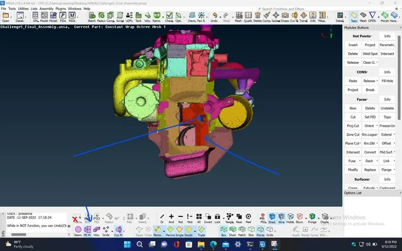
STEP 25 : Now, check the internal volume of the surface wrap.
RESULTS :
Google drive link for the final assembly model with surface wrap :
https://drive.google.com/file/d/1pymvh9RNZRYlgMAObqyrTFyTWgbDZE07/view?usp=sharing
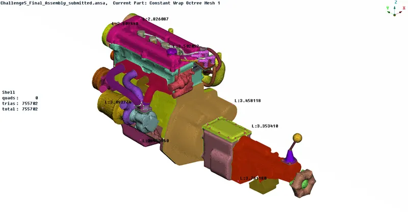
Final screenshot of the final assembly model with surface wrap :
CONCLUSION :
The total mesh elements(trias) in the final assembly model after performing the surface wrap is 755702, which indicates the elements present only in the wrap (i.e, in the external surface of the assembly model). This gives a single internal volume for the final assembly model which can be used for flow analysis over the external surface by performing the volumetric mesh which can be done by enclosing the assembly model by the fluid domain. Therefore, performing surface wrap takes only less computational time compared to the surface meshing, for which we need to do all the geometric clean up for the entire model (in both internal and external surfaces). But, in contrast, the surface wrap won't provide more accurate results compared to surface meshing.