Week 5 Bending of iPhone
1. Objective
We have to simulate the bending of the iPhone for 2 cases
Case 1: Simulate as per the video
Case 2: Open space claim and move the 2 bottom fingers to a new position defined by X=22.5mm and Z=10mm and then obtain simulation results. Also based on the values of stress and number of cycles, we have to define the S-N curve for Aluminum alloy material and then find the fatigue results for the same.
Then we need to find the directional deformation for the model, a factor of Aluminum alloy NL, Life of aluminum alloy and then compare these results.
2. Case setup and execution
Case 1
In engineering, data add new materials such as Aluminum alloy NL, Glass and Polyethylene
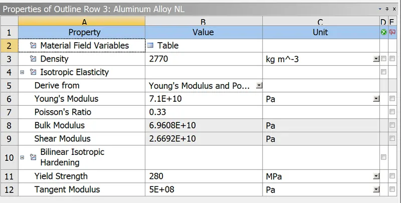
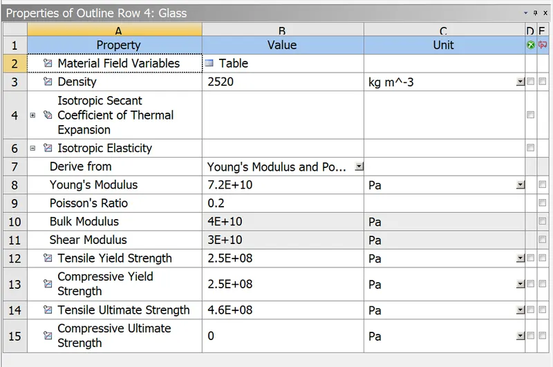
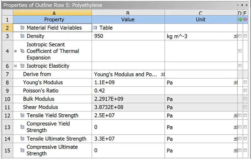
Import geometry file. Using the repair feature, reduce the number of faces on fingers in SpaceClaim.
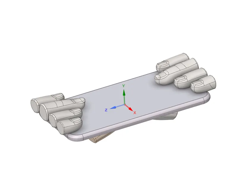 Then update the model to include upstream data.
Rename the geometry items.
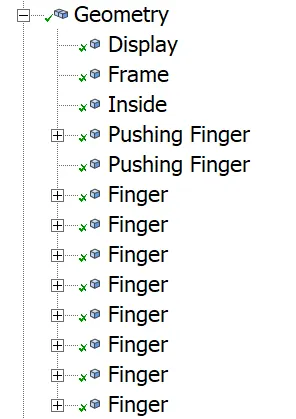
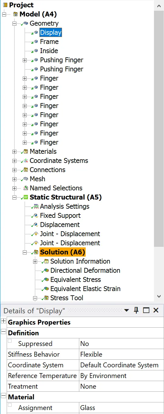
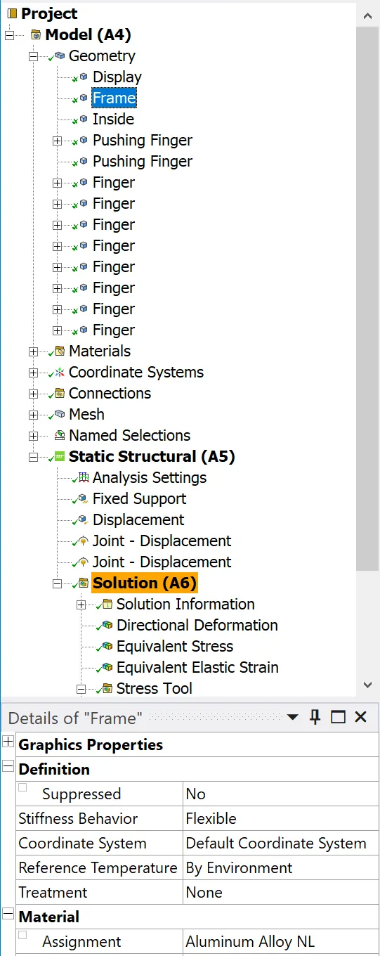
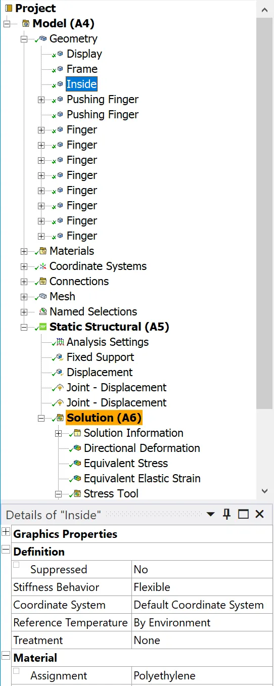
Assign Aluminum alloy NL material to frame, Glass to Display and Polyethylene to the inside motherboard of iPhone, Structural steel to all fingers.
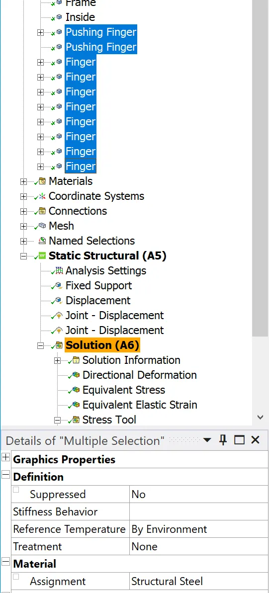
Assign bonded contact between display and frame
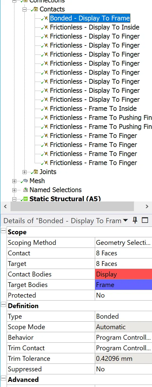
Assign Frictionless contact between Display and Inside, Display and finger, Frame and inside, Frame and pushing finger, Frame and finger.
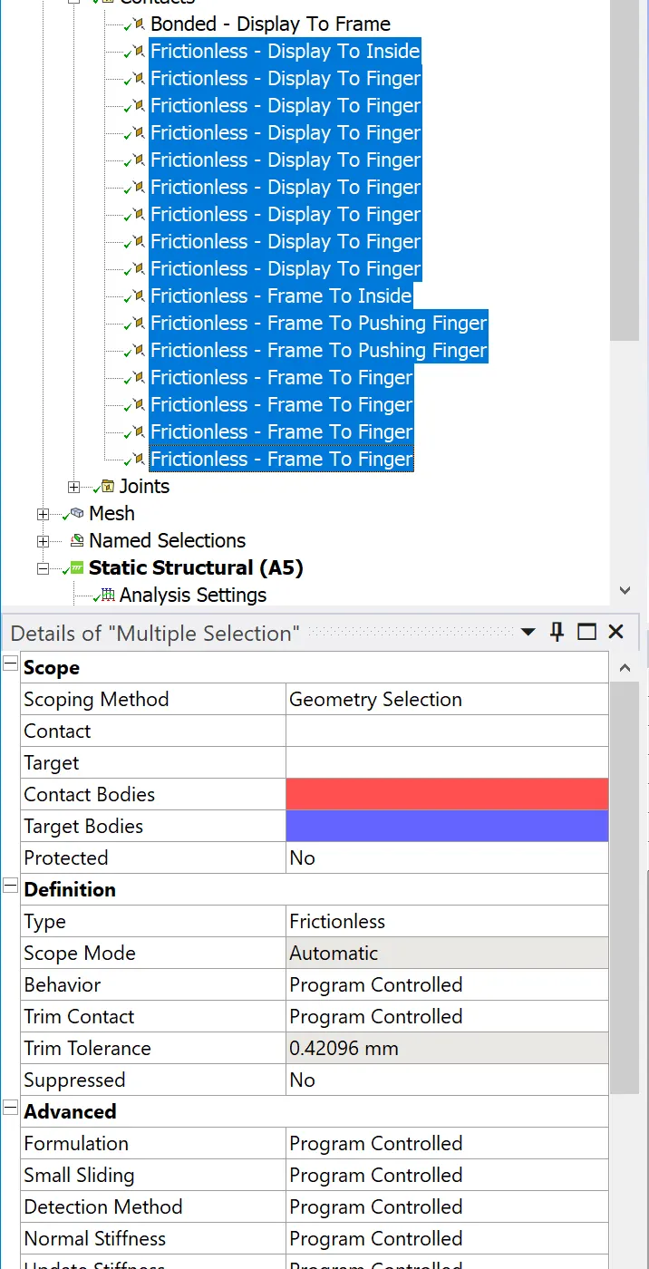
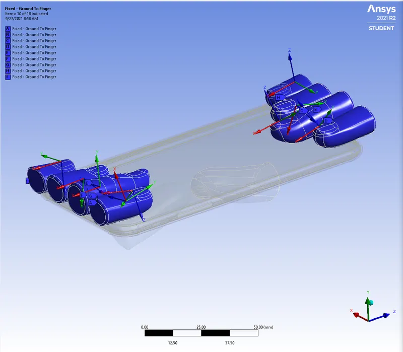
Assign Fixed joint for fingers
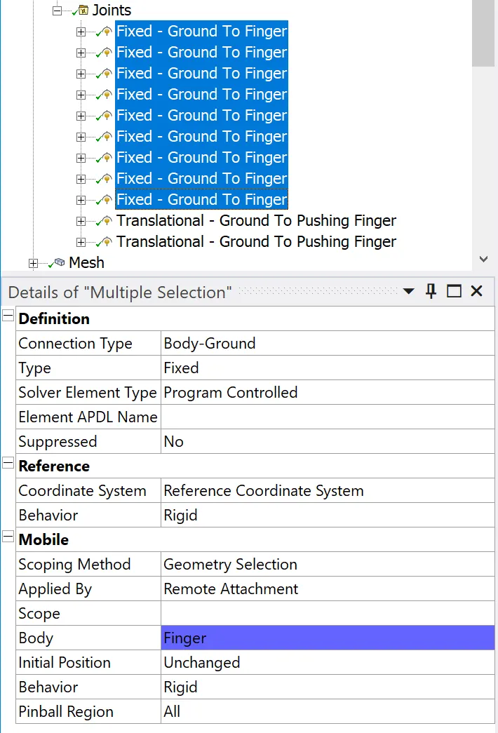
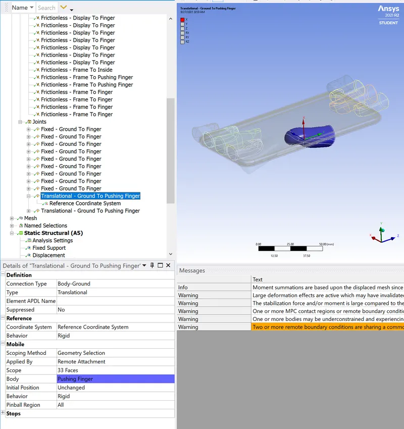
Assign translational joint for pushing fingers
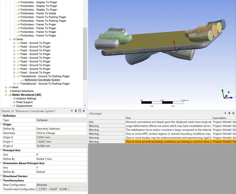
Change reference coordinate system by defining Principle axis related to the global Y-axis
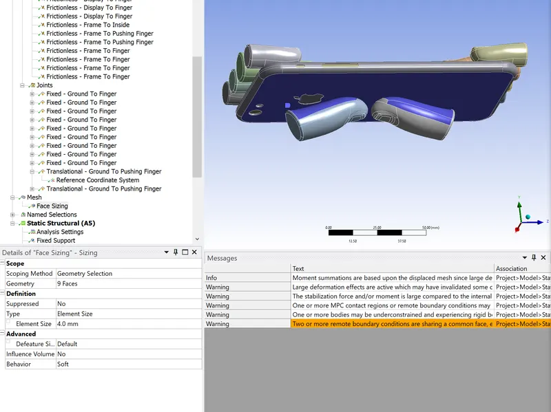
Apply face sizing of 4mm
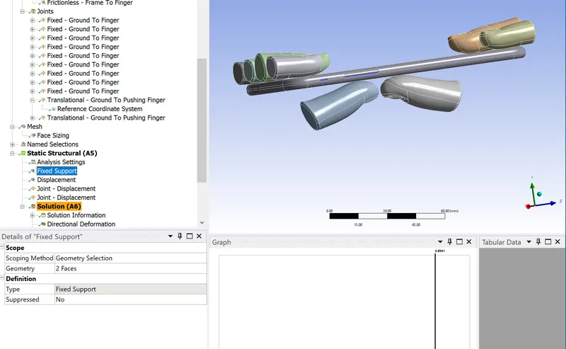
Apply fixed support
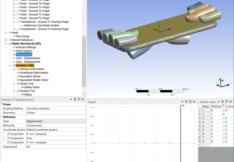
Apply displacement in the Y direction by restricting X and Z components.
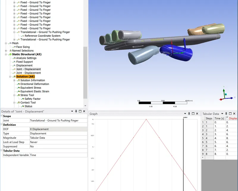
Apply joint displacement for one pushing finger and input magnitude in the form of tabular data.
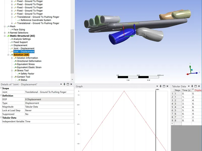
Perform the same operation for other pushing fingers
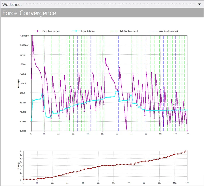
Case 2
Input cycles and stress data for the S-N curve as per the data given for Aluminum alloy.
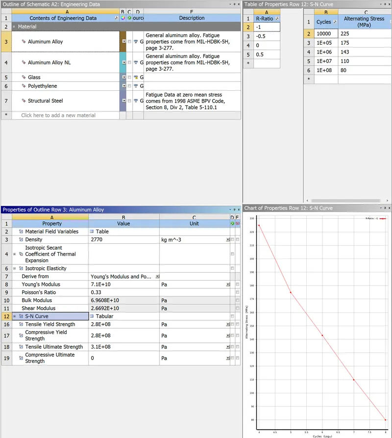
Simulate as per the steps mentioned in case 1. Include fatigue tool >> Life for solution
3. Results of case 1
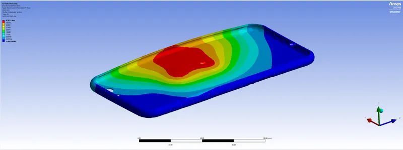
Fig 1 Directional deformation
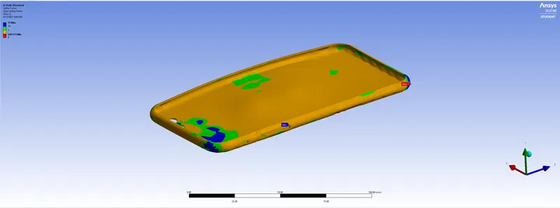
Fig 2 Safety factor
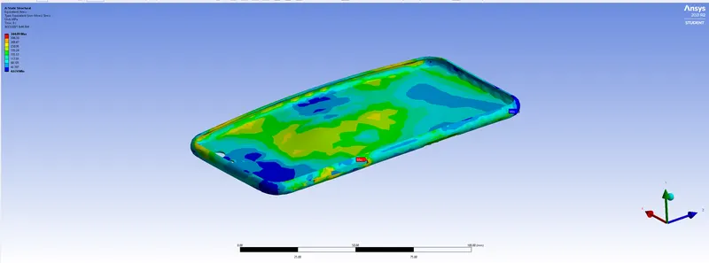
Fig 3 Stress
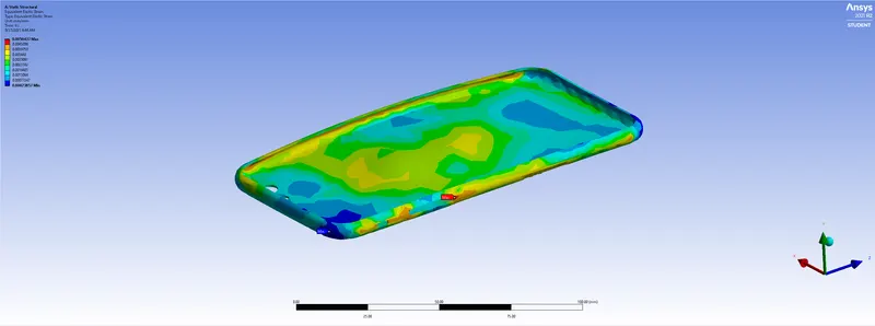
Fig 4 Strain
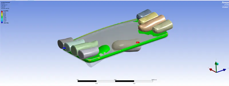
Fig 5 Contact pressure
4. Results of case 2
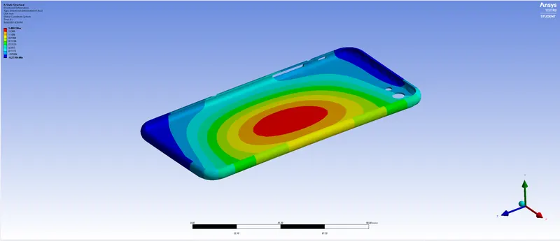
Fig 6 Directional deformation
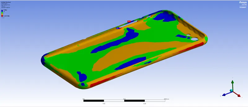
Fig 7 Safety factor
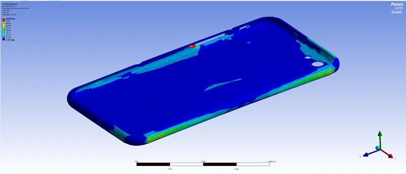
Fig 8 Stress
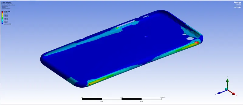
Fig 9 Strain
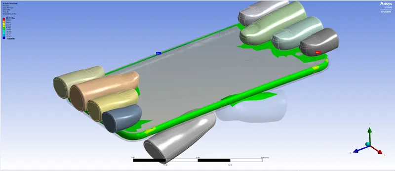
Fig 10 Contact pressure
5. Results, conclusion and report presentation
Case 1
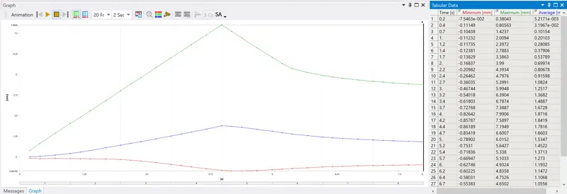
Fig 11 Graph of directional deformation
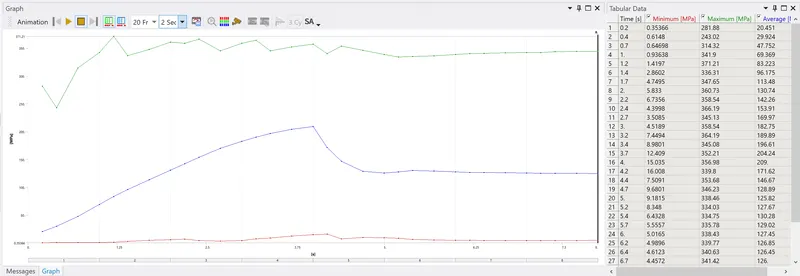
Fig 12 Graph of equivalent stress
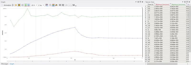
Fig 13 Graph of Equivalent elastic strain
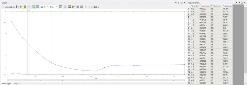
Fig 14 Graph of Safety factor
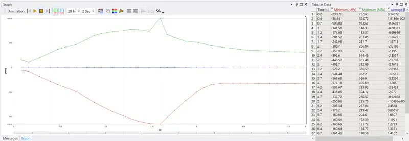
Fig 15 Graph of contact pressure
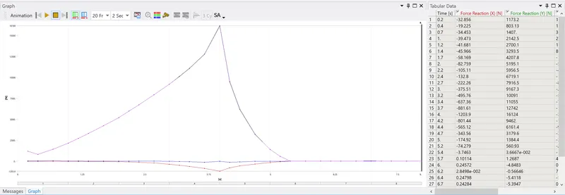
Fig 16 Graph of Force reaction
Case 2
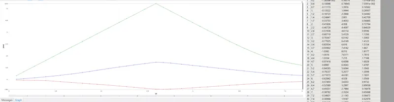
Fig 17 Graph of directional deformation
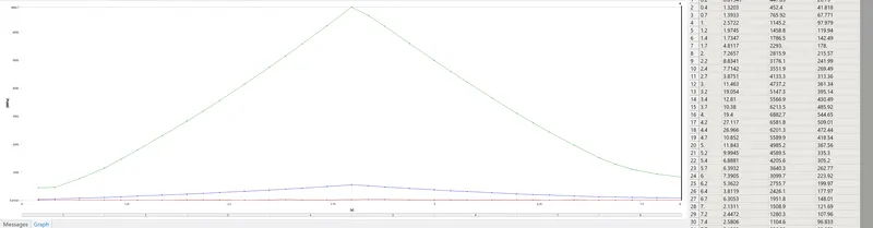
Fig 18 Graph of directional deformation
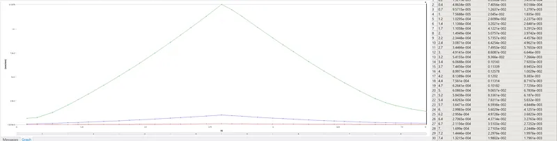
Fig 19 Graph of equivalent elastic strain
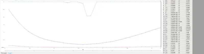
Fig 20 Graph of safety factor
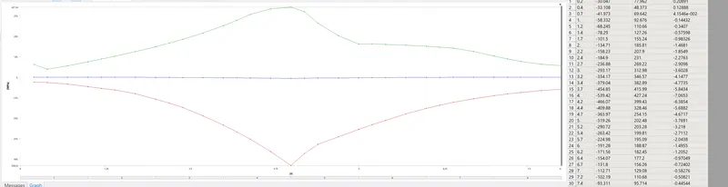
Fig 21 Graph of contact pressure
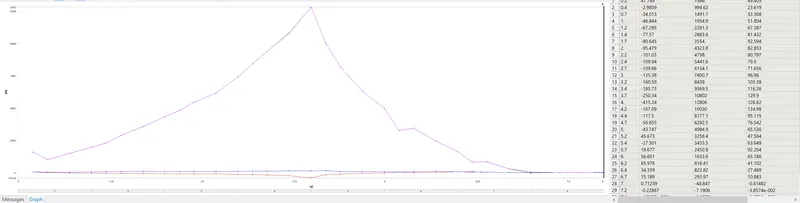
Fig 22 Graph of force reaction
Case 1
| Directional deformation | 4.3611mm |
| Safety factor | 15 |
| Stress | 344.09 MPa |
| Strain | 5.0437e-3 |
| Contact pressure | 153.18 MPa |
Case 2
| Directional deformation | 1.4802mm |
| Stress | 820.86 MPa |
| Strain | 0.013803 |
| Safety factor | 15 |
| Life | 1e8 |
| Contact pressure | 69.693 MPa |
Negative values in Fig 1 shows that the force applied by fingers is being removed. If we look at steps 1 to 4, displacement goes on increasing, reaches at peak value and then starts decreasing. Stress is higher at the edges (near the buttons of iPhone) and is uniformly distributed across the surface. Same scenario occurs for strain. Also contact pressure is higher at the edges. Directional deformation is higher in case 1 compared to case 2. Stress and strain is higher in case 2 and contact pressure is higher in case 1.
6. Simulation files
Drive link has all files.
https://drive.google.com/file/d/1PZCO1lk8rPqUWIZmFr5-sONh-otM4kVf/view?usp=sharing
https://drive.google.com/file/d/1sBLerTKBydYbg1IHWvG7S31e6CR1mKiY/view?usp=sharing