Week 5 Bending of iPhone
iPhone 6s BENDING SIMULATION AND ANALYSIS
AIM:
To perform a simulation and analysis of an iPhone 6S using two different cases! and to determine the fatigue life of the material in the iPhone.
Case 1: perform the analysis as per the model in its default position.
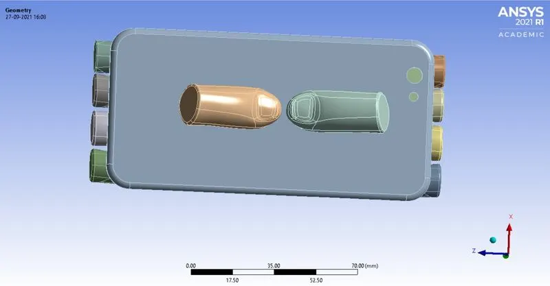
Case 2: move the bottom fingers to x = 22.5 mm and z = 10 mm, and perform the analysis.
MODEL:
The given model consists of iPhone comprised of display, frame and electronic circuit body and the fingers.
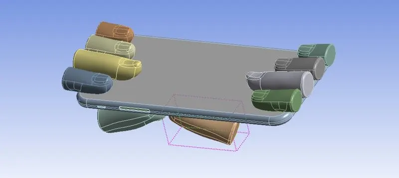
MODEL-2:
MATERIAL USED:
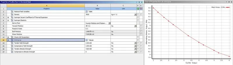
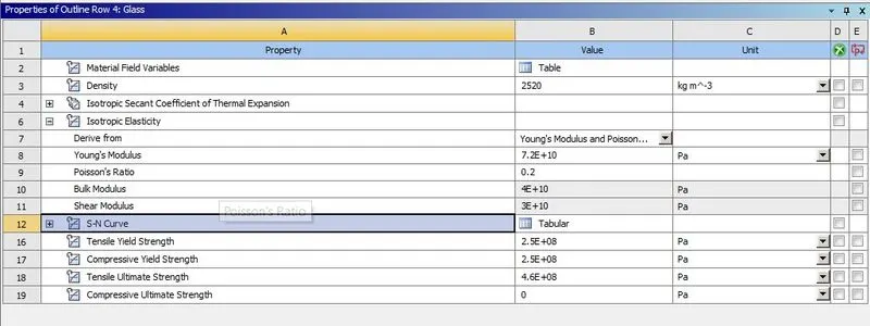
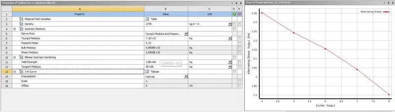
The materials used to perform the analysis are: fingers with structural steel and the frame of the iPhone with aluminum alloy NL and the display and the electronic body of the mobile with glass
STRUCTURAL STEEL :
GLASS:
ALUMINIUM ALLOY NL :
CONNECTIONS:
CONTACTS:
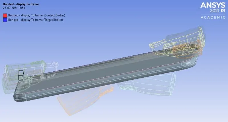
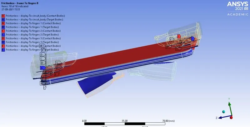
The default contacts were been detected by the software itself, where the unwanted contacts between the fingers need to be deleted and we need to proceed with the other default contacts made and the type of contact between display and the electronic circuit body should be bonded and the other contacts were given with frictionless contacts.
BONDED CONTACT :
FRICTIONLESS CONTACT :
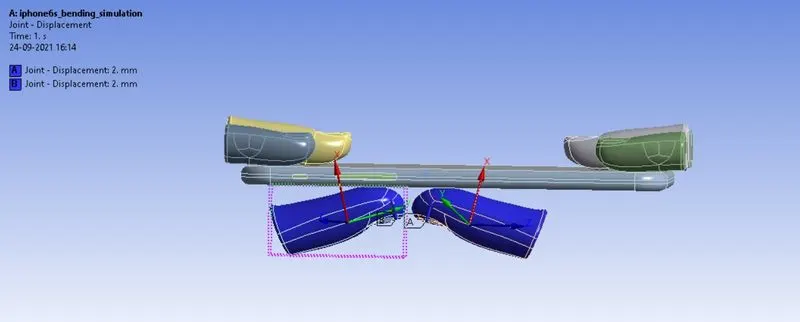
JOINTS:
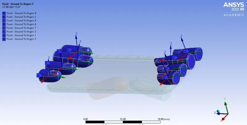
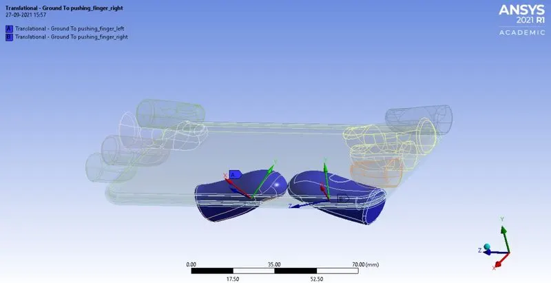
Joints were given to the fingers, in order to provide additional support to the model and the simulation to carry out properly, in this case the pushing fingers were provided with translational joints and the holding fingers were given with fixed joints.
FIXED JOINT :
TRANSLATIONAL JOINT :
MESH:
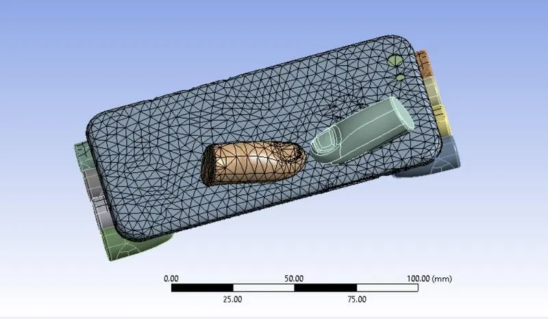
We are using the grid dependency method for the model to create the default mesh by the software itself, and we are introducing the face sizing method to determine the accurate results on the faces where the forces were experiencing the most. we made a face meshing of 4 mm on the back side of the frame and the pushing fingers contact faces.
ANALYSIS SETTINGS:
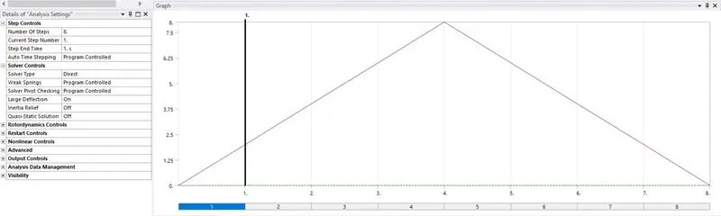
The analysis has been carried out in 8 steps, where the type of solver is set to direct, auto time steps were set to program controlled and the weak springs were been set to program controlled.
FIXED SUPPORT:
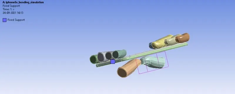
The fixed support been given to the electronic circuit body, where the screen and the electronic body is kept to be bonded. so that during the application of the force, we can assure that there is no slip between these two contacts.
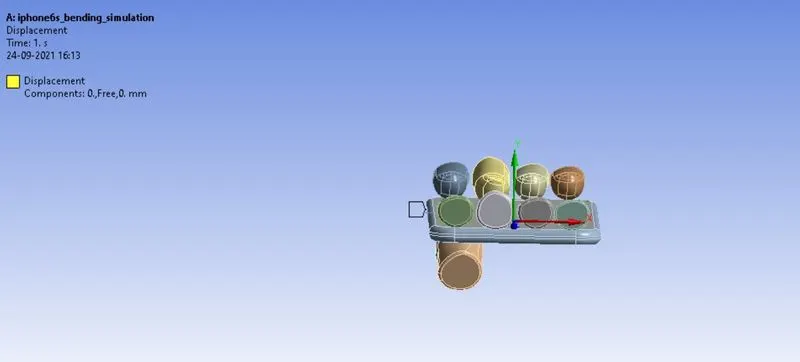
DISPLACEMENT:
The displacement has been given to the frame on the side faces and it is constrained on the x and z axis respectively, so that is kept free on the y- axis.
JOINT LOADS:
The pushing finger is the one producing force to carry the simulation, in that case the translational loads were given to the pushing fingers in the positive y direction.

CASE 1:
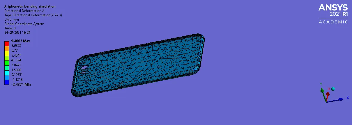
DIRECTIONAL DEFORMATION:
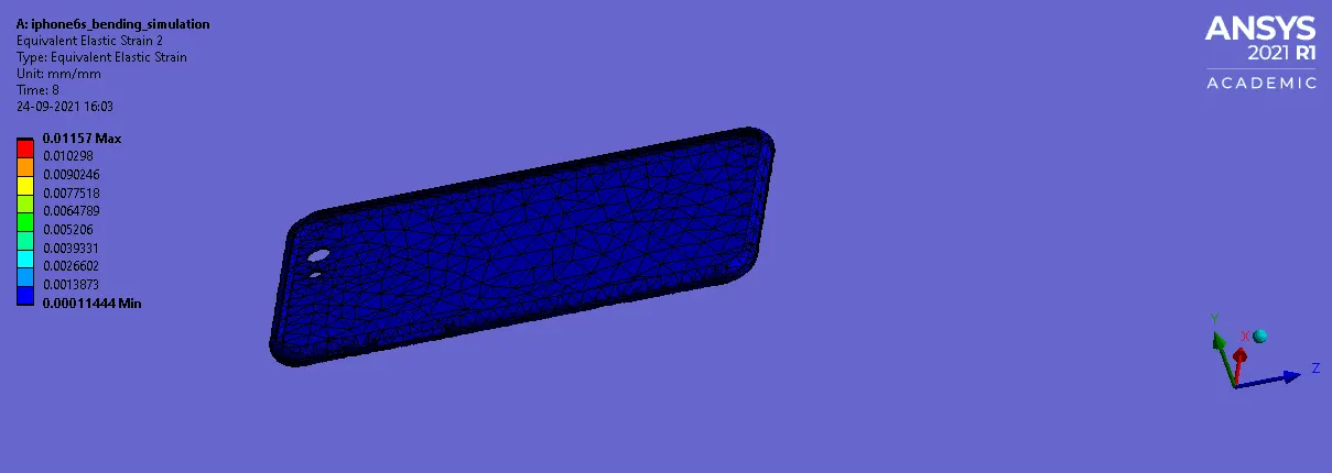
EQUIVALENT ELASTIC STRAIN:
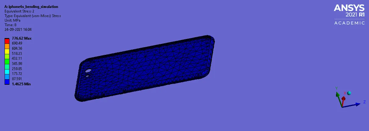
EQUIVALENT STRESS:
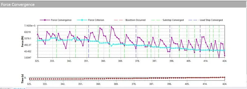
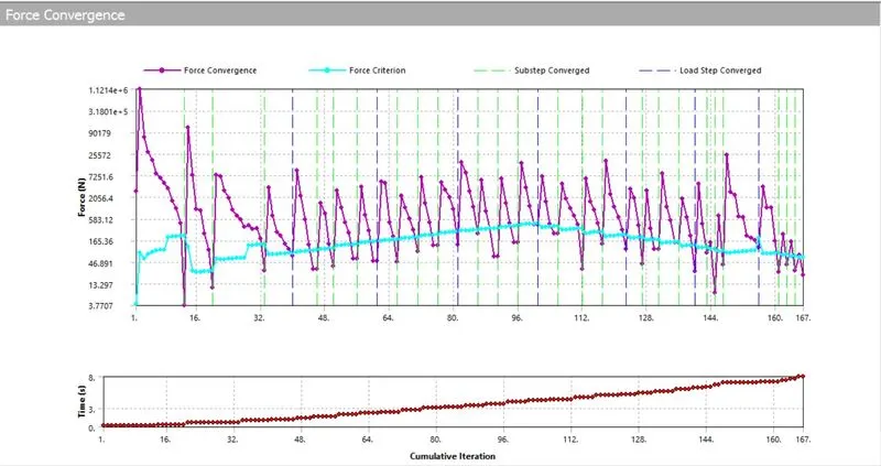
FORCE CONVERGENCE:
CASE 2:
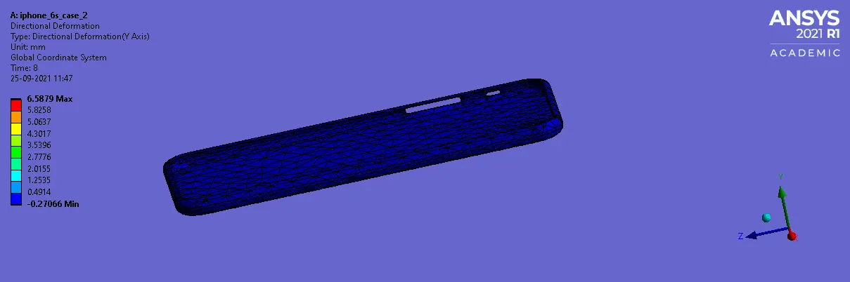
PUSHING FINGERS POSITION CHANGED TO X=22.5 mm AND Z= 10 mm.
DIRECTIONAL DEFORMATION:
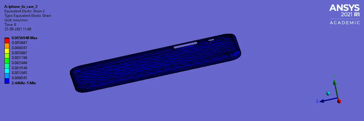
EQUIVALENT ELASTIC STRAIN:
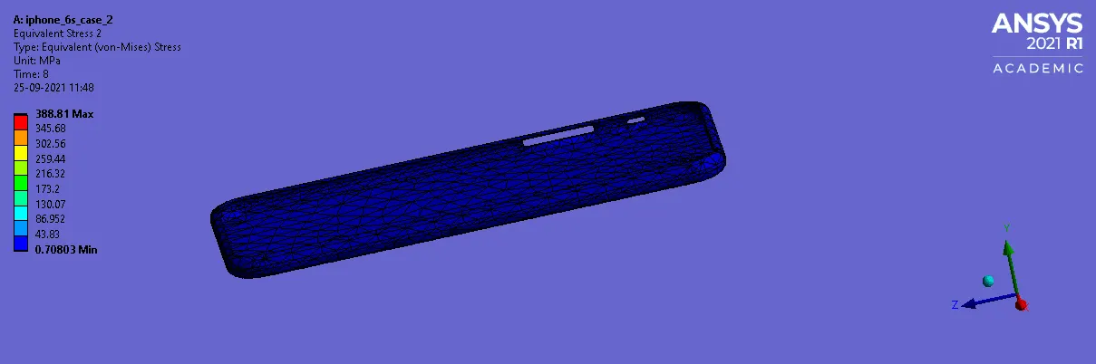
EQUIVALENT STRESS:
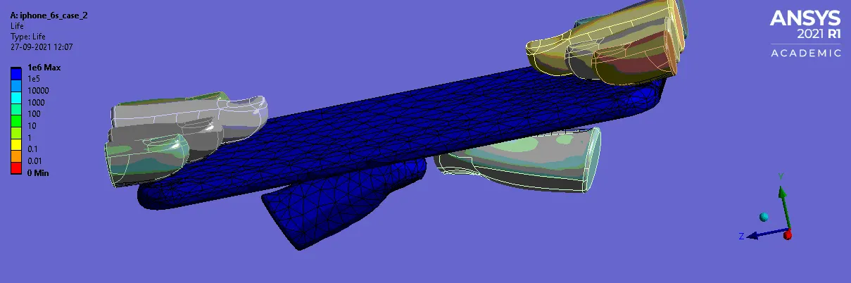
LIFE:
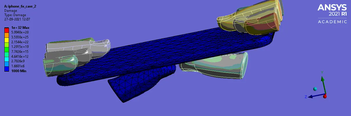
DAMAGE:
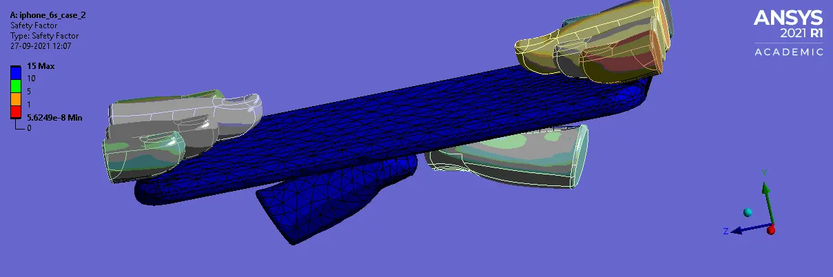
SAFETY FACTOR:
FORCE CONVERGENCE:
CONCLUSION:
From the above 2 cases , we came to conclude that , the case 2 experiences less stress with the same load , where as in the first case , it experiences double times than the second case . due to uniform
loading at the middle of the frame , case 2 is recommended for better use .