Week 5 Bending of iPhone
AIM:
To simulate the bending of iPhone.
OBJECTIVE:
This challenge is to simulate the bending of the iPhone using Ansys workbench with two different cases.
Case 1: The setup and geometry would be at the same position mentioned in the video.
Case 2: Move the fingers from their defined position to the given position x = 22.5mm & z = 10mm and obtain the result for the simulation. Also, define the S-N curve for the aluminum alloy material as per given values.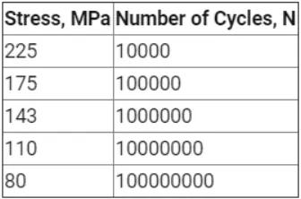
PROCEDURE:
. Select Static Structural, drag and drop it into the Project Schematic.
. Choose materials i.e Structural Steel, Aluminium Alloy NL, Glass and Polyethylene under Engineering Data.
. Add the given tabular data under SN Curve of Aluminium Alloy NL in Engineering data for case 2.
. Under geometry tab, import the given geometry, double-click to open Space Claim to register the model and then updat it.
. Then in Mechanical Module, assign Structural Steel to the fingers, Aluminium Alloy NL to the frame, Glass to the display and polyurethane to the insides of the iPhone.
. Assign a bonded connection between the display and the frame.
. The other connections including display to insides, display to fingers, frame to insides, frame to fingers can be left frictionless.
. All the fingers can be assigned a fixed joint except for the pushing fingers (thumbs). The pushing fingers are provided with translational joints.
. The mesh size was set to 3.5mm, and the pushing fingers’ upper faces were given a 1.5mm face sizing.
. Under static structural tab, we set the analysis to 8 steps with auto timestep as programmed.
. The upper and lower faces (vertically) of the frame are given a fixed support.
. The left and right faces (horizontally) of the frame are allowed a displacement along Y axis.
. Both the pushing fingers are given a joint displacement along Y-axis in 8 steps, ensuring it pushes the frame and retreats.
. Directional Deformation in Z-axis, Equivalent Plastic Strain and Equivalent Stress plots are requested from the solver as outputs.
. Also requesting Fatigue tool gives us life and safety factor.
. Run the simulation by clicking on SOLVE.
. Repeat the same steps in case 2, but after moving the pushing fingers by (22.5, 0, 10) and defining SN Curve.
These are the below condtions or loads used to simulate the model:
MATERIAL PROPERTIES
ALUMINIUM ALLOY NL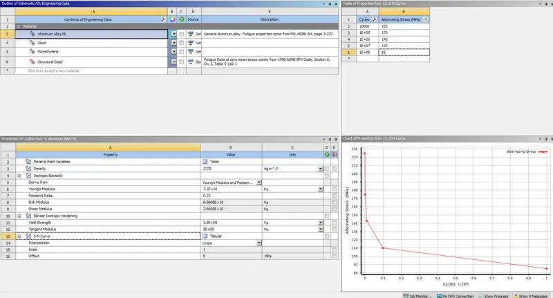
GLASS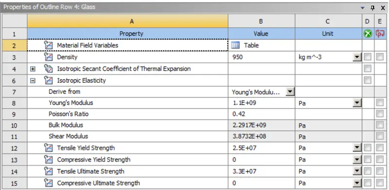
POLYEHYLENE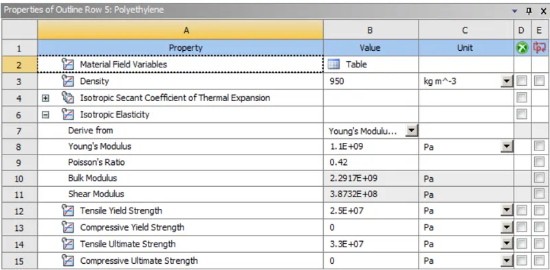
STRUCTURAL STEEL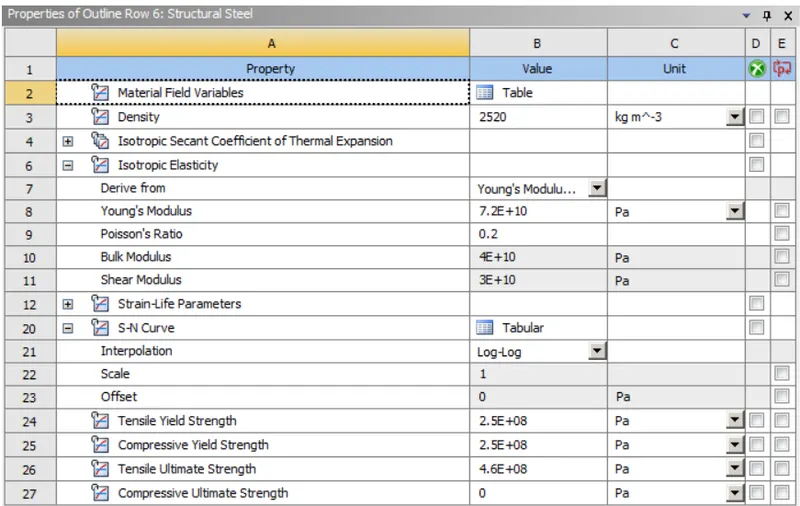
CONTACTS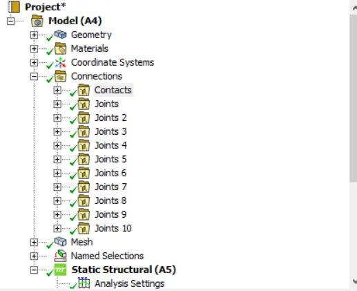
FIXED SUPPORT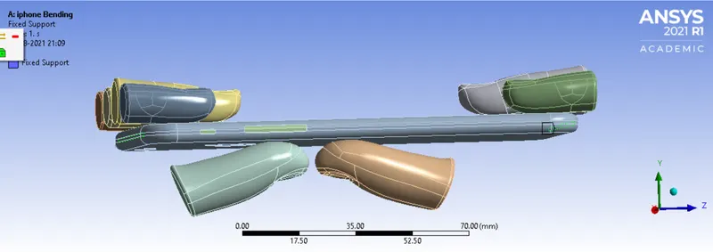
JOINT DISPLACEMENT 1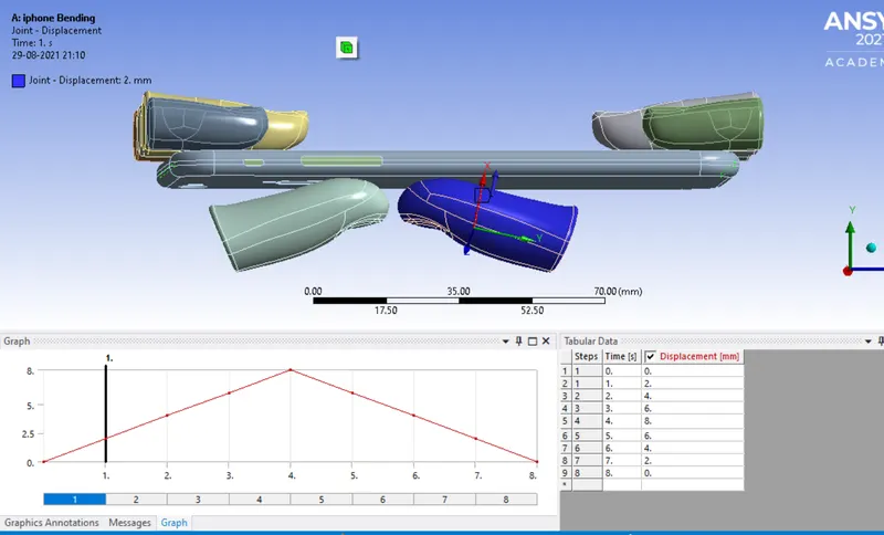
JOINT DISPLACEMENT 2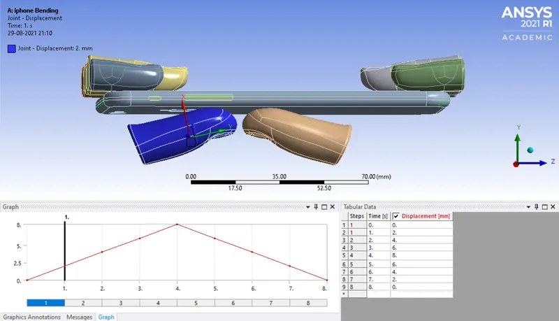
DISPLACEMENT OF FRAME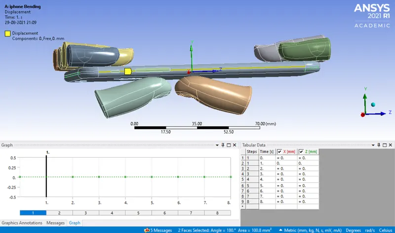
MESHING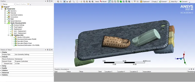
CASE 1: Boundaries condition as per the video
DIRECTIONAL DEFORMATION (MODEL)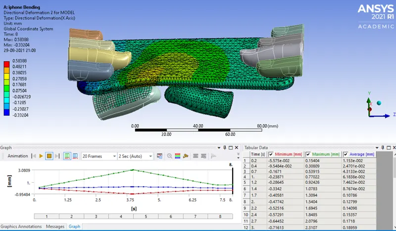
EQUIVALENT STRESS (ON FRAME)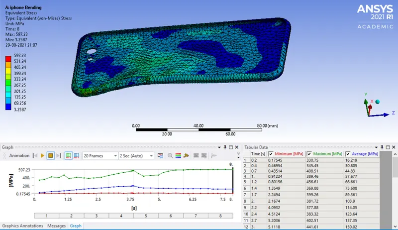
EQUIVALENT ELASTIC STRAIN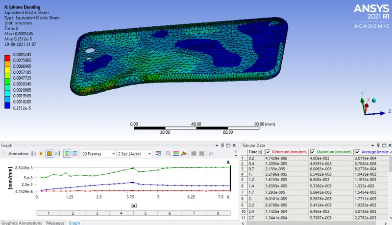
DIRECTIONAL DEFORMATION (FRAME)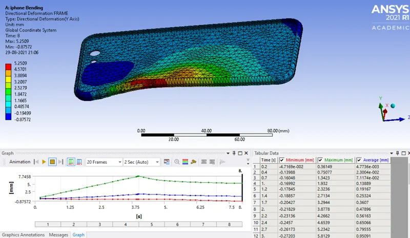
CASE 2: Boundaries condition as per SN curve and changing the axis of fingers.
DIRECTIONAL DEFORMATION(BODY)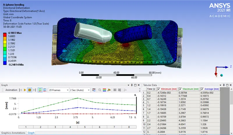
DIRECTIONAL DEFORMATION(FRAME)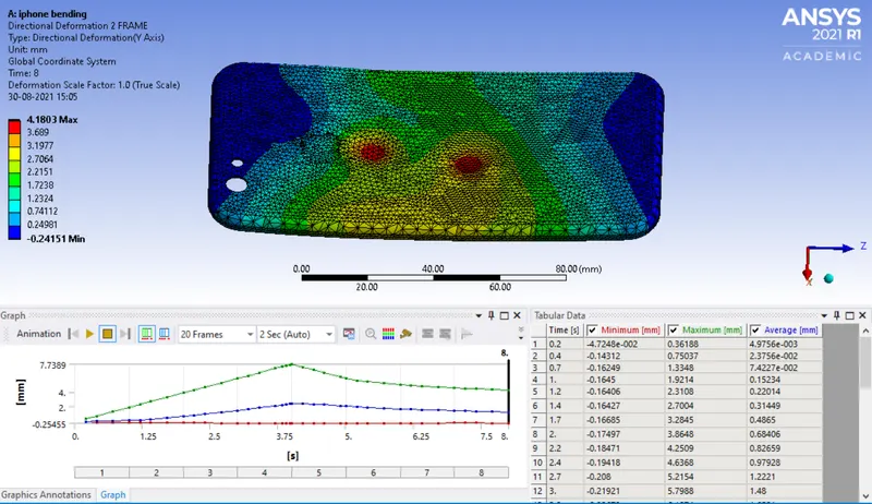
EQUIVALENT STRESS(FRAME)
EQUIVALENT ELASTIC STRAIN(FRAME)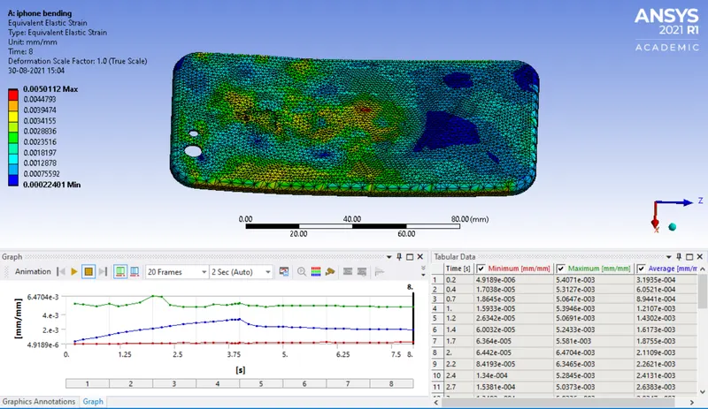
SAFETY FACTOR(FRAME)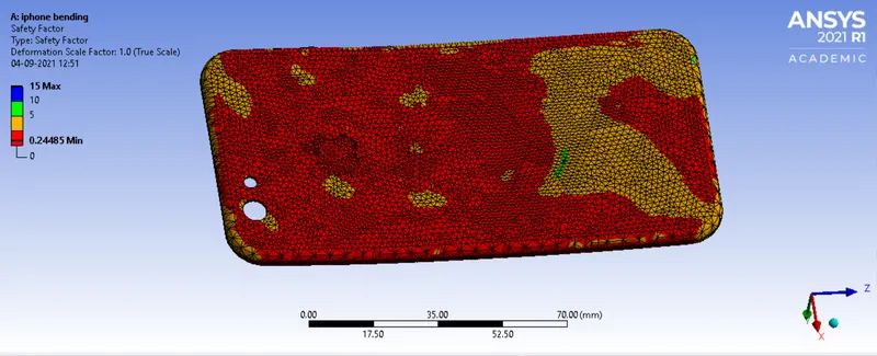
LIFE(FRAME)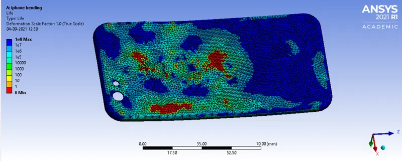
RESULTS AND CONCLUSION:
These are the results for stresses and strains acting on the frame alone.
|
Case |
Stress in Al-Alloy NL (MPa) |
Strain in Al-Alloy |
Directional Deformation (mm) |
|
Case 1 |
597.23 |
0.0085245 |
5.2509 |
|
Case 2 - Thumbs Moved by (22.5,0,10) & Defined SN CURVE |
347.16 |
0.0050112 |
4.1803 |
We can observe that the stress, strain and deformation has reduced after moving the position of pushing fingersand feining SN curve to aluminium alloy NL (used in frame).