Week 5 Bending of iPhone
OBJECTIVE:-
To simulate the model for bending of an iphone as per the cases below:-
- Case 1 – Simulate the model as per the steps in the video we studied.
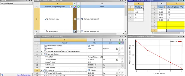
- Case 2 – Move the fingers to the given position X=22.5 mm & Z=10 mm and simulate the model. Also define the S-N curve for the Aluminium Alloy material as per values given below and determine the fatigue life results for the same.
|
Stress, MPa |
Number of Cycles, N |
|
225 |
10000 |
|
175 |
100000 |
|
143 |
1000000 |
|
110 |
10000000 |
|
80 |
100000000 |
Results to obtain:-
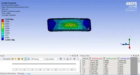
- Obtain the directional deformation for the model
- Factor of Aluminium Alloy NL
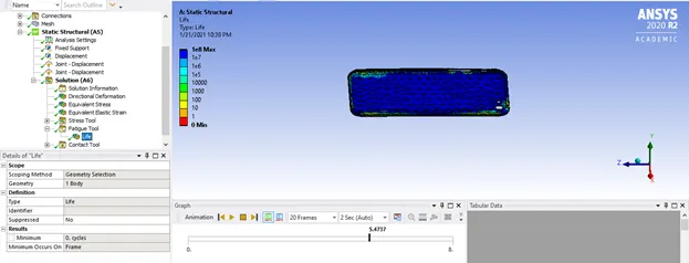
- Life of the Aluminium alloy for the case
- Compare the results and present with the conclusion.
PROCEDURE FOLLOWED:-
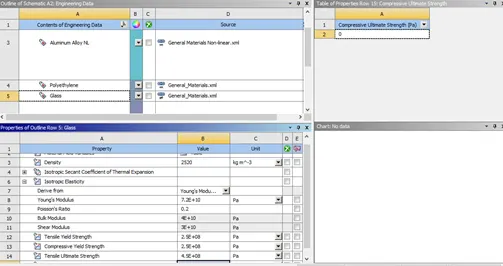
Create a new static structural material. And edit/add the materials required to be assigned to the material. In our model we will be adding Structural steel(Default), Aluminium alloy(General Materials),Polyethylene from the engineering data. Assign Glass properties to the polyethylene and make changes in the polyethylene itself to match to the properties to the glass.
Also aluminium alloy SN-curve has to be assigned values
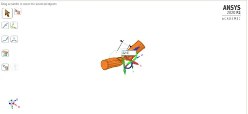
As we were given to move the pushing finger to X= 22.5 mm & Z= 10 mm, thus making changes in Space-claim to the pushing finger.
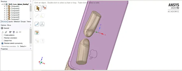
X = 22.5 mm
Z = 10 mm
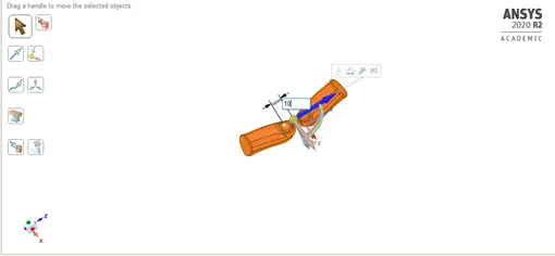
Since in the old position the pushing finger were somewhere else, whereas it has moved to some extent in current model
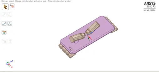
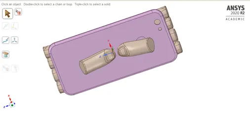
Save this model and proceed in mechanical workbench.
Rename all the components
Stiffness behavior= rigid for all fingers and 1 pushing finger.
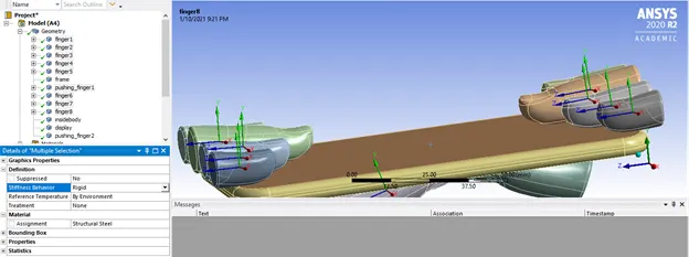
Assigning material,
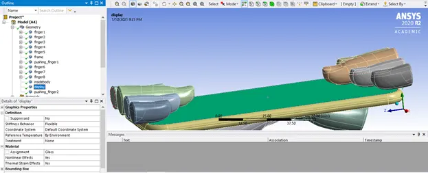
display = glass
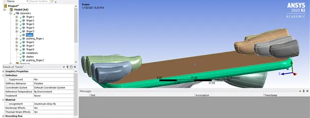
Frame = aluminium alloy
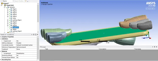
Inside body = polyethylene
Contacts between all the components except Display and frame
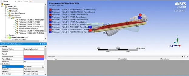
And in between display and frame = bonded
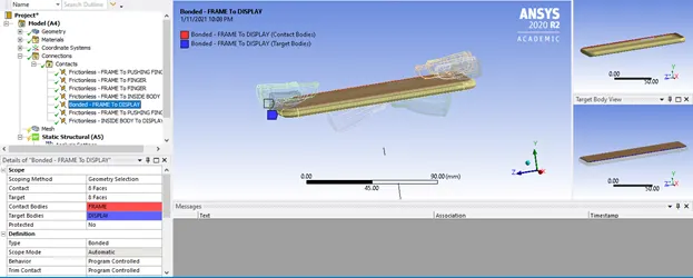
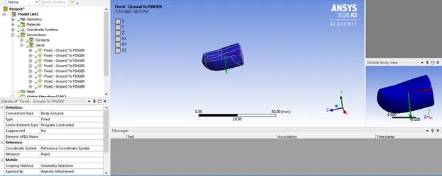
Joint = fixed for all the finger.
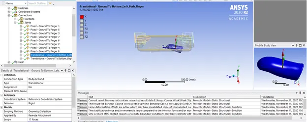
Insert joints = translational for both pushing finger and check for coordinates i.e. direction of translation.
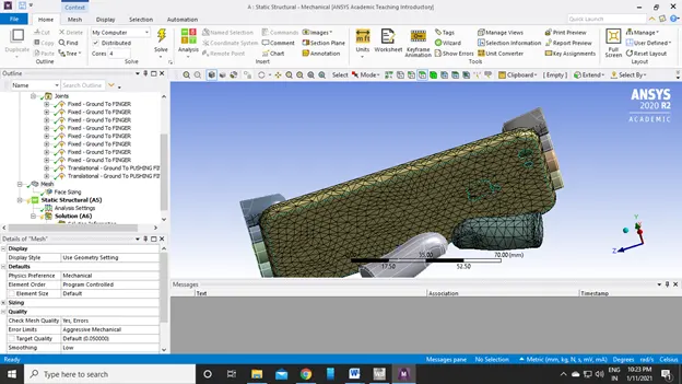
Give sizing for frame and pushing finger contact area = 4mm also from quality smoothening = LOW
and generate mesh
After all the contacts and joint setting, now its time to assign all the settings in Static structural,
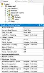
Analysis setting
Number of steps = 8
select all the 8 steps:
Large deflection = ON
Weak springs = program controlled
Solver type = Direct
Stabilization = constant
Energy dissipation ratio = 0.1
Activation for first sub-step = yes
Under output controls:
Change all NO to YES except contact miscellaneous.
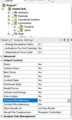
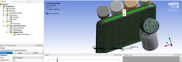
Now inserting fixed support
Hide the frame, and select the 2 side edges of the inside body
Insert displacement and select the faces
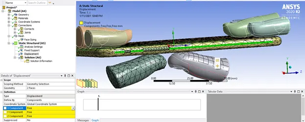
And restrict the motion in X & Z direction as the y- direction will only be having motion along
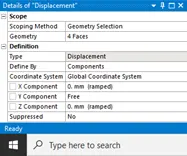
After the displacement we have to give a joint load for both pushing finger.
First pushing finger:
|
Time |
displacement |
|
0. |
0. |
|
1. |
2. |
|
2. |
4. |
|
3. |
6. |
|
4. |
8. |
|
5. |
6. |
|
6. |
4. |
|
7. |
2. |
|
8. |
0. |
Second pushing finger tabular data:
|
Time |
Displacement |
|
0. |
0. |
|
1. |
2. |
|
2. |
4. |
|
3. |
6. |
|
4. |
8. |
|
5. |
6. |
|
6. |
4. |
|
7. |
2. |
|
8. |
0. |
Since all the settings have been assigned now we have to solve the geometry. For solving the geometry the output results have to be given, thus in this model we need, Directional deformation for whole model, Safety factor for aluminium alloy & fatigue tool(Life) for the aluminium case.
Directional deformation:
Life of the Aluminium alloy case only:
Stress/Safety factor for the Aluminium alloy case only
CONCLUSION:-
The simulation is performed successfully and the results are tabulated below,
|
Directional Deformation(mm) |
Safety Factor |
Life of Alloy case(cycles) |
|
7.9791 |
15 |
1E+8 |