iPhone Bending Stimulation
OBJECTIVE:
To perform an IPhone bending stimulation as per the given cases below:
CASE 1: Stimulate the given model.
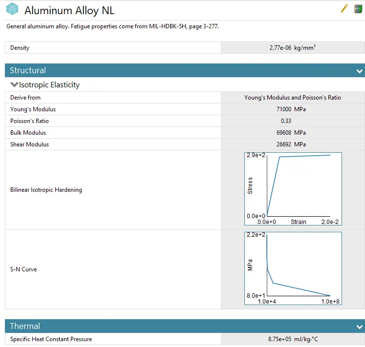
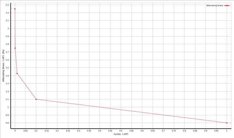
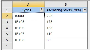
CASE 2: Move the bottom fingers from their defined position to the given position X = 22.5mm & Z = 10mm and obtain the results for the stimulation. Also define the S-N curve for the Aluminium Alloy material as per values given below and determine the fatigue life results for the same.
|
Stress, MPa |
Number of Cycles, N |
|
225 |
10000 |
|
175 |
100000 |
|
143 |
1000000 |
|
110 |
10000000 |
|
80 |
100000000 |
Obtain and compare the results of directional deformation, Equivalent Stress, Equivalent Strain, Safety Factor and life.
SOLUTION:
STEP 1) Model Design
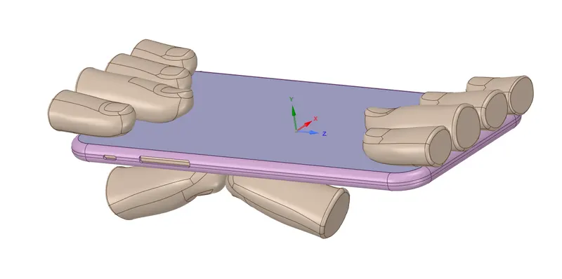
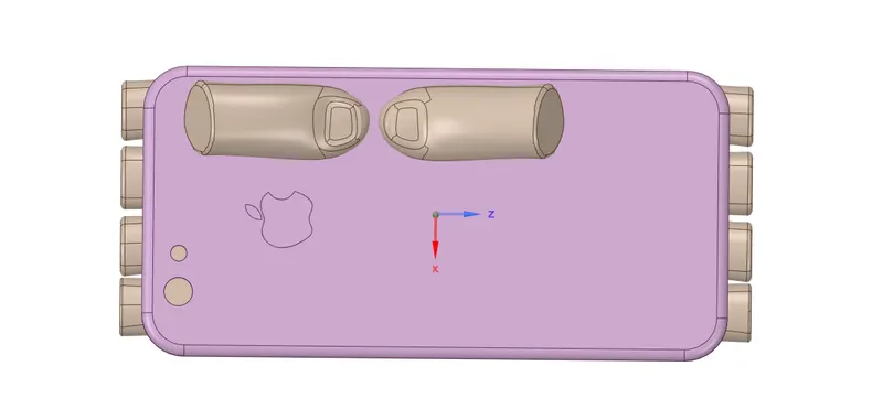
The model consist of an IPhone and figures. A number of faces in the model had to be merged, so that it becomes compatible with the academic version.
For case 1) the given model was used as shown in the figure.

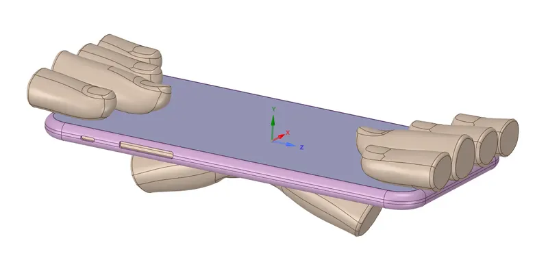
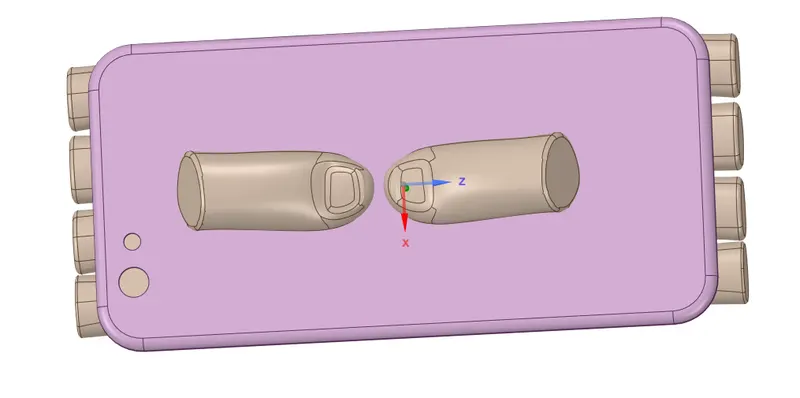
For case 2) the position of the pushing fingers have to be changed from its initial position to the given position X = 22.5mm and Z = 10mm. The modified model is shown in the figure.

STEP 2) Material
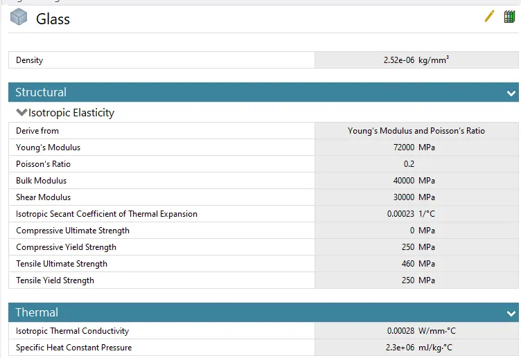
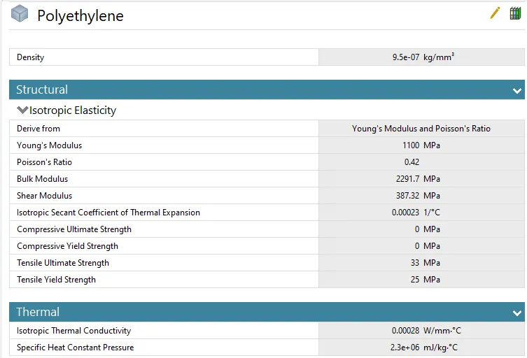
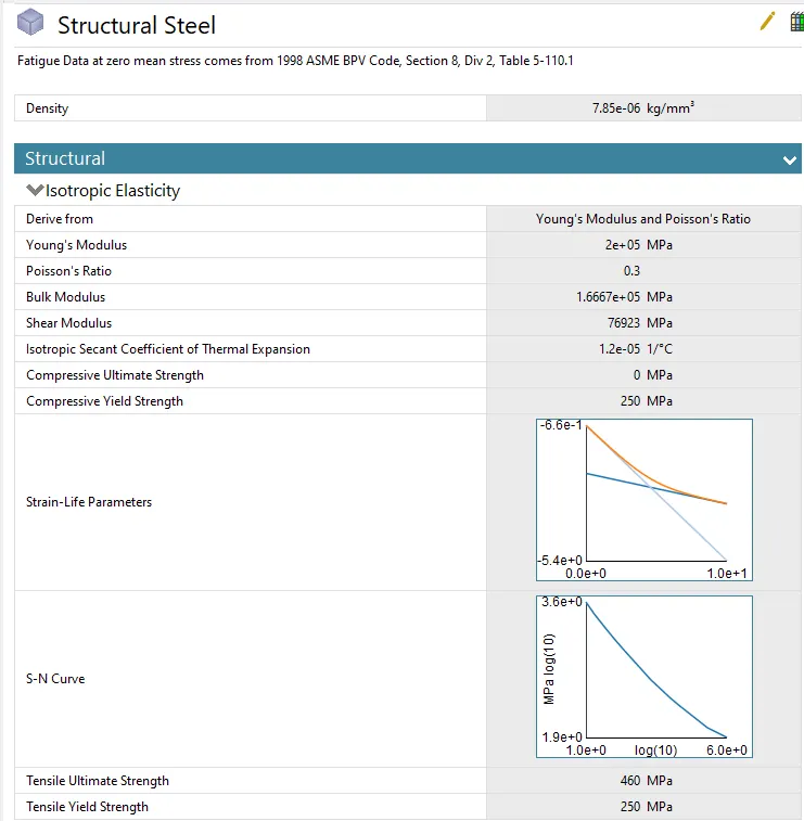
In this stimulation different parts in the model were assigned different materials; the display was assigned glass material, frame was assigned Aluminium alloy NL in case 1 and Aluminium alloy with modified S-N curve in case 2 and the insides of the phone body was assigned as polyethylene. All the fingers were assigned structural steel and all the fingers except one pushing finger were assigned stiffness behavior as rigid.
STEP 3) Connections
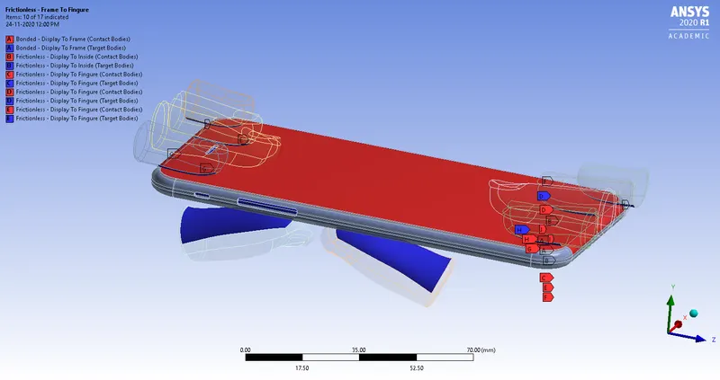
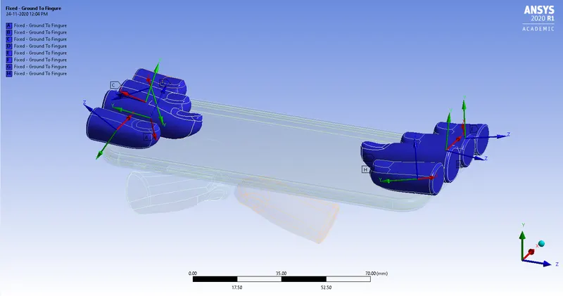
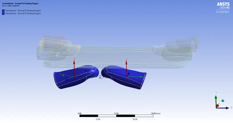
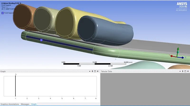
After the assignment of the material we have to define contacts. All contacts between the fingers and phone body were defined as frictionless. The contacts between the glass to frame was defined as bonded. After defining contacts, joints were defined. All fingers were assigned fixed join with connection type body to ground. And pushing fingers below the phone were defined translational joint.


STEP 4) Meshing
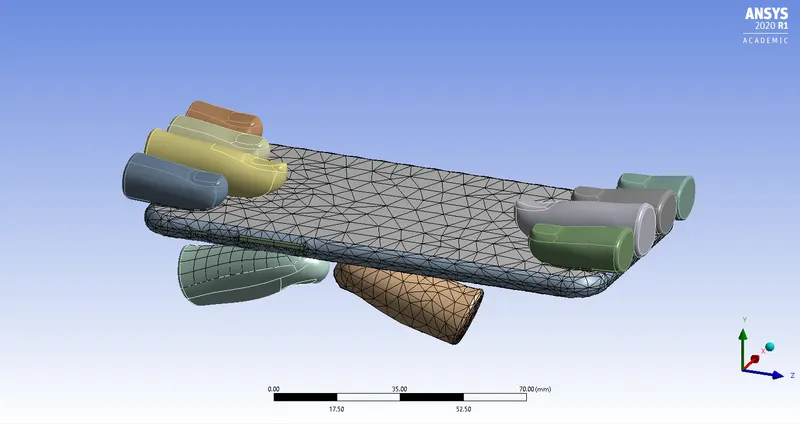
The model was meshed using ANSYS mesher. The bottom face of the IPhone case and the faces of the pushing fingers which are in contact with the case were given face sizing of 4mm. And the rest of the model was given default mesh size.

STEP 5) Analysis settings
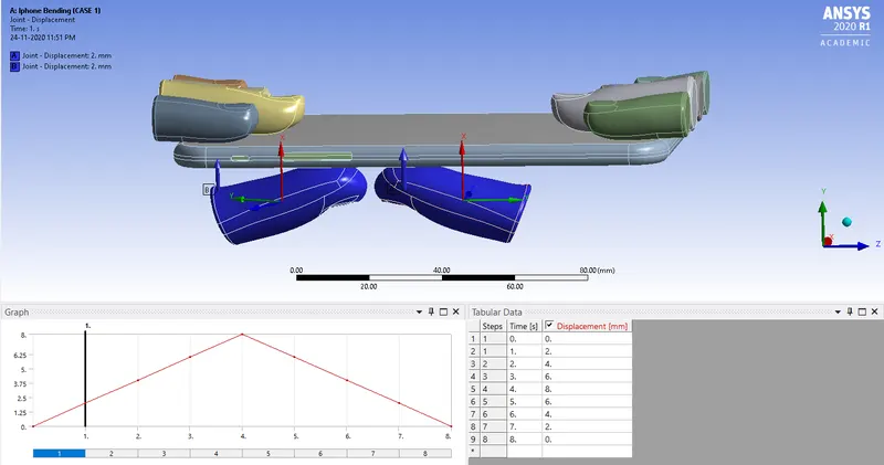
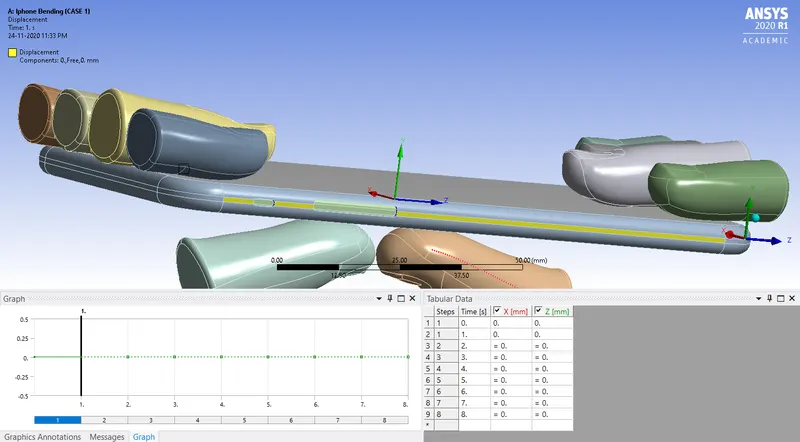
The analysis was carried out over in 8 steps. For each step, solver type is direct, weak springs to program controlled, large deflection was turned on and energy dissipation ratio of 0.1 was defined. As all the deformation is in Y direction, so the other two directions have to be fixed. So two opposite faces of the inside was fixed and the displacement of the frame in X-axis and z-axis are defined as zero. The two pushing fingers are given displacement up to 8mm against the frame and then retracted. These settings were same in both the cases.


STEP 6) Result
CASE 1)
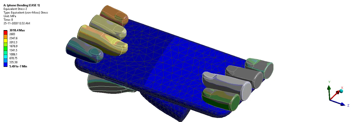
- Equivalent stress for the whole setup

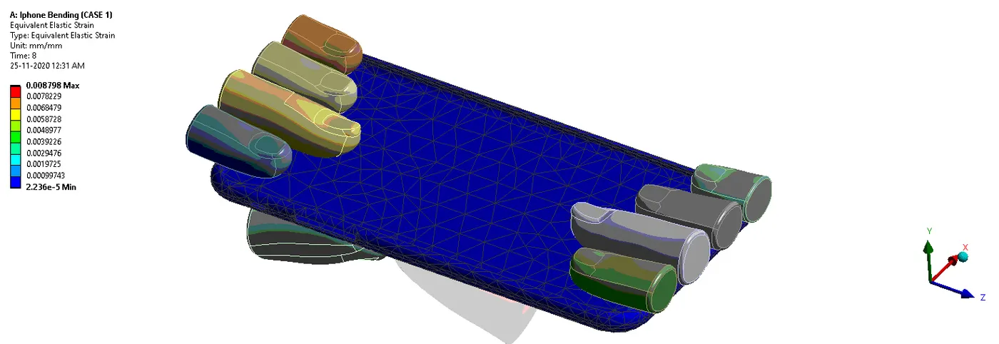
- Equivalent strain on the frame

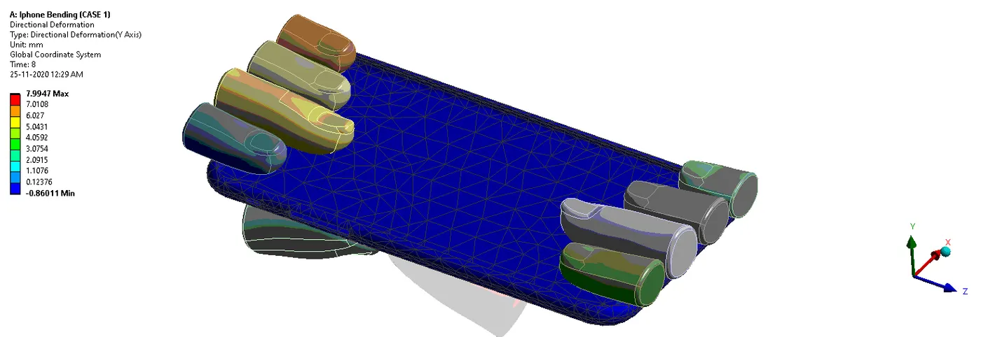
- Directional deformation in the Y axis for the frame

CASE 2)
- Equivalent stress for the whole setup
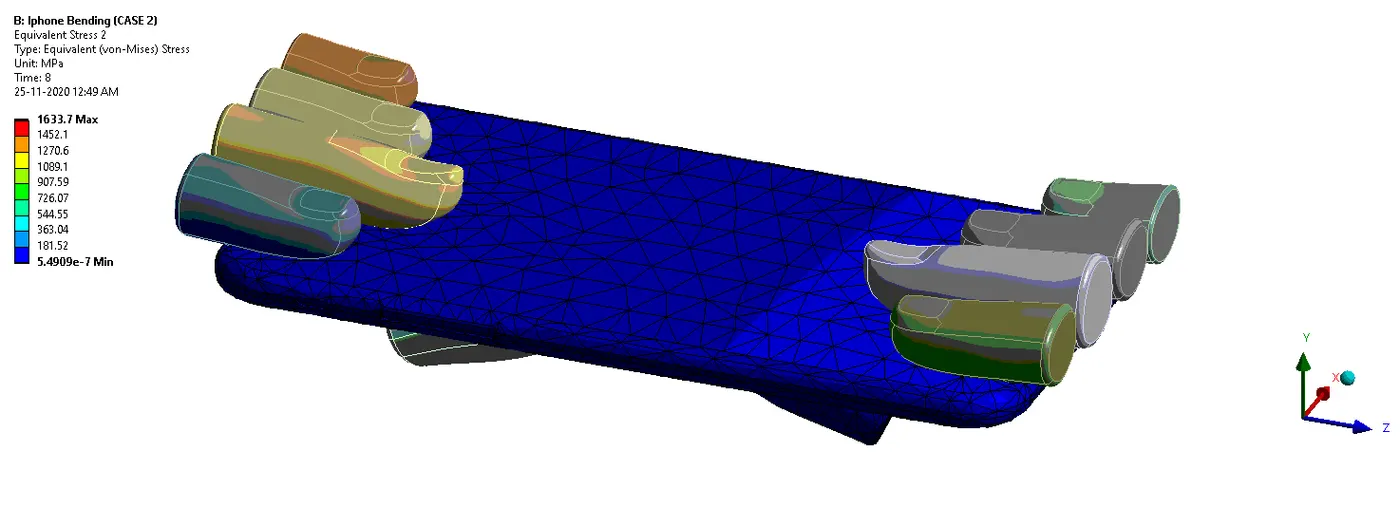
- Equivalent strain on the frame
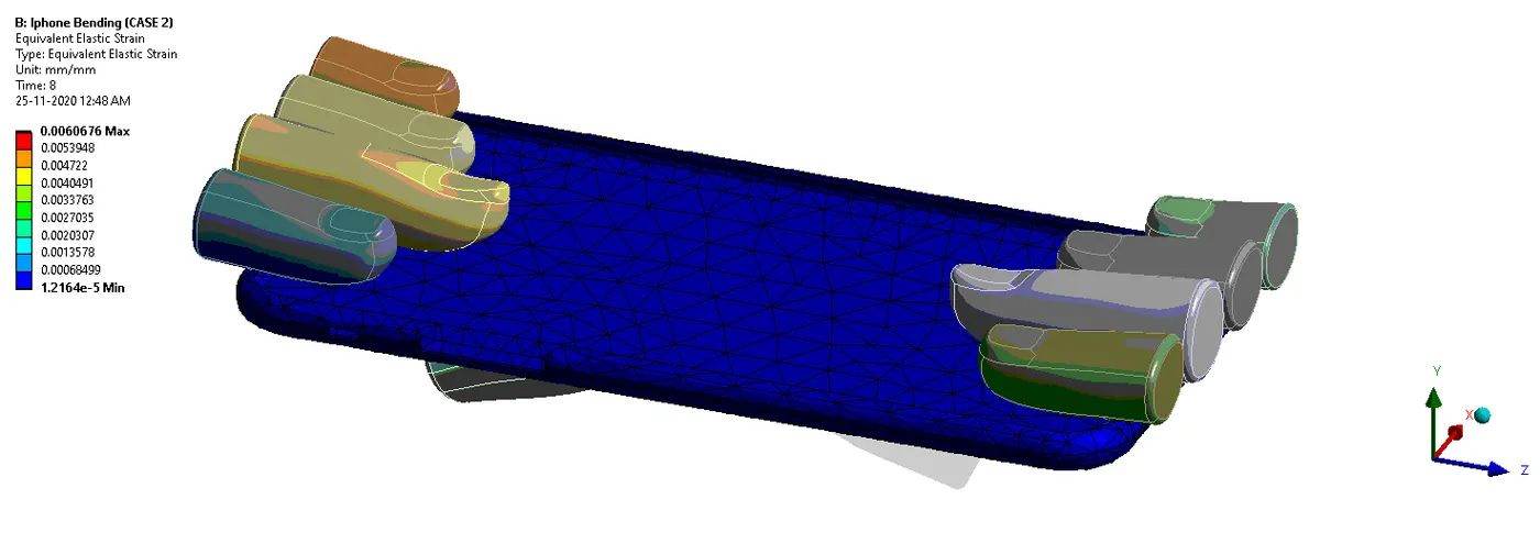
- Directional deformation in the Y axis for the frame
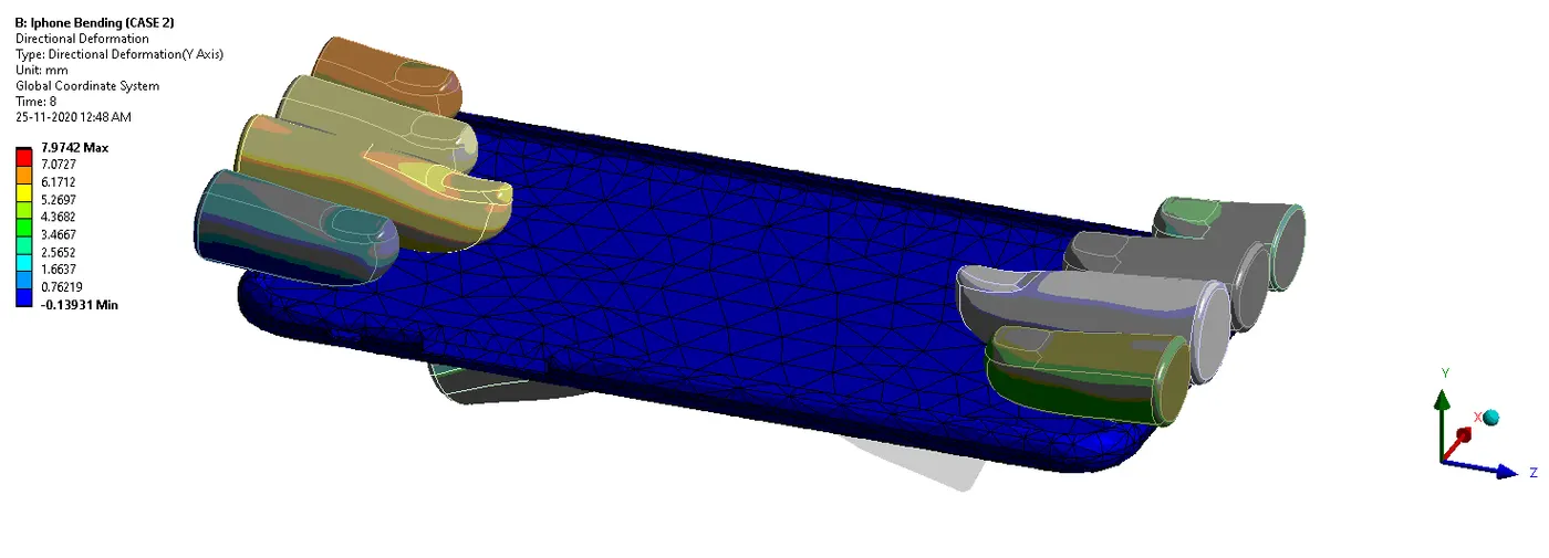
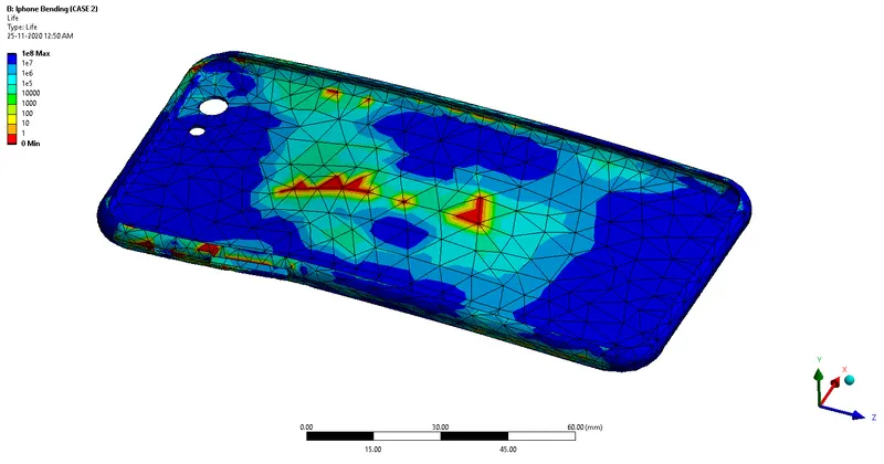
- Life

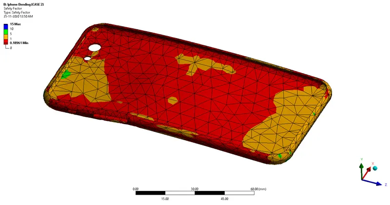
- Factor of Safety

CONCLUSION:
So the final results obtained are shown below:
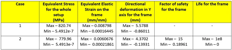
- From the above results, we will conclude that, stress is maximum in case 1 as compare to case 2 due to the loading from the center point of system because of uniform loading.
- From the inputted S-N curve we can see that the maximum portion of the phone has life more than 1e6 cycles.
- Directional deformation is less in case 2 as compare to case 1 because in case 2 phone retracted back more as compare to case 1.
Link of Analysis Files is attached.