Grid dependency test for bevel gear stimulation
OBJECTIVE: To perform a grid dependency test for the bevel gear stimulation for the mesh sizes of 6, 5 and 4 mm and evaluate the results for von-mises stress, equivalent elastic strain and total deformation using the mentioned mesh sizes.
SOLUTION:
Grid Dependency Test
Grid Dependency Test, Grid Independency Test and Mesh Refinement Test are all means the same. Grid dependency test is a method to find the optimum mesh size to solve a problem. Mesh size, along with the element shape and type, plays a very important role in obtaining a solution of good accuracy. In a general sense, it can be said that a very fine mesh will provide results of very high accuracy, but it will also significantly increase the computational time. So a grid dependency test is done to find the best mesh characteristics which will give the best results in reasonable time. Normally, the evaluation is initiated with a very coarse mesh and it is made finer over a period of time. As the mesh becomes fines the results produced by the stimulation becomes more close to the actual result and a point is reached, beyond which further refinement does not give a significant different result, which means the results are converged. Any further refinement will just increase the computation time while giving the same result or a result with minor changes. This mesh size is the most optimum fine mesh which can be used to solve the problem. The best mesh does not only depend on the size, but it also depend on parameters like element order, global and local mesh refinement, manual changes in the mesh etc. and this will change for different problems. Hence the grid dependency test is carried to find the best mesh parameters and to reduce our computation time.
STEP 1) Part Design
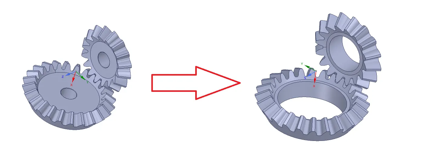
We have already provided with the model. But in this case we are only interested stress, strain and deformation produced in the gear teeth so the extra material is removed in SpaceClame. It is always important to remove unnecessary material from the analysis model, this will help to reduce computational time.

STEP 2) Material
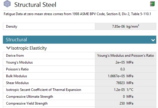
In this case both the gears were assigned structural steel and the material properties are given below.
STEP 3) Connections
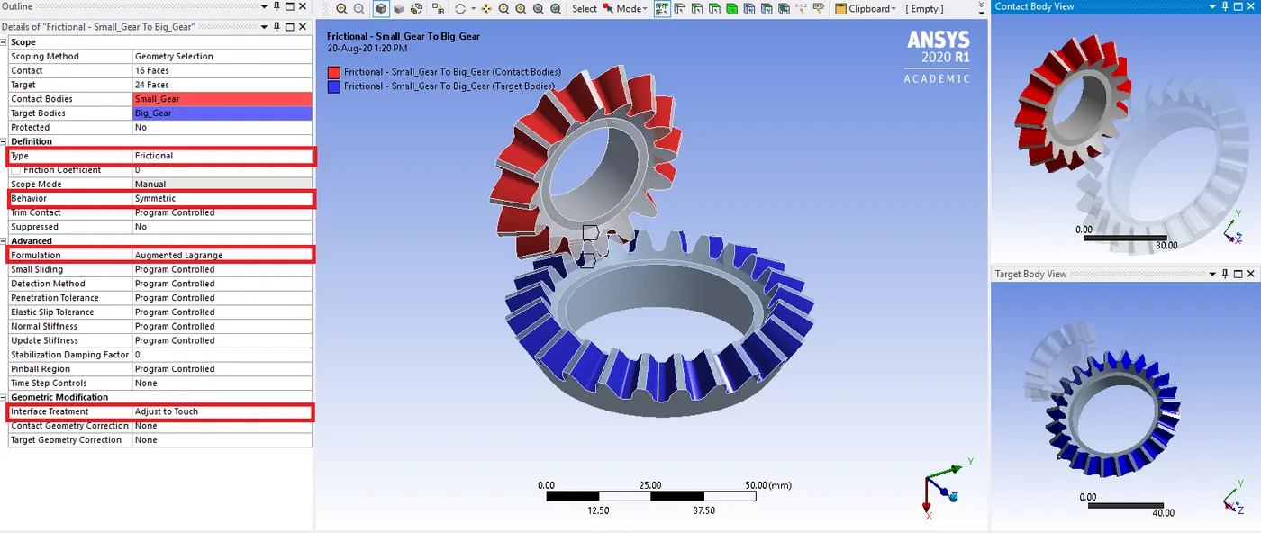
Since the bevel gear stimulation consist of two bodies coming in contact, it is important to define necessary contacts between the bodies.
The contact and target faces were defined under contact type and conditions were given below.

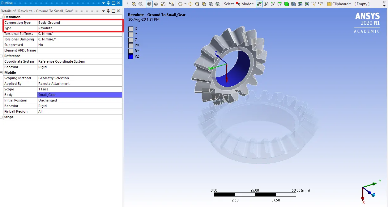
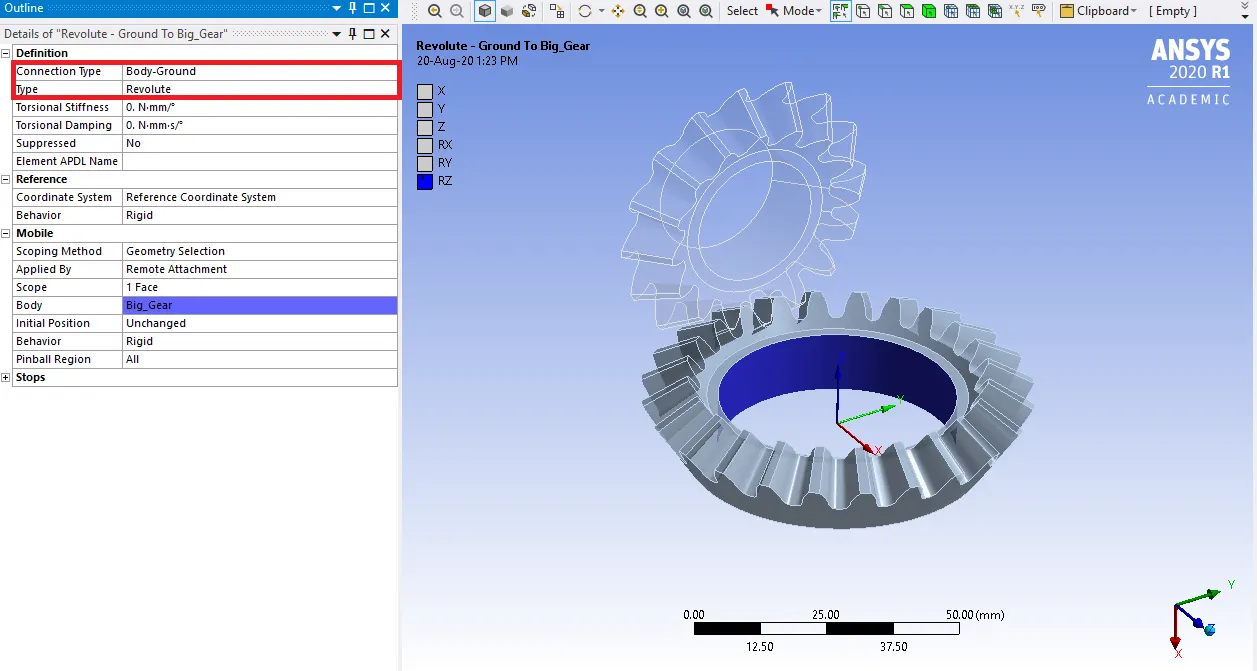
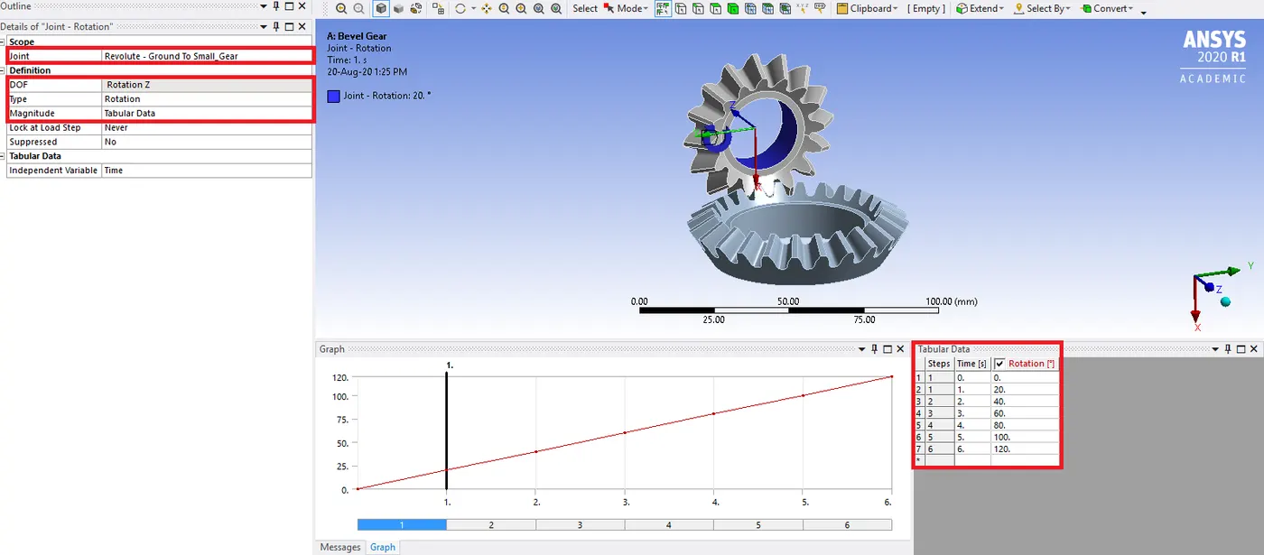
Further, joints were defined for the model. Both the gears are revolute joint and connection type is body to ground.

STEP 4) Meshing
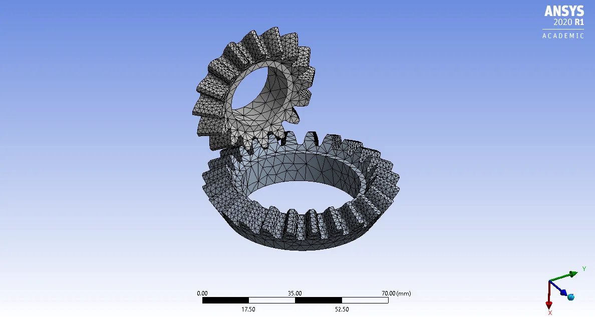
The model was meshed using ANSYS mesher. Since more focus is on the results to be obtained from the gear teeth so in those faces we have given the localized face sizing mesh. The whole model was given a mesh of element size 6mm, 5mm and 4mm and a localized mesh size of 1.75mm.

|
Mesh Size |
No. of nodes |
No. of elements |
|
6mm |
24064 |
12904 |
|
5mm |
24578 |
13272 |
|
4mm |
25199 |
13591 |
STEP 5) Boundary conditions
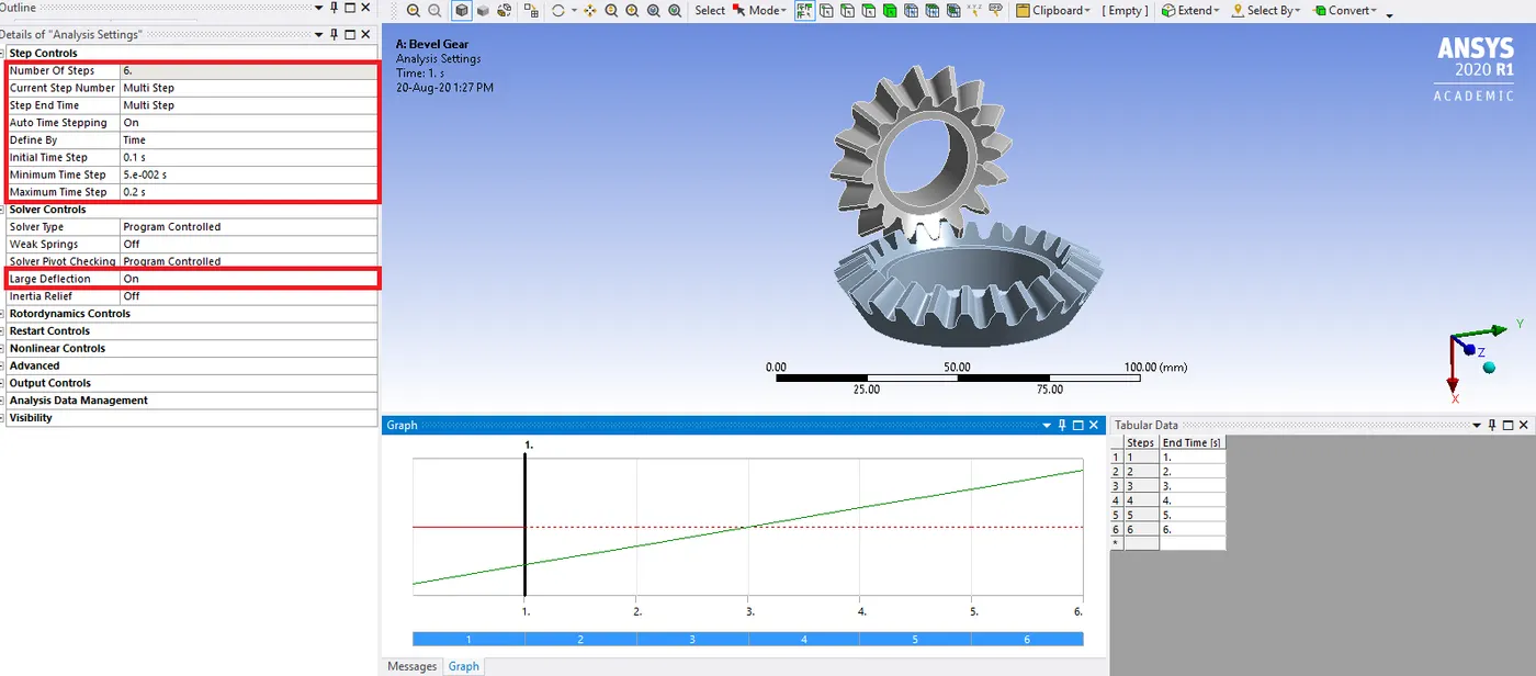
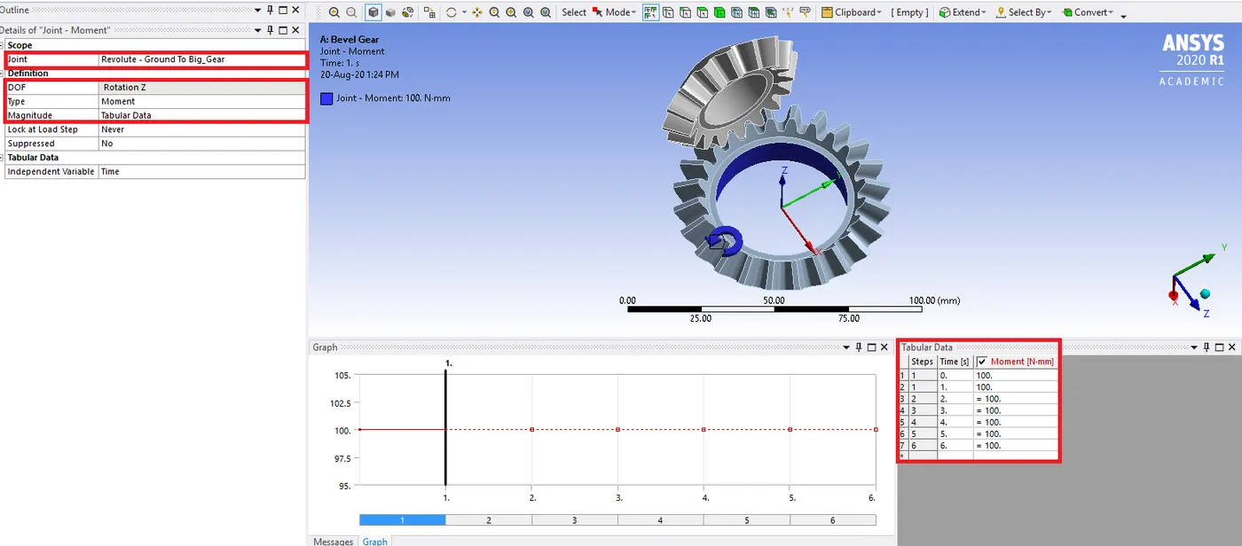
All models were subjected to the same boundary conditions as shown below.

Then joints were defined. Moment was given to the big gear of 100 N/mm. And rotation was given to the small gear of 20ᵒ in each step till 120ᵒ.

STEP 6) Results
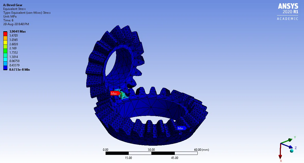
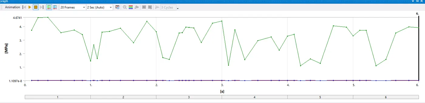
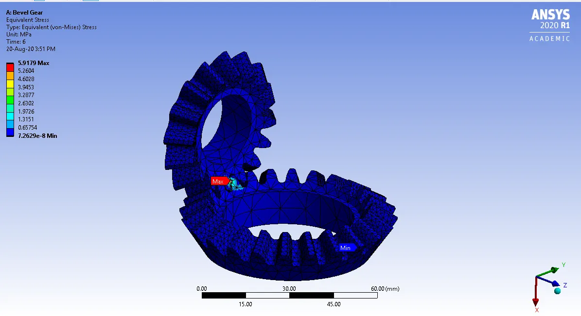
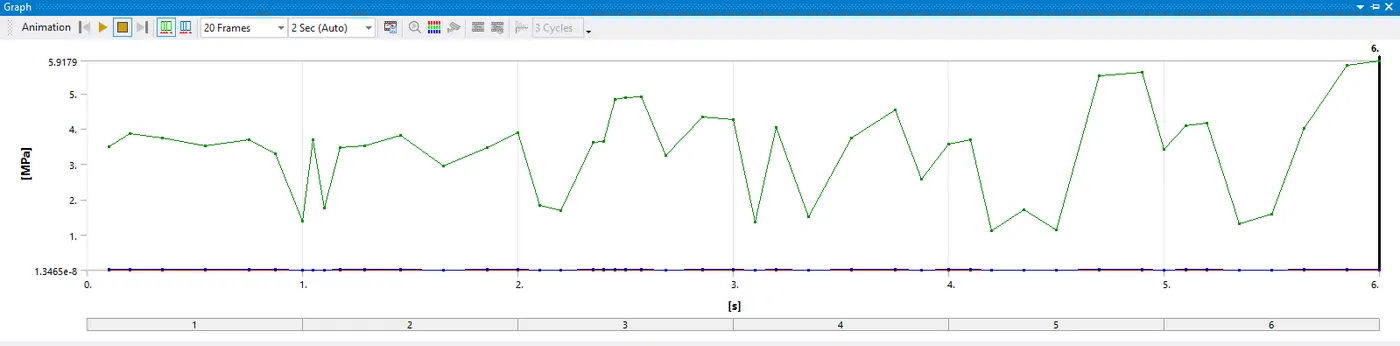
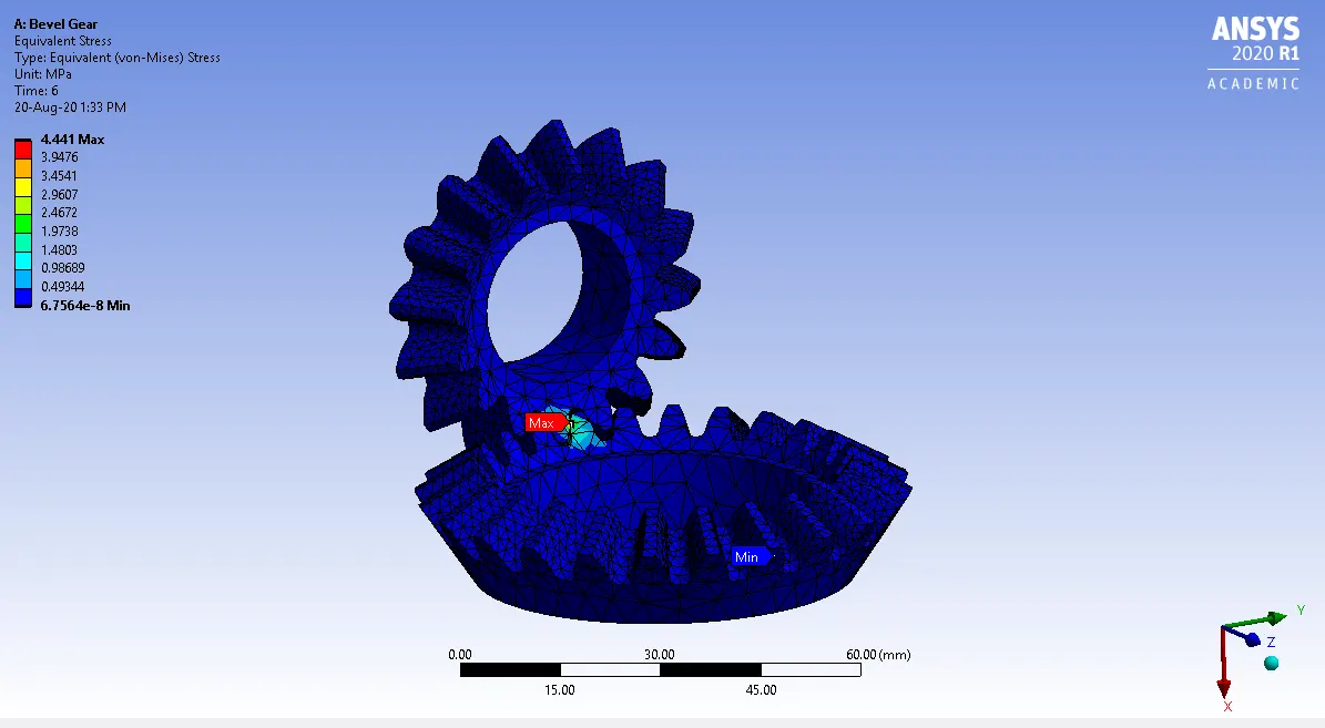
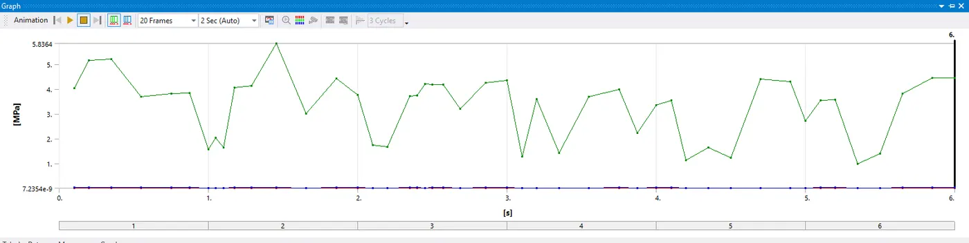
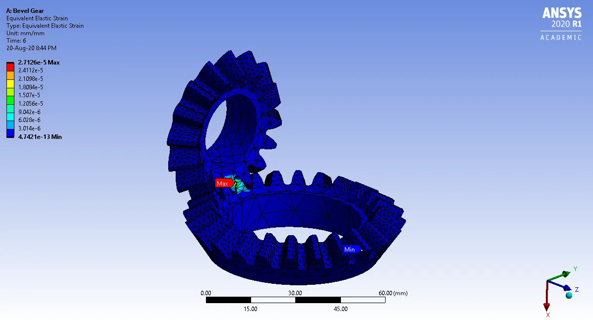
The equivalent stress, equivalent strain and total deformation were evaluated for each of the above cases.
- Equivalent stress



|
Element Size |
Maximum equivalent stress over time (MPa) |
|
6mm |
4.6741 |
|
5mm |
5.9179 |
|
4mm |
5.8364 |
- Equivalent strain
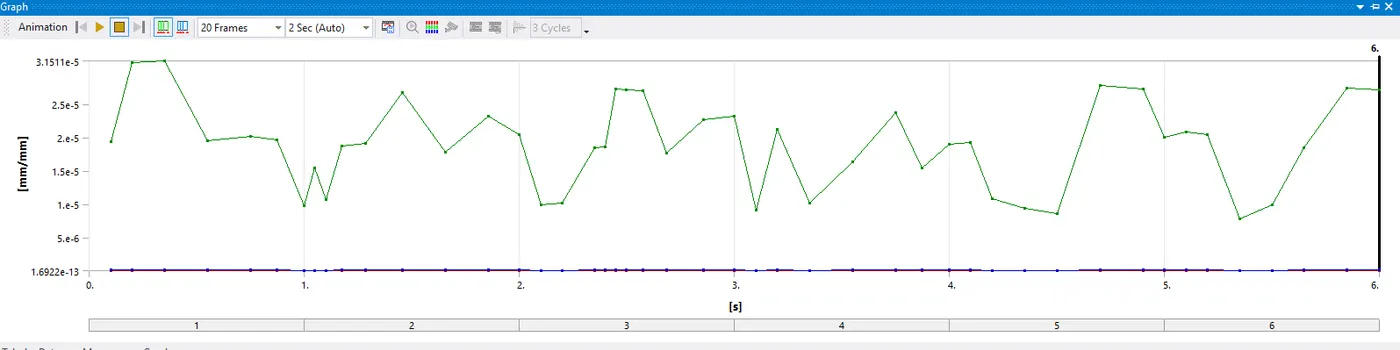
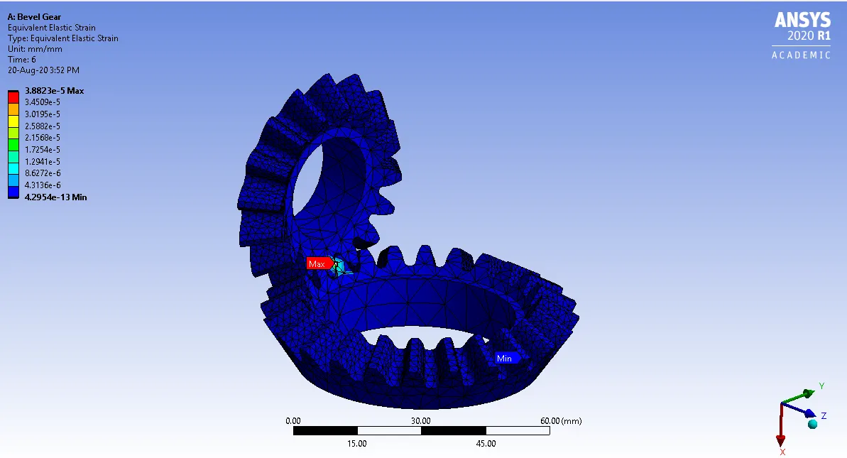
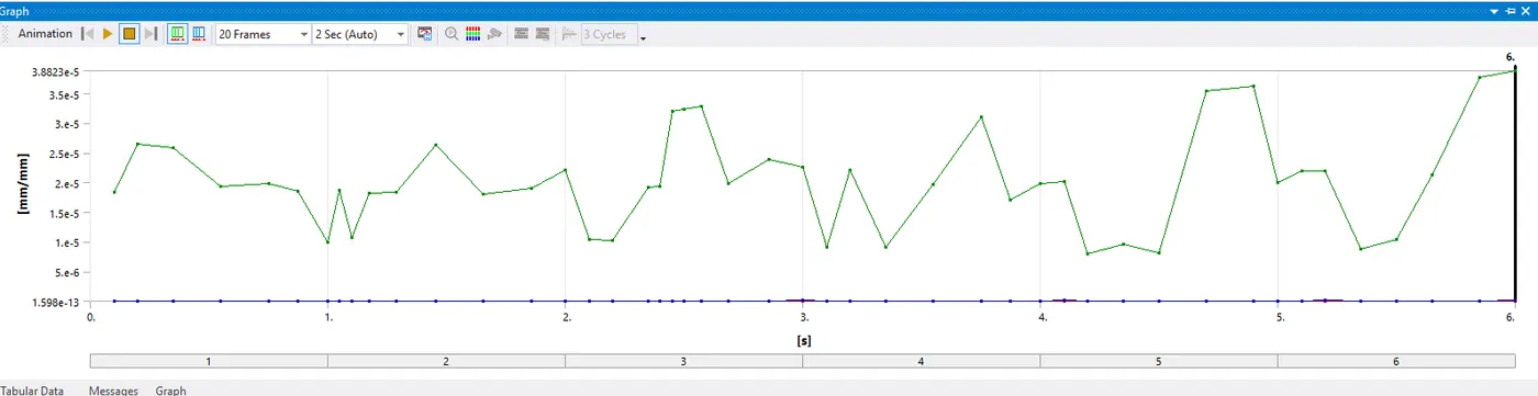
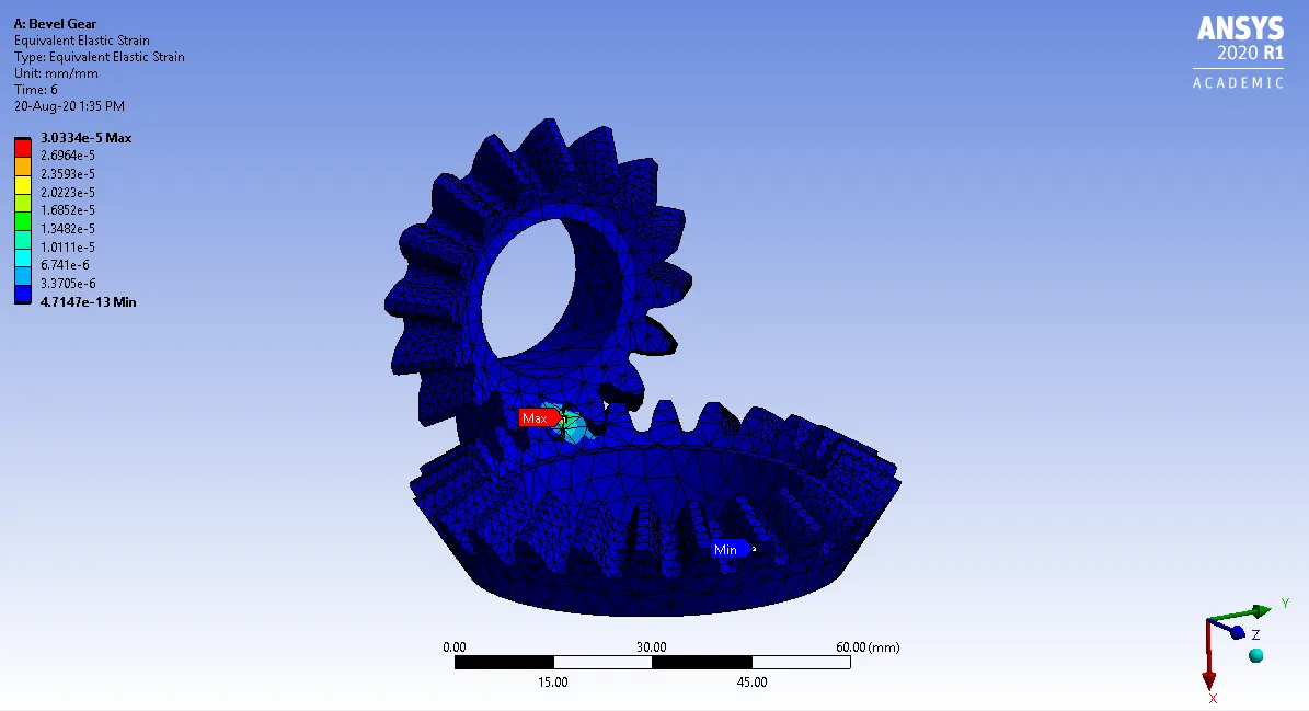
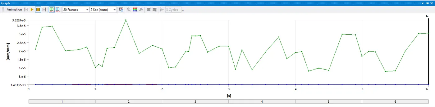
|
Element Size |
Maximum Equivalent elastic strain over time (mm/mm) |
|
6mm |
3.1511e-05 |
|
5mm |
3.8823e-05 |
|
4mm |
3.8224e-05 |
- Total deformation
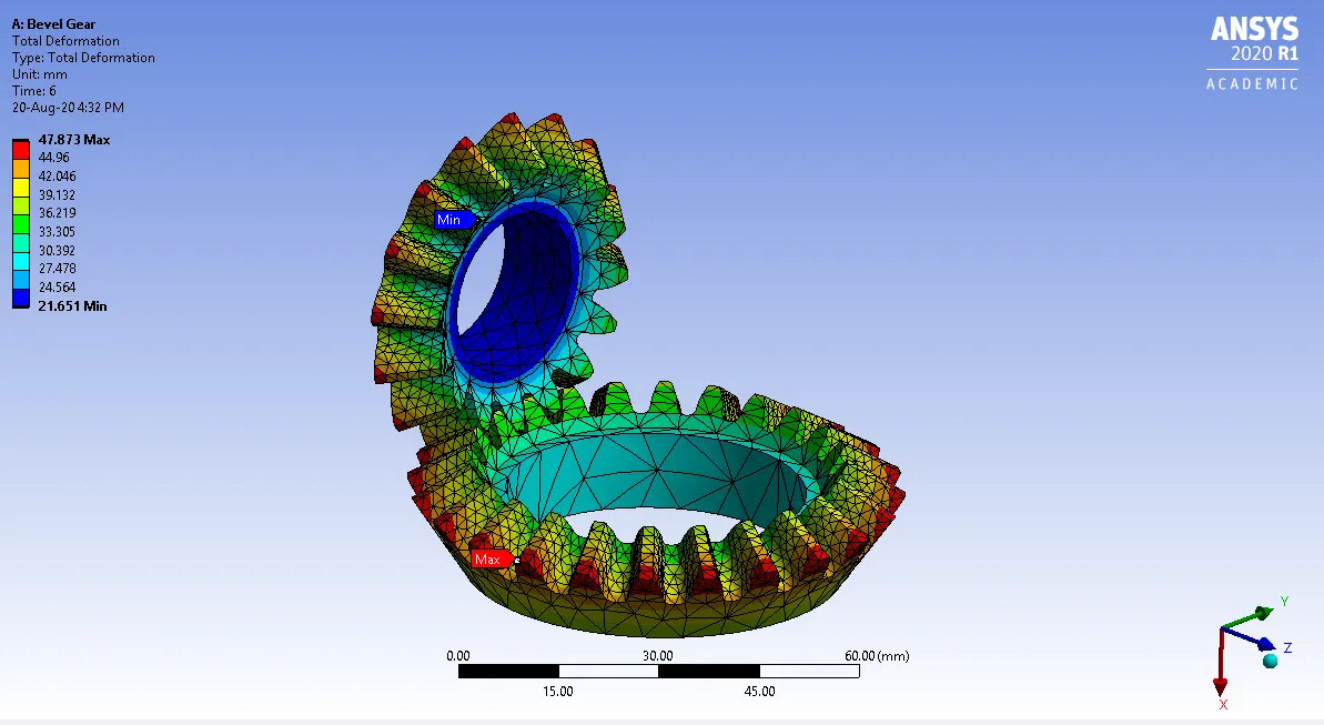
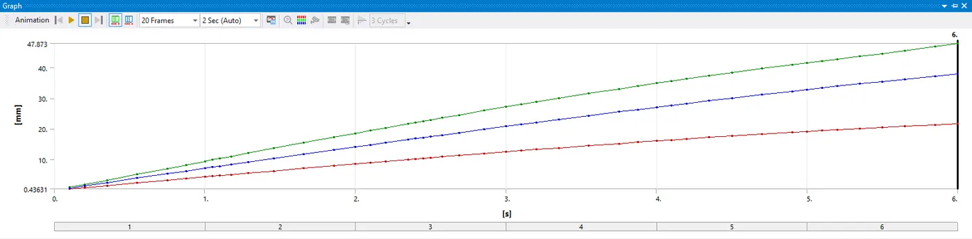
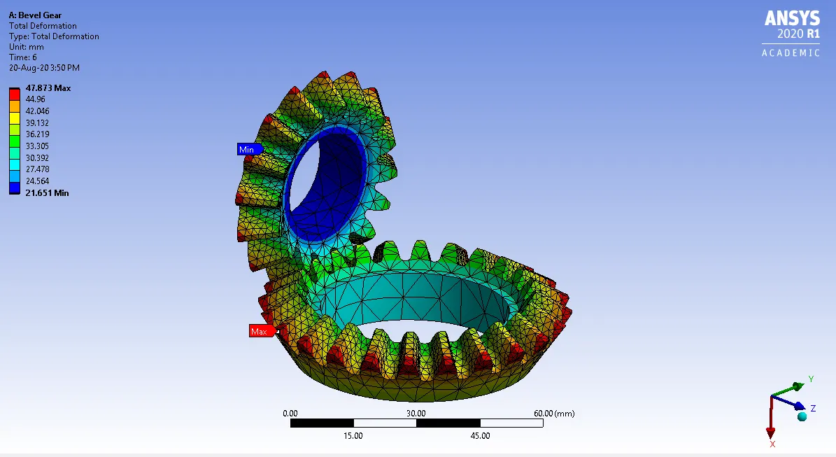
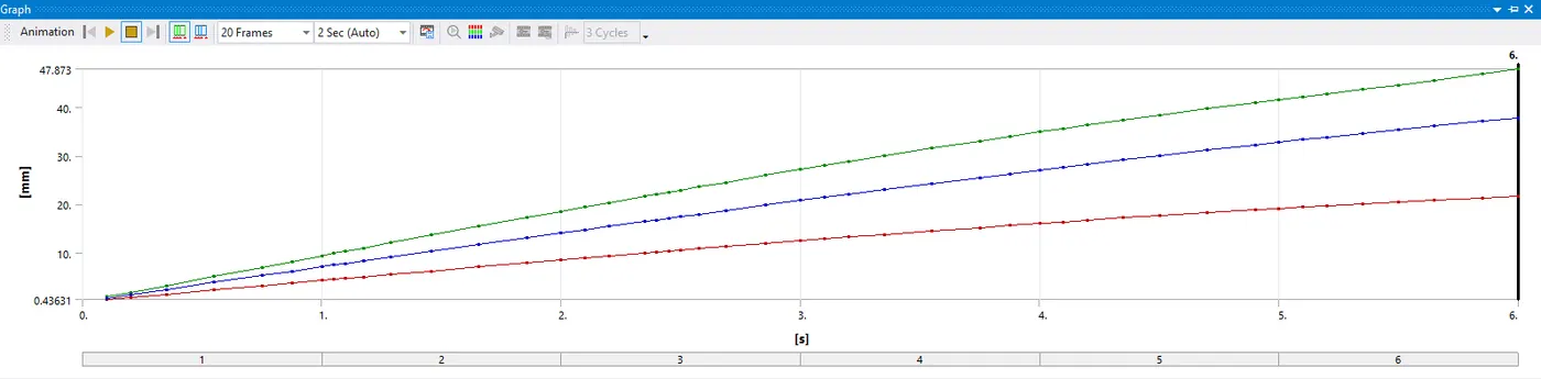
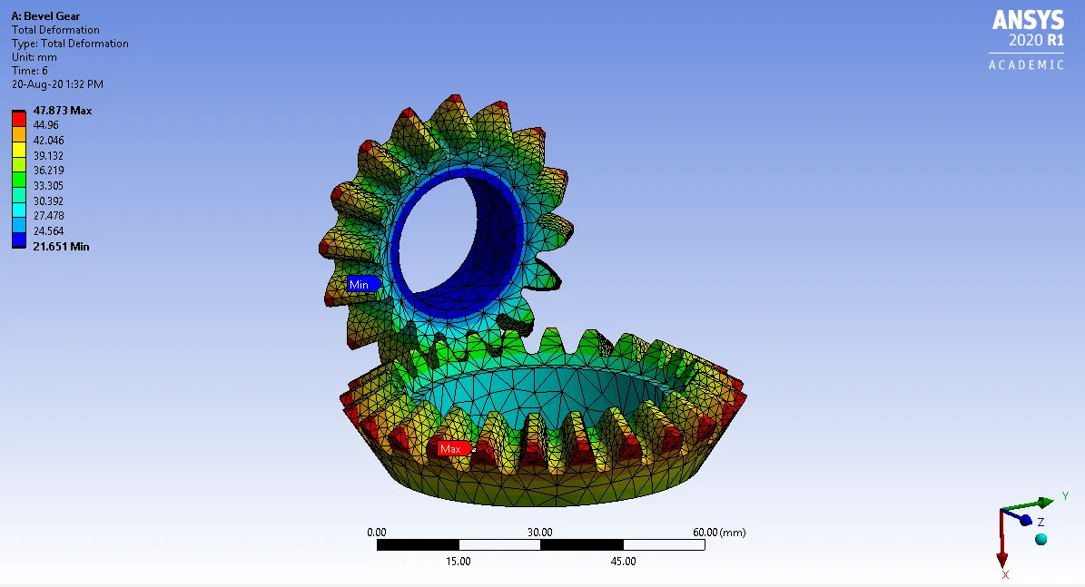
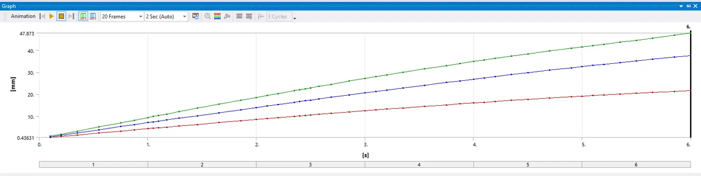
|
Element Size |
Maximum total deformation over time (mm) |
|
6mm |
47.873 |
|
5mm |
47.873 |
|
4mm |
47.873 |
CONCLUSION:
The grid dependency test performed for three cases, where global mesh size used was 6mm, 5mm and 4mm while the face sizing was kept at 1.75 mm in all cases. From the above results we get the following conclusions
|
Element size |
Equivalent stress (Max) |
%change |
Equivalent strain (Max) |
%change |
Total deformation(Max) |
|
6mm |
4.6741 MPa |
- |
3.1511e-05 mm/mm |
- |
47.873 mm |
|
5mm |
5.9179 MPa |
26.61% |
3.8823e-05 mm/mm |
23.2% |
47.873 mm |
|
4mm |
5.8364 MPa |
1.4% |
3.8224e-05 mm/mm |
1.5% |
47.873 mm |
It was found that the maximum strain and maximum stress increase considerably as the mesh size become finer. But the deformation value remains constant for all the mesh sizes. So in our academic version we cannot reduce our mesh further because for node and element constraints. A much finer mesh will help to obtain more accurate results.
So it is conclude that 4mm is not the optimum mesh size as if we refine our mesh further we may get changes in results of total deformation.
Stimulation files are attached.