Stress Concentration on a Plate with hole
OBJECTIVE: Design the model of the plate with holes with two different cases and perform the static structural analysis on both the cases to determine the maximum deformation and stress developed in the model and then compare the results.
DESIGN CONSTRAINTS:
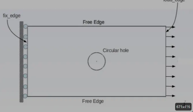
CASE 1) Plate with single hole
Dimensions: Length=300mm
Height=120mm
Thickness=30mm
Circular hole at the center: Diameter=60mm
CASE 2) Plate with three holes
Dimensions:
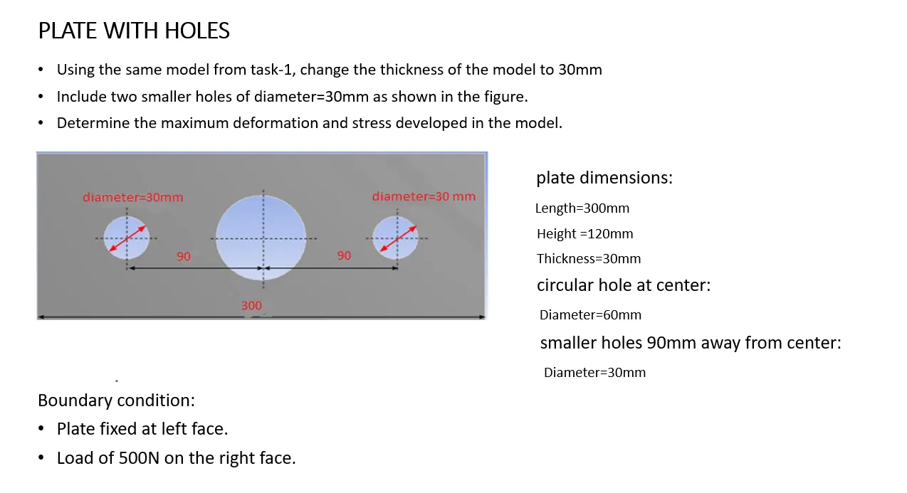
Material used: Structural Steel (in both cases)
SOLUTION:
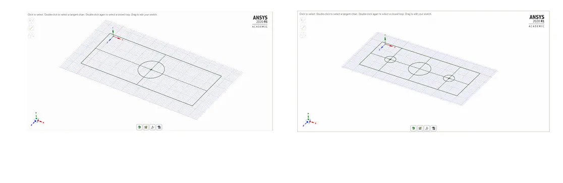
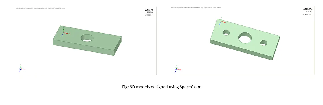
STEP 1) Plate Design
Both models are design using SpaceClaim (inbuilt ANSYS design modeler).
STEP 2) Material Assignment
Material=Structural Steel
Material Properties:
|
Properties |
Values |
|
Density |
7.85e-06 kg/mmᶾ |
|
Young’s Modulus |
2.00e+05 MPa |
|
Poisson’s Ratio |
0.3 |
|
Bulk Modulus |
1.67e+05 MPa |
|
Shear Modulus |
76923 MPa |
|
Isotropic Secant Coefficient of Thermal Expansion |
1.20e-05 1/ᵒC |
|
Compressive Ultimate Strength |
0 MPa |
|
Compressive Yield Strength |
250 MPa |
|
Tensile Ultimate Strength |
460 MPa |
|
Tensile Yield Strength |
250 MPa |
|
Isotropic Thermal Conductivity |
0.0605 W/mm.ᵒC |
|
Specific Heat Constant Pressure |
4.34e+05 mJ/kg.ᵒC |
|
Isotropic Resistivity |
0.00017 ohm-mm |
|
Isotropic Relative Permeability |
10000 |
STEP 3) Meshing
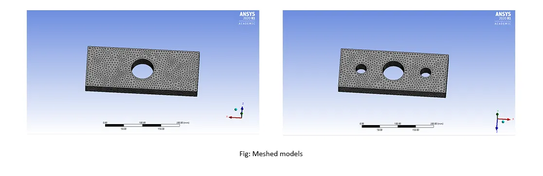
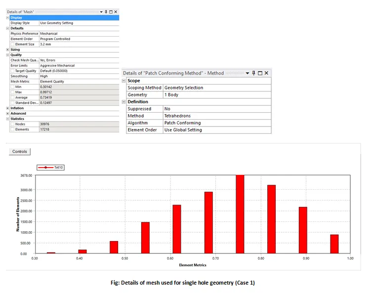
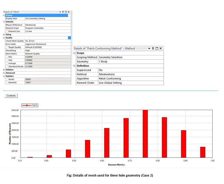
The models are meshed using ANSYS mesher. An element size of 3.2mm is used in case 1 and an element size of 3.5mm is used in case 2. In both the models the elements are tetragonal in shape and the meshing is carried out using patch conforming algorithm.
From mesh metric we can see the element quality for both the models. In the case 1 an average element quality of 0.734 was achieved and in the case 2 an average element quality of 0.734 was achieved.
STEP 4) Assigning boundary conditions
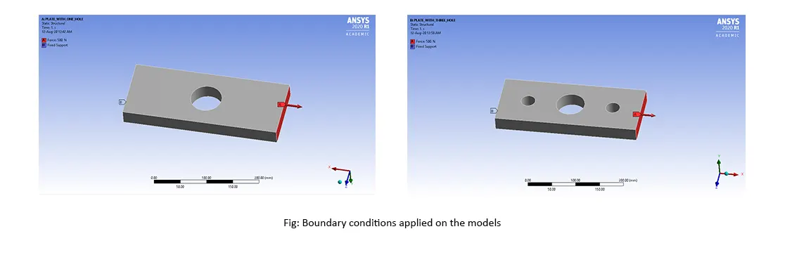
Both the models were given the same boundary conditions, with one of the face is fixed and the other was given a force of 500N.
STEP 5) Results
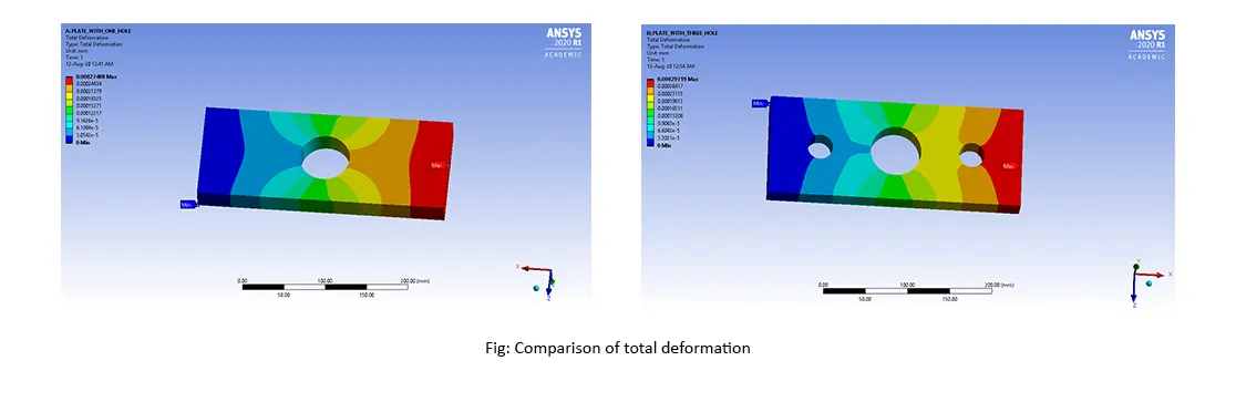
- Total deformation
|
Cases |
Maximum Deformation |
Average Deformation |
|
Plate with single hole |
2.7488e-004 mm |
1.3905e-004 mm |
|
Plate with three holes |
2.9719e-004 mm |
1.4476e-004 mm |
- Maximum stress developed
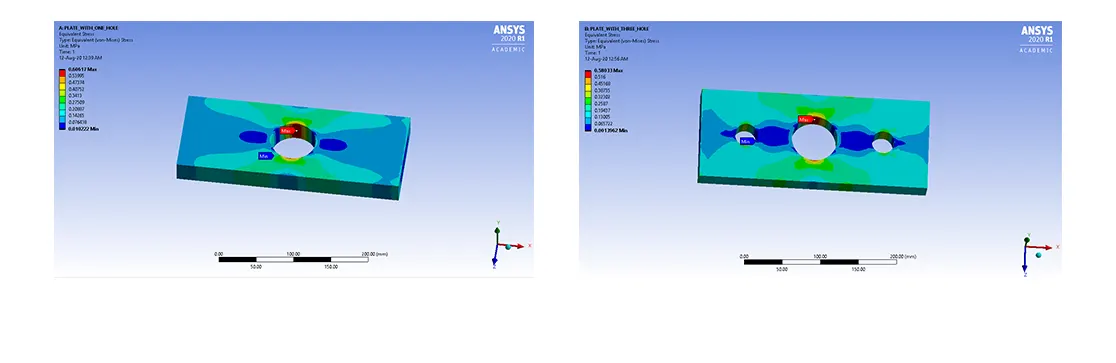
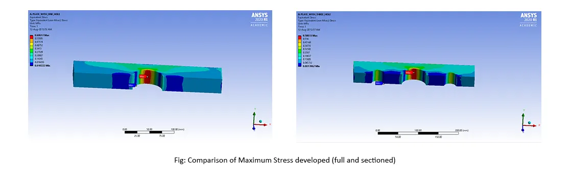
The equivalent Von-Mises stress was evaluated for both the cases.
|
Cases |
Maximum Stress |
Average Stress |
Minimum Stress |
|
Plate with single hole |
0.60617 MPa |
0.17019 MPa |
1.0222e-002 MPa |
|
Plate with three holes |
0.58033 MPa |
0.17142 MPa |
1.3962e-003 MPa |
CONCLUSIONS:
From the above results the following conclusions can be inferred.
Comparison of maximum deformation and stress.
- When maximum deformation is compared for both the cases then we can see that in case 2 the deformation is slightly more than in case 1. The difference between in maximum deformation and average deformation is 0.2231e-004 mm and 0.0571e-004 mm respectively. Hence, we can conclude that deformation behavior is almost same for both the cases.
- When the stresses are compared for both the cases then we can see that maximum stress is higher in case 1 as compare to case 2. The difference in the maximum value and average value is 0.02584 MPa and 0.00123 MPa respectively.
From the above analysis we can see that the stresses developed in case 1 are higher as compared to the case 2, which means the chances of failure is higher in case 1. Hence from an analysis point of view, case 2 is more preferable than case 1.
From the manufacturing point of view, we can see that the geometry of case 2 is more complicated and has more features than case 1 geometry. So this can led to more amount of machining and man power to fabricate it, which will led to increase in cost of the product. As from above point we can see that there is no much difference between the stresses developed in both the cases. So we can considered that from manufacturing point of view case 1 is better choice.