Week 5 Bending of iPhone
AIM:
To simulate the bending of iPhone for their total deformation,stress and strain using ansys workbench.
OBJECTIVES:
-
Case 1: Simulate the model as it is given in the video
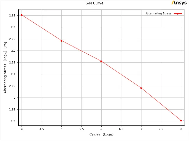
Case 2: Move the bottom fingers from their defined position to the given position X= 22.5mm & Z= 10mm and obtain the results for the simulation. Also define the S-N curve for the Aluminium Alloy material as per values given below and determine the fatigue life results for the same.
Stress, MPa Number of Cycles, N 225 10000 175 100000 143 1000000 110 10000000 80 100000000 Results and Deliverables
- Obtain the directional deformation for the model
- Factor of Aluminium Alloy NL
- Life of the Aluminium alloy for the case
- Compare the results and present with the conclusion.
PROCEDURES:
- Drop the static structural from the analysis settings.
- Allocate the required material from the engineering data.
- Then import the geometry, make some changes,then open the model.
Materials:
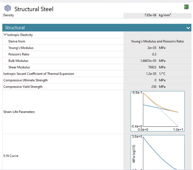
Structural steel
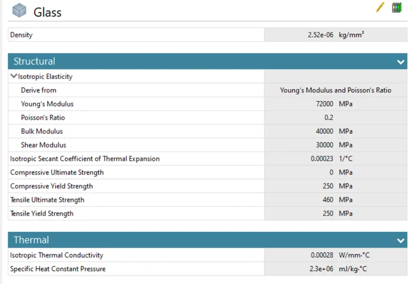
Glass
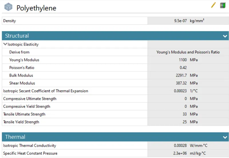
Polyethylene
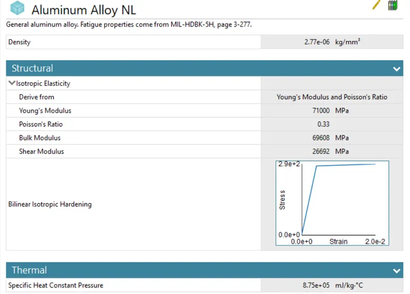
Aluminium Alloy
Geometry:
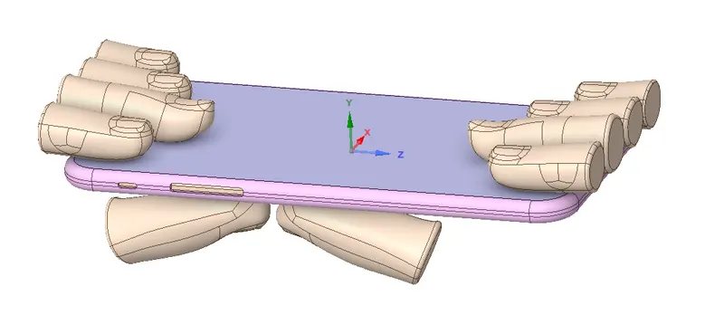 |
- First change the default name to FRAME,DISPLAY,INSIDE,PUSHING FINGERS & FINGERS.
- Assign the selected material for
FRAME = ALUMINIUM ALLOY
DISPLAY, = GLASS
INSIDE, = POLYETHYLENE
PUSHING FINGRES = STRUCTURAL STEEL
FINGRES = STRUCTURAL STEEL
- Slecet the all fingures and make stiffness behavior is rigid.
Connections
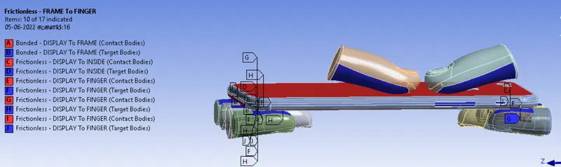
- Select all contact and right click on rename based on definition.
- Then unselect to DISPLAY TO FRAME,remaning contacts are frictionless, because DISPLAY TO FRAME is bonded.
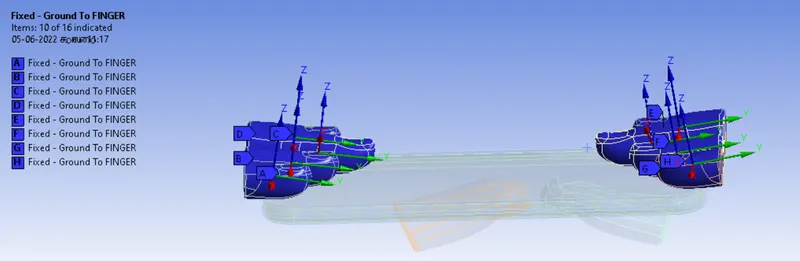
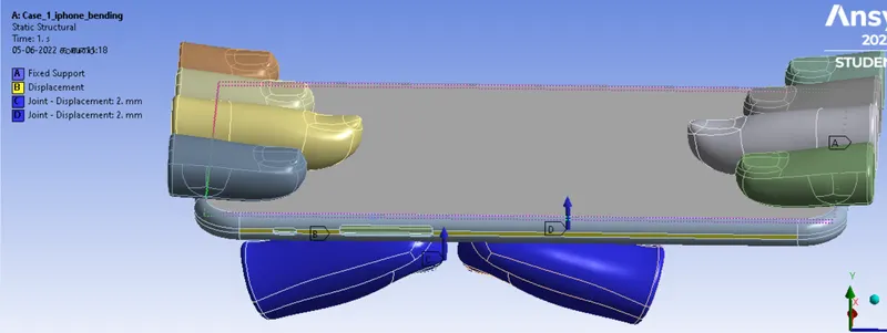
- Now to create body to ground fixed joints for all fingers, Select the finger and, hide all other bodies. Now select the finger, use box selector then apply.
- simillarly this procces for all other frictionless fingers.
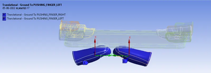
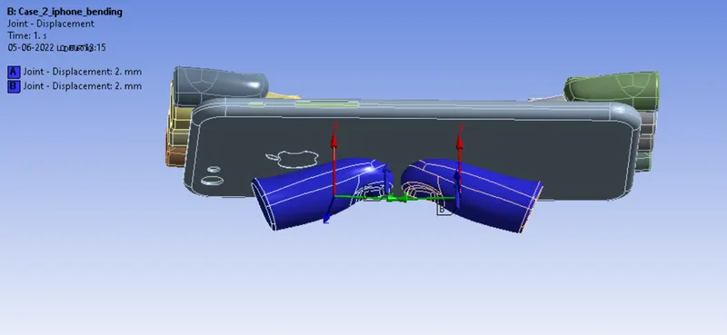
- Now create body to ground translational joints for pushing fingers, the same process applies to what we do for a fixed joint.
Mesh:
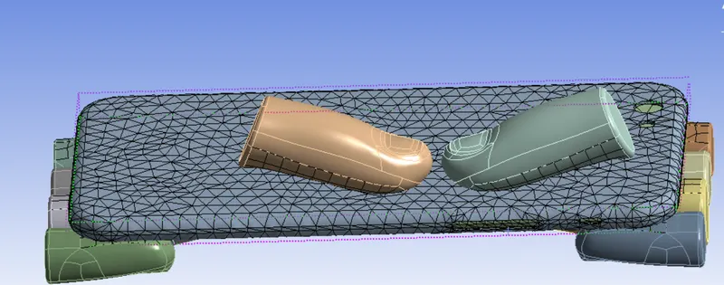
- Now open the mesh, insert the sizing
- Select the back side of the iphone and pushing fingers and generate a mesh.
Boundary conditions:
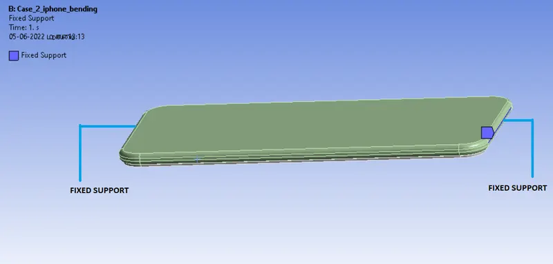
- Now static structural, insert the fixed support and select the inside and apply.
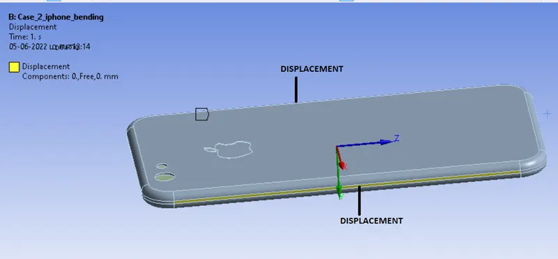
- Insert the displacement load, select a up and down side of the frame.
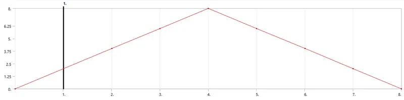
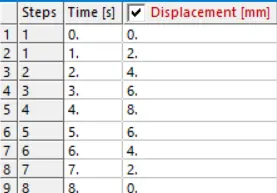
- insert the joint load, joint is translational - ground to pusing finger, type is displacement,magnitude is tabular data.
- Simillarly same procedure for the next pushing finger.
Total No.of. Steps =8
Slover type = Direct
Large Deflection = ON
Weak spring = Program controlled
Stabilization = constant
Energy dissipation ratio = 0.1
Activation for the first substep = yes
Output controlls = Make all outputs yes
Soluitions:
- After giving proper boundary conditions,create desired solutions for output results,create solutions for Directional deformation, stress and strain. slove evaluate for solutions.
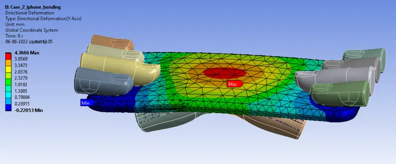
- Obtain the directional deformation for the model
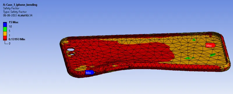
- Factor of Aluminium Alloy NL
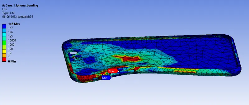
- Life of the Aluminium alloy for the case
RESULTS:
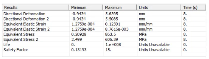
case_1
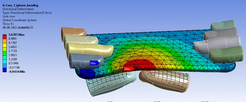
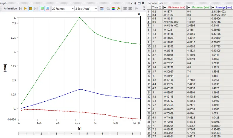
Directional deformation of full body and graph
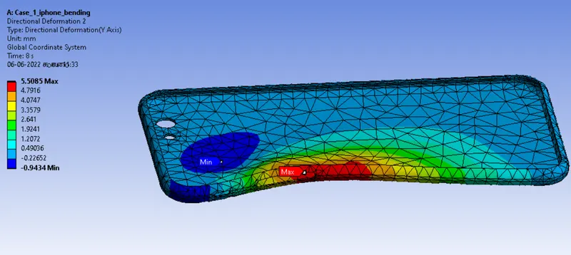
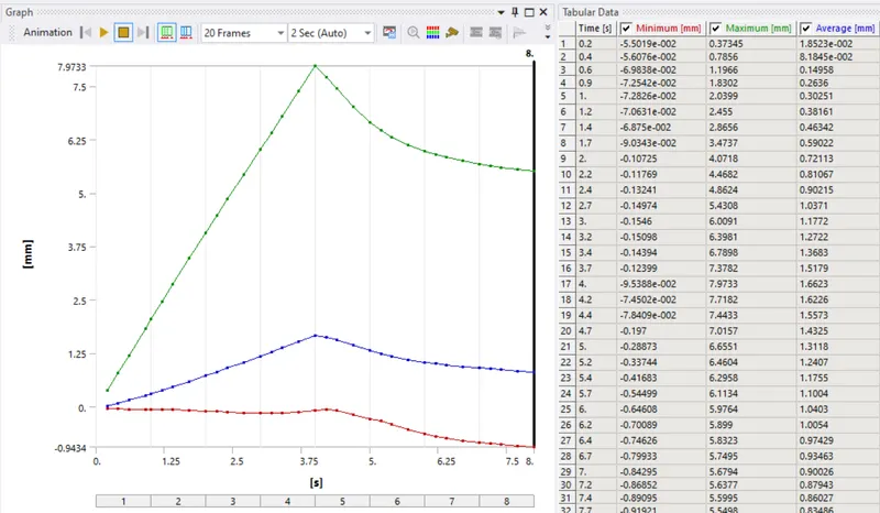
Directional deformation of frame and graph
Equivalent Elastic strain and graph
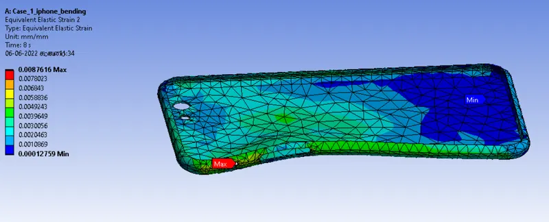
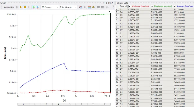
Equivalent stress and graph
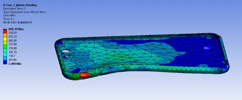
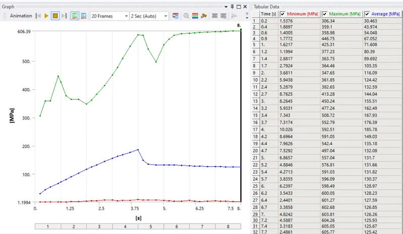
Safety factor
Life
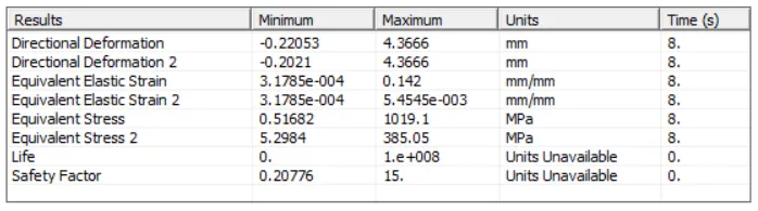
case_2
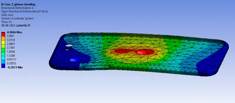
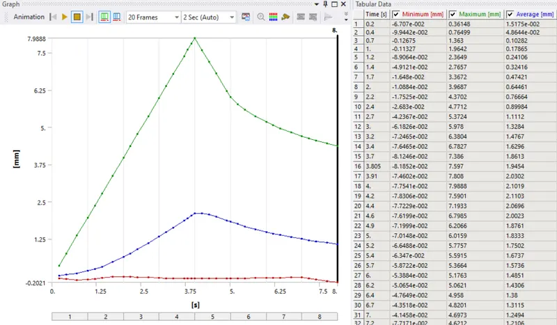
Directional deformation of full body and graph
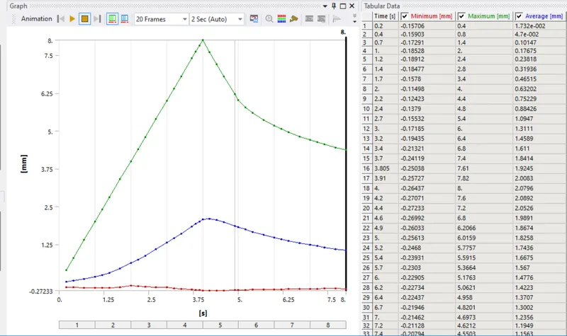
Directional deformation of frame and graph
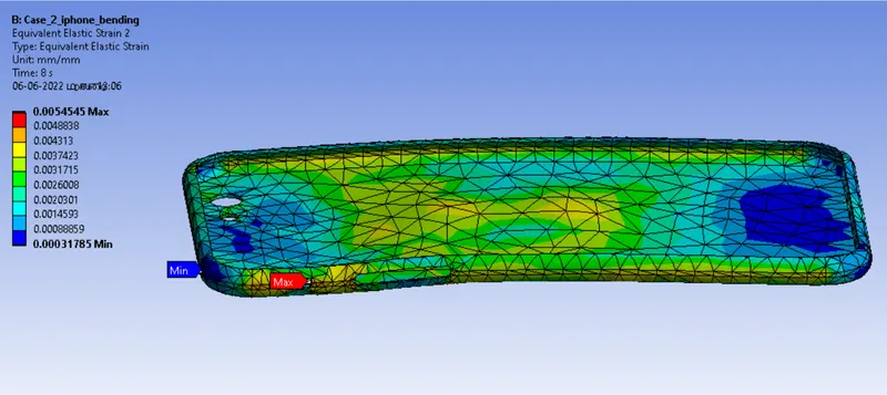
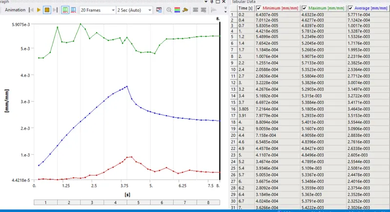
Equivalent Elastic strain and graph
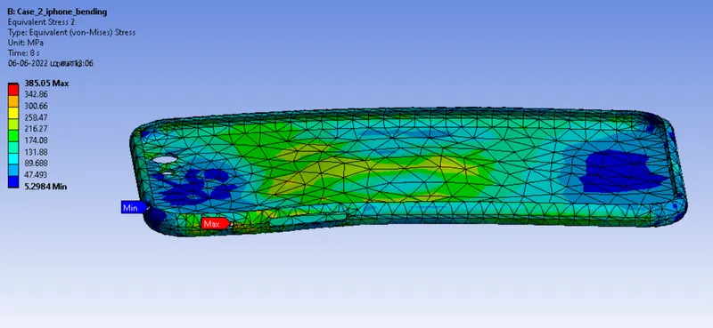
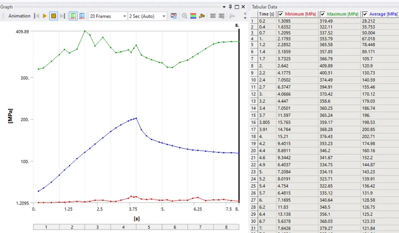
Equivalent stress and graph
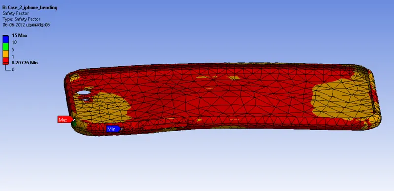
Safety factor
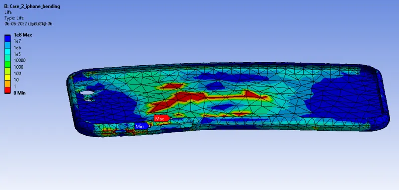
Life
RESULTS:
CASE_1
CASE_2
CONCLUSIONS:
- Simulation of bending process of i phone carried out using Ansys workbench. From the analysis, it is found that the application of displacement load at diffrent location produces plastic deformation in the Aluminum Alloy Frame. As the point of load application is at different locations, effect of the deformation is different in both cases. The Aluminium Alloy Frame is not able to the 8mm bending load.
SIMULATION LINK:
https://drive.google.com/file/d/1mGVmt4Ugcr9uywySsnFtnEwZhhymqGYk/view?usp=sharing