Week 5 Bending of iPhone
Aim: To perform the bending of the iPhone and obtain the fatigue life of the Material.
Objective:
Case 1: Simulation of the model as it is given in the video.
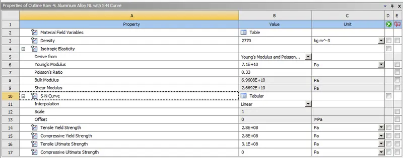
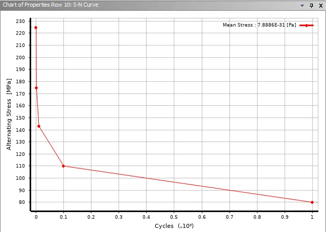
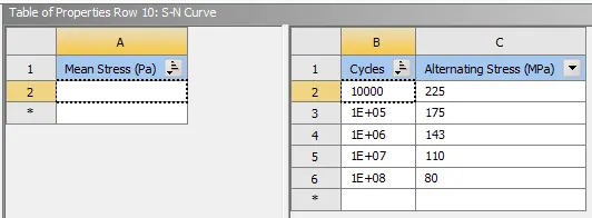
Case 2: Move the bottom fingers from their defined position to the given position X= 22.5mm & Z= 10mm and obtain the results for the simulation. Also, define the S-N curve for the Aluminium Alloy material as per the values given below and determine the fatigue life results for the same.
| Stress, MPa | Number of Cycles, N |
| 225 | 10000 |
| 175 | 100000 |
| 143 | 1000000 |
| 110 | 10000000 |
| 80 | 100000000 |
- Obtain the directional deformation for the model
- The factor of Aluminium Alloy NL
- Life of the Aluminium alloy for the case
- Compare the results and present the conclusion.
Introduction:
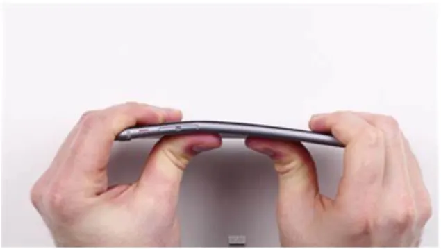
There is a number of reports claiming that the iPhone bends inside of people's pocket. Some speculate that the tightness of your pants is significant here. The tighter they are, the more pressure they exert on your phone. it seems clear, too, that a lot depends on whether you lean forward when you sit or maintain a more correct upright position.
- You'd imagine that you'd be able to feel your bones or the chiselled tautness of your thigh muscles beginning to crush your phone. perhaps, though, you're so engrossed in your work that you don't sense what you're doing to your status symbol until it's too late.
- So, to check the possibilities of the bending and how it bending and how it bends on applying the load at a different location from the backside, we have to do some analysis on it. We will do the analysis by pushing the backside of the iPhone with Pushing fingers while other fingers will hold it from the topside.
Procedure:
1) For iPhone bending analysis, we use the static structural tools in the analysis system toolbox to define the geometry and other input parameters.
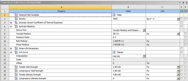
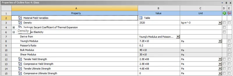
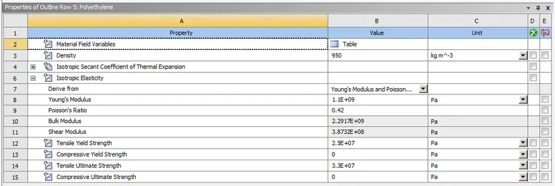
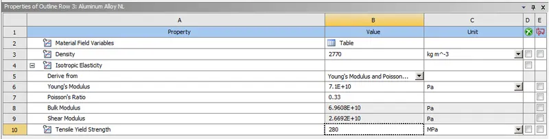
2) In the engineering data we input the material and its properties. In this case, we are using Structural Steel, Glass, Polyethylene, Aluminium of non-linear material and Aluminium Alloy with an S-N curve and its properties are shown below.
3) Verifying the geometry of the figure.
Case 1:
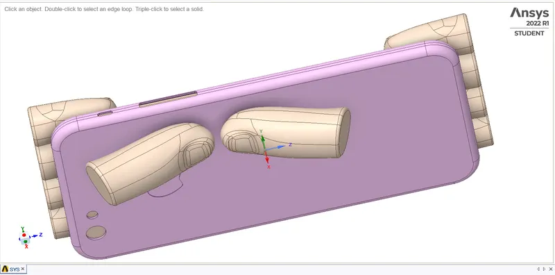
Case 2: The pushing fingers are moved along the X-axis of 22.5 mm and the Z-axis of 10mm.
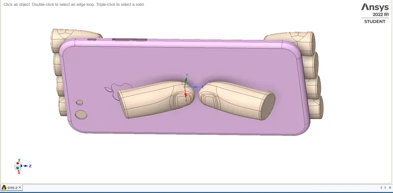
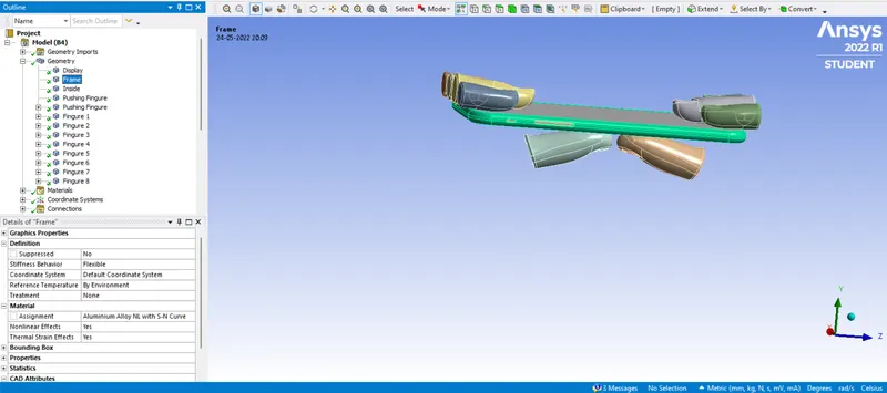
4) In the geometry of the model,
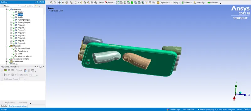
Case 1: The Display is made up of Glass, the Frame is made up of Aluminium Alloy NL and all fingers are made up of Structural Steel metal.
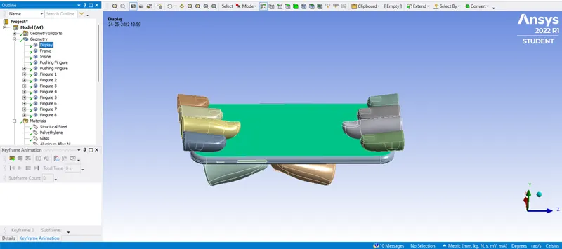
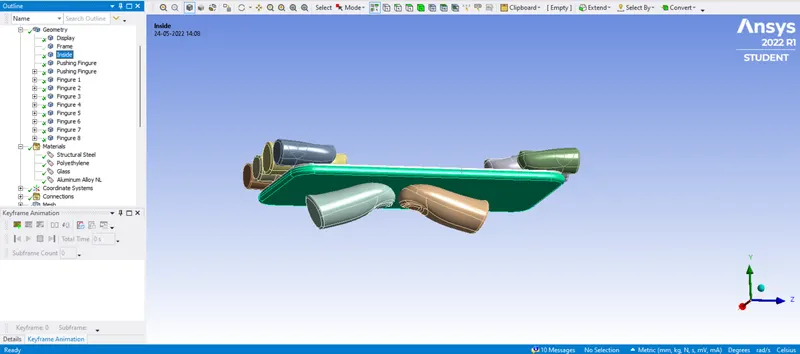
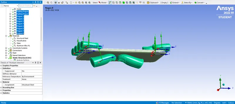
Behaviour is taken as Rigid.
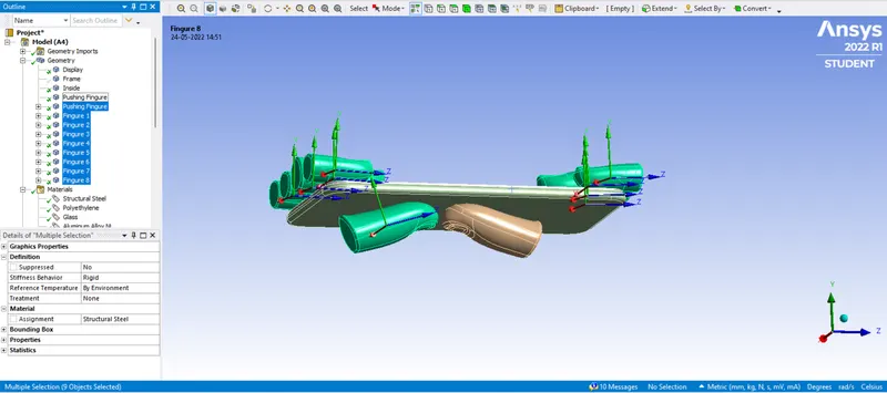
Behaviour is taken as Flexible.
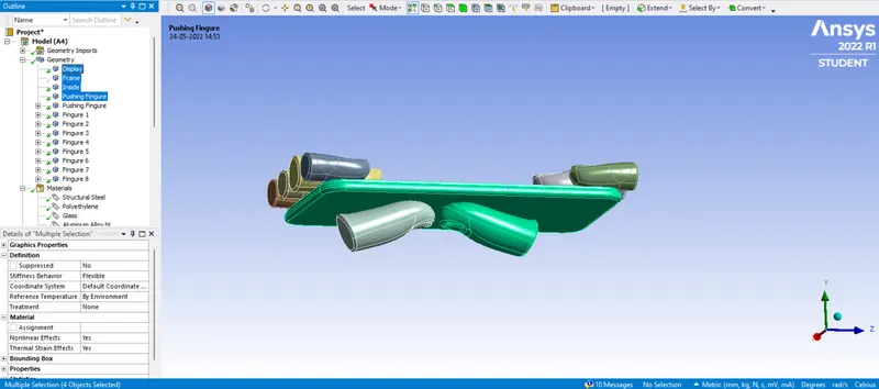
Case 2: The Display is made up of Glass, the Frame is made up of Aluminium Alloy with an S-N curve updated and all fingers are made up of Structural Steel metal.
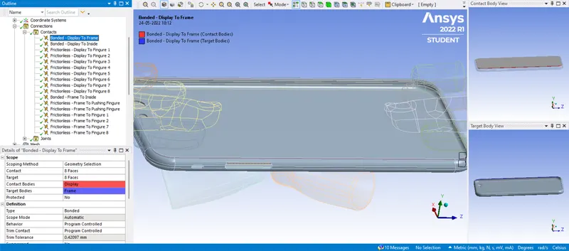
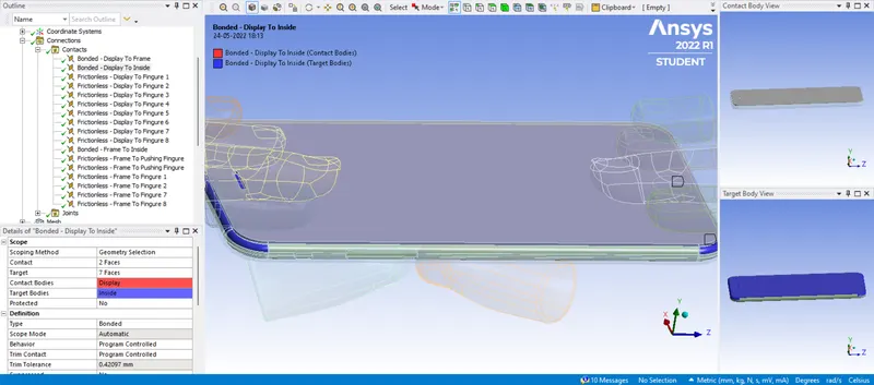
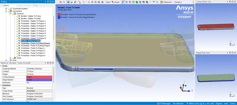
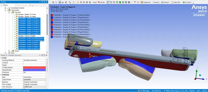
5) In connection, we have to define the contact faces of the geometry by selecting and deselecting contact or target bodies. In contacts under the connection tab, we define the type of contact as frictionless and bonded contacts wherever it is necessary.
6) Defining Joints for the geometry,
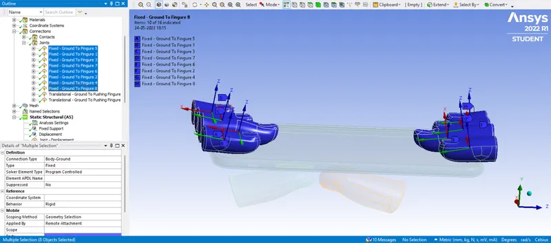
Fingers for the model are connected as given Connection Type as Body-Grounded and Type as Fixed.
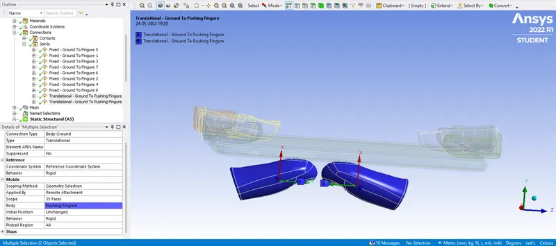
Pushing Fingers for the model are connected as given Connection Type as Body-Grounded and Type as Translational.
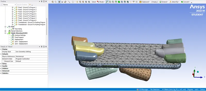
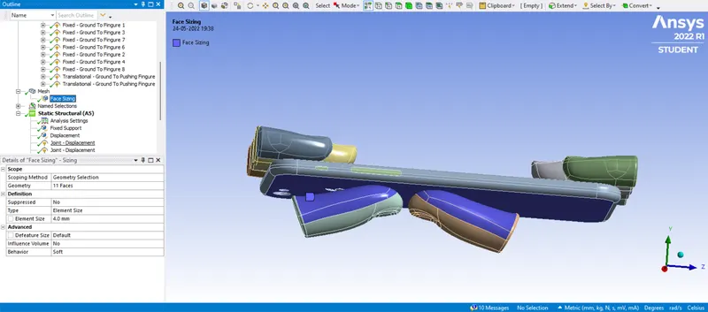
7) By opening the modelling tab, we mesh the geometry with element size as default and finer mesh size where contacts are present. Generating the mesh thereafter by right-clicking on the Mesh icon. Finer mesh is used for the sheet that will get deformed and wherever the sheet comes in contact.
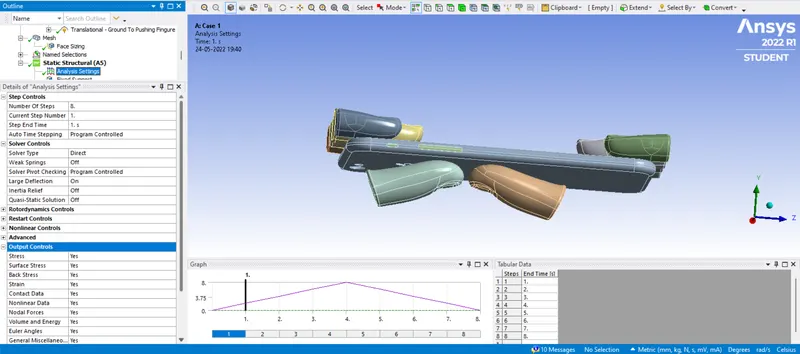
8) We open the analysis setting where we define the Displacement and Fixed Supports for 8-steps
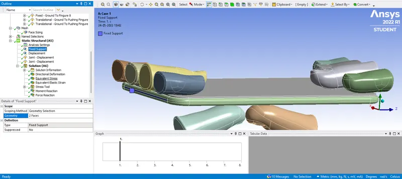
Fixed Support: We select the top and bottom of the inside for fix support.
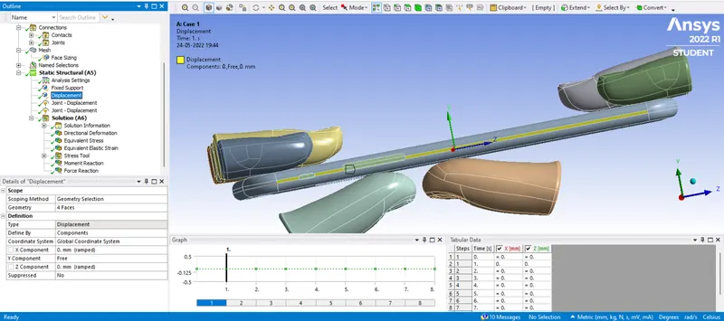
Displacement: Both sides of the frame are selected for displacement on Y-axis and making the X and Z-axis constant.
Joint-Displacement: Joint-Displacement for pushing fingers are moved in Y-direction as it presses Frame up to 8 mm. The values given are 2, 4, 6, 8, 6, 4, 2 and 0.
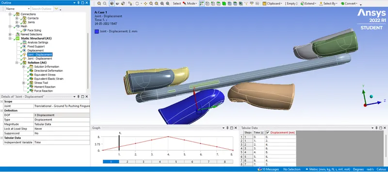
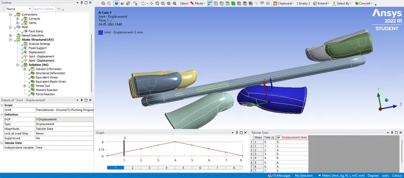
9) The solutions obtained are shown below
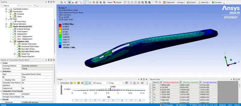
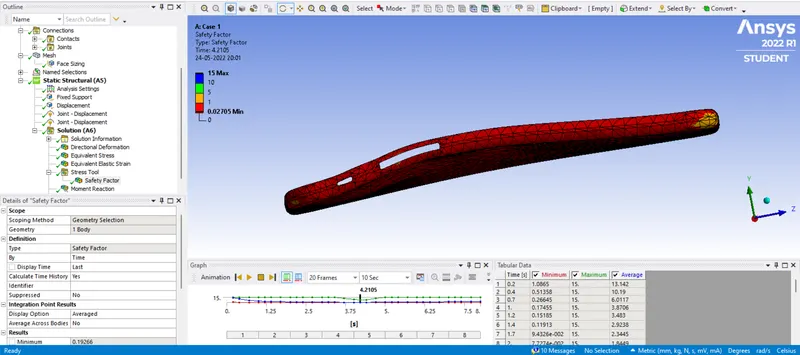
Case 1: As per the Video
Equivalent Stress of the Frame:
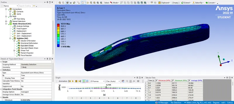
Directional Deformation in Y-axis of the Frame:
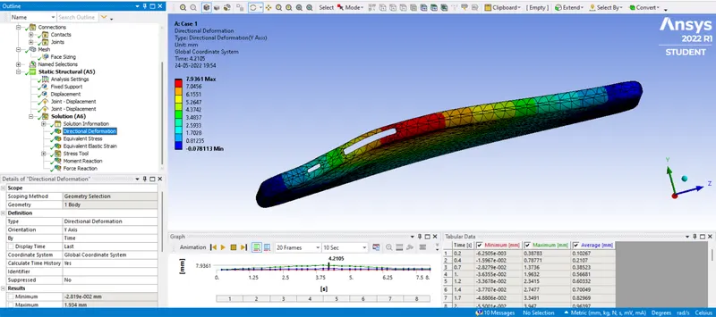
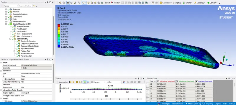
Equivalent Elastic Strain of the Frame:
Safety Factor of the Frame:
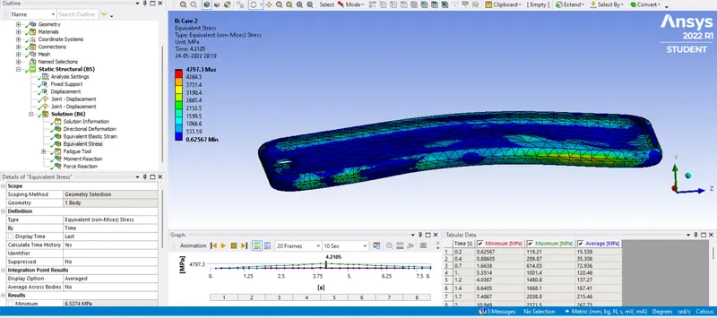
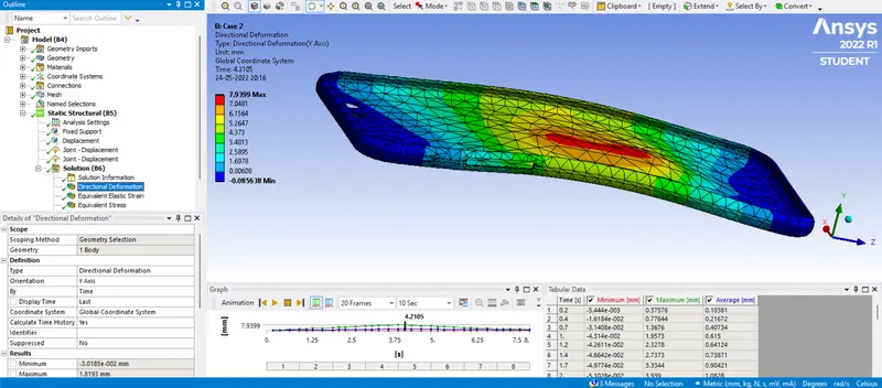
Case 2: As per the given details
Equivalent Stress of the Frame:
Directional Deformation in Y-axis of the Frame:
Equivalent Elastic Strain of the Frame:
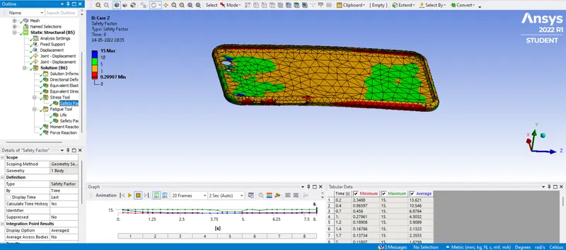
Safety Factor of the Frame for Stress Tool:
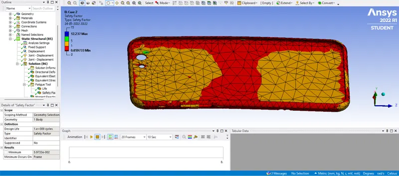
Safety Factor of the Frame for Fatigue Tool:
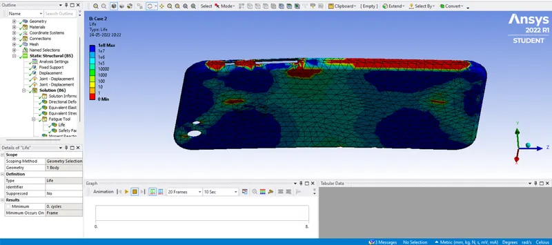
Life of the Frame for Fatigue Tool:
Result:
| Materials | Case 1 | Case 2 |
| Equivalent Elastic Strain for Frame (Maximum) in mm/mm | 2.5764e-002 | 2.3697e-002 |
| Equivalent Elastic Strain for Frame (Minimum) in mm/mm | 1.9266e-004 | 3.7003e-004 |
| Directional Deformation in Y-axis(Maximum) in mm | 1.934 | 1.8193 |
| Directional Deformation in Y-axis(Minimum) in mm | -2.819e-002 | -3.0185e-002 |
| Equivalent Stress for Frame (Maximum) in MPa | 1453.3 | 1339.3 |
| Equivalent Stress for Frame (Minimum) in MPa | 8.2024 | 6.5374 |
| Safety Factor of Stress Tool for Frame (Maximum) | 15 | 15 |
| Safety Factor of Stress Tool for Frame (Minimum) | 0.19266 | 0.20907 |
| Safety Factor of Fatigue Tool for Frame (Maximum) | --- | 12.237 |
| Safety Factor of Fatigue Tool for Frame (Minimum) | --- | 5.9733e-002 |
| Life of Fatigue Tool for Frame (Minimum) | --- | 1e+008 |
| Life of Fatigue Tool for Frame (Minimum) | --- | 0 |
- From the above table of comparison, we can say that Case 2 where the load is applied at the centre, produces nearly less stress compared to Case 1.
- Also strain in Case 2 is a little low, which shows a less elastic strain compared to Case 1.
- Deformation is less in Case 2, compared to Case 1, which is due to the uniform distribution of load.
- In Case 2, the load applied is at the centre, so it will be distributed in all directions and the resultant force will be less. Where in Case 1, the load applied is at the side or below the side buttons, so it can deform more in one direction.
- Also, both safety factors' value is higher in Case 2, which means in Case 2, the Phone will hold more for a single load or for cyclic loading conditions, which is good and can resist more loads.
- Overall in both cases, the safety factor is less than 1, which means it will fail or is likely to fail.
- Life in Case 2 is calculated as in Case 1 which has a not defined SN curve Life is not able to calculate.
Conclusion:
- From the above results, we can conclude that the repetitions of load on the iPhone at the centre can withstand more or have more life.
- If the repetitive load is at the sides, it may bend more and it can break at the early stages of loading.
- For the centre loading conditions, iPhone is more durable than the side loading conditions.
- In both cases, stress is going beyond the yield limit, which can cause plastic deformation or failure.
- So to make the iPhone more durable and to increase its strength, more upscale material should be used.
- The percentage amount of Zinc addition to Aluminium Alloy can be better composition and can exhibit more impact strength.
- Also, we can keep iPhone in the shirt pocket instead of pant pockets and in a protective case.
Note: google drive link is provided below in a text file. Please check the link for the model.
Thank You...