Week 5 Battery characteristics using drive cycle
Q.) Simulate generic battery model charge-discharge using UDDS data.
A driving cycle is a series of data points representing the speed of a vehicle versus time. Driving cycles are produced by different countries and organizations to assess the performance of vehicles in various ways, as for example fuel consumption and polluting emissions.
UDDS stands for Urban Dynamometer Driving Schedule.
The drive cycle is given below
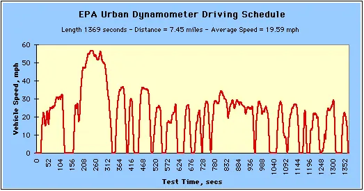
Steps for simulation of the generic battery model charge and discharge using the UDDS drive cycle is given below.
Step 1: Setup the UDDS input using the signal builder block.
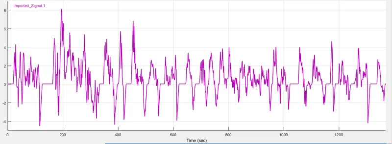
Use a signal builder block to create the drive cycle data of the UDDS cycle. The limitation of the signal builder is that it accepts data in the form of only the current profile. So, the speed v/s time data from the drive cycle should be converted to its corresponding current profile with respect to time. This data is stored in an excel file.
Import the data using the excel file to signal builder block
The current profile plot is given below.
Step 2: Configure the generic battery model
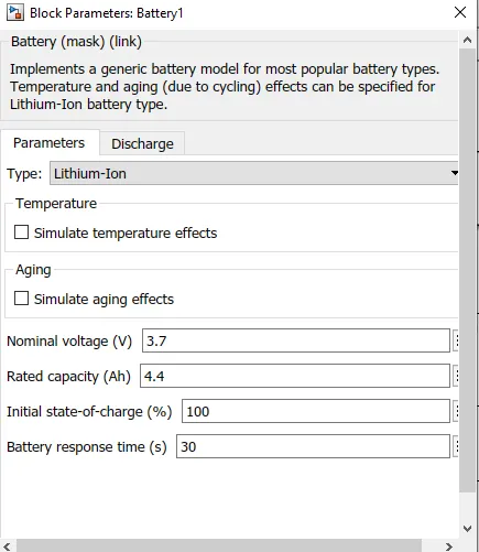
Here we choose a datasheet(attached file) of Li-ion rechargeable cell LIR18650-2600mAh to simulate the generic battery model.
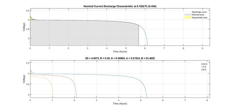
The Parameters are given below.
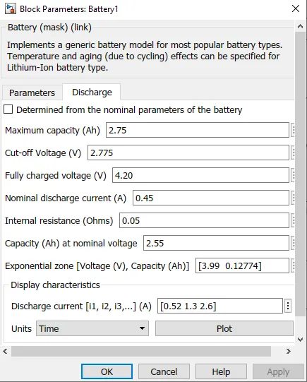
The discharge characteristics with respect to Time(hours) are given below.
The discharge characteristics with respect to Ampere-hour(Ah) are given below.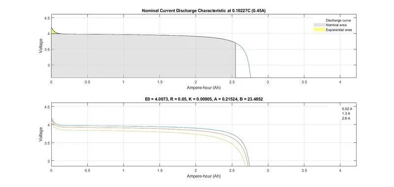
Step 3: Setup Controlled Current Source.
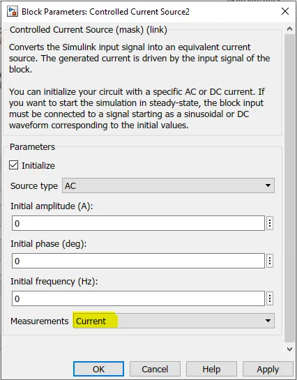
The controlled current source block converts the Simulink input signal into an equivalent current source. The generated current is driven by the input signal of the block.
Here we initialize the source type as AC and select Current in the Measurements drop-down button at the bottom
Step 4: Setting up the other blocks
The other blocks used are
Powergui :
The powergui block allows you to choose one of these methods to solve your circuit:
-
Continuous, which uses a variable-step solver from Simulink®
-
Discretization of the electrical system for a solution at fixed time steps
-
Continuous or discrete phasor solution
Demux/Bus Selector Block :
The Bus selector block extracts the components of an input vector signal and outputs separate signals. The output signal ports are ordered from top to bottom.
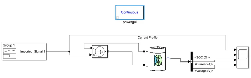
Scope: Used to display the output plots. Here we use 4 input ports for the scope to display the Current Profile, SoC, Current, and Voltage outputs.
The Simulink Circuit for generic battery model charge-discharge using UDDS data is given below.
OUTPUT
The output obtained is given below.
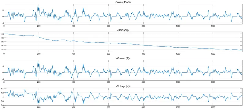 The state of charge(SoC) reduces to 92% from 100% after the entire drive cycle.
This shows the high efficiency of the system. The output current matches with the current profile input and this value varies between 6.8A and 4.5A.
The shape of the voltage curve is exactly opposite to the current curve.
The peak voltage observed is 4.3V and the lowest voltage is 3.7V. This ripple is expected in the case of Li-ion batteries.
CONCLUSION
Generic battery model charge-discharge is simulated using UDDS data.
The output is plotted and analyzed.
Simulation Matlab file and Datasheet attached.