Week 5 Battery characteristics using drive cycle
AIM - To simulate the generic battery model charge discharge using UDDS data.
INPUTS -
1.SIGNAL BUILDER -A driving cycle is a series of data points representing the vehicle vs. speed of time.The Signal Builder block allows us to create interchangeable groups of piecewise linear signal sources and use them in a model. We can quickly switch the signal groups into and out of a model to facilitate testing. In the Signal Builder window, create signals and define the output waveforms.The UDDS stands for Urban Dynamometer Driving Cycle.
In this model signal builder block is used to create the UDDS cycle and the only limitation of the signal builder block is that it accepts data only in the current profile form.

2.CONTROLLED CURRENT SOURCE - The Controlled Current Source block converts the Simulink input signal into an equivalent current source. The generated current is driven by the input signal of the block. The positive current direction is as shown by the arrow in the block icon.We can initialize the Controlled Current Source block with a specific AC or DC current. If we want to start the simulation in steady-state, the block input must be connected to a signal starting as a sinusoidal or DC waveform corresponding to the initial values.
3.GENERIC BATTERY MODEL - It implements a generic battery model for the most used popular battery types and also the aging and the temperature effects of the Lithium-Ion Battery can be specified.
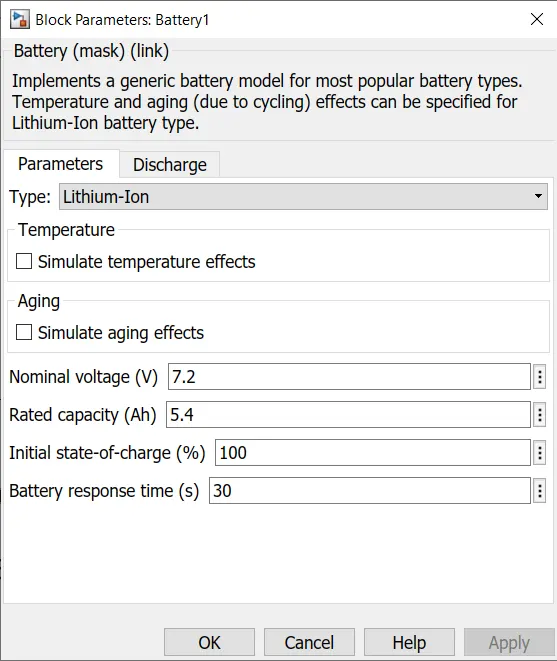
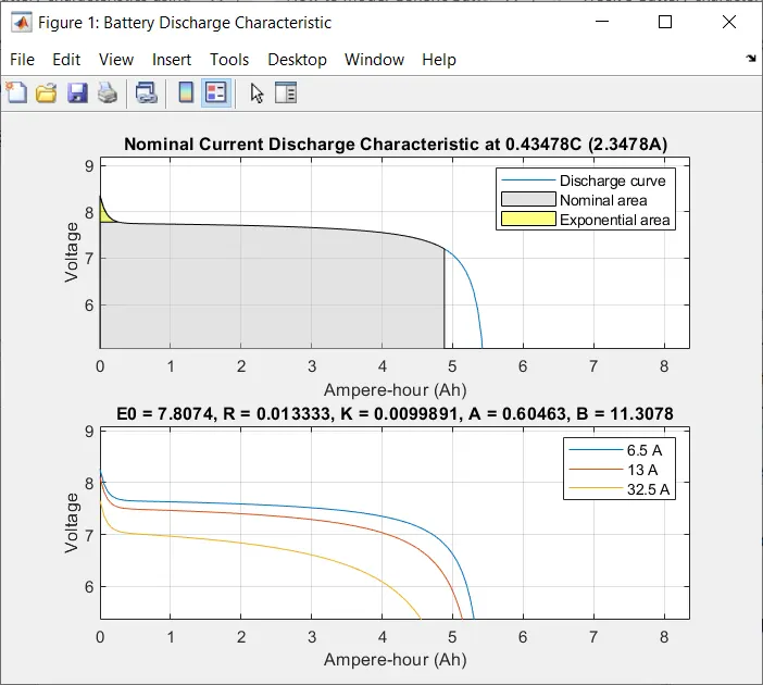
The nominal voltage of the battery is 7.2V and 5.4Ah capacity.
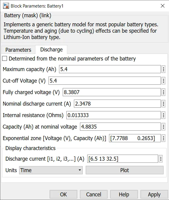
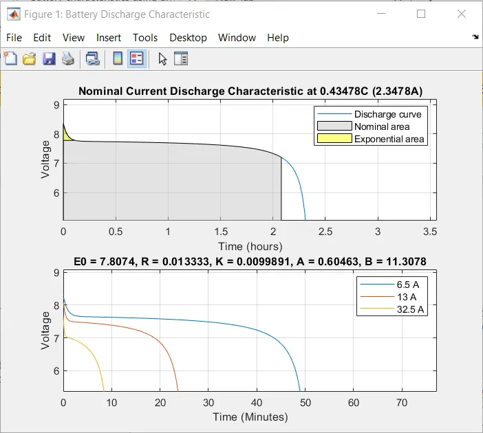
DISCHARGE CHARACTERISTICS -
Plot for voltage vs. time and voltage vs. Amp-Hr.
4.POWERGUI - The powergui block is used to simulate any simulink model containing simscape electrical power system blocks. It store the equivalent simulink circuit that represents state-space equation of the model.
5.BUS SELECTOR - The Bus Selector block outputs the signals you select from the input bus. The block can output the selected elements separately or in a new virtual bus.
SIMULINK MODEL -
STEPS-
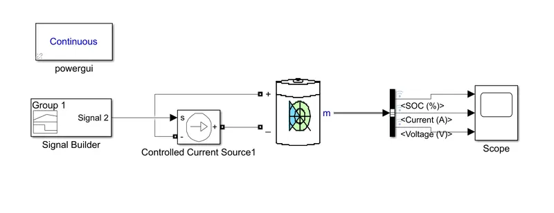
First open the signal builder block,then open the file menu in the file menu select the import file option and browse the UDDS file and select it.
The signal will be formed based on data from the UDDS file.THis signal is then given to the controlled current source.The +ve end of the controlled source is connected to the -ve end of the battery terminal and the -ve end is connected to the +ve terminal of the battery.
Then by double clicking on the battery block the input parameters are specified and is then given to the bus selector and from there to the scope.
RESULTS -
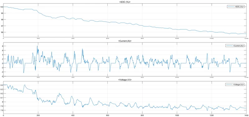
In the initial condition the SOC of the battery is 100% which means the battery is in the fully charged condition.In the SOC graph plot ,the SOC going up and down is due to the charging and the discharging of the battery.
In the current graph plot the negative drop indicates that the battery is discharging and the positive rise indicates the charging of the battery.
The voltage graph plot shows the drop in voltage as the battery goes discharging.