Week - 5 - 2D meshing for Plastic components
1. AIM: The Main AIM is to create a FEA model with all given quality parameters and with good mesh pattern for a given part .
2.Objective of the Project: The main objective of this project is to create FE model for given part and pre-processing it and make ready for solve.
3. Procedure:
-- Open the ansa software and a new dialogue box will open and we should insert "-performance_mode 3" in it and click onn OK.
--Click on file --> open , and select the model and double click on it which we want to open it.
The model will open.
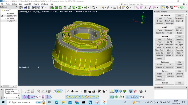
-- To capture the each abd every feature we should assign the element length as 1 by using lenght otption which is peresnt in the mesh moule by clicking on lenth option and select whole part and click on middle mouse button and pop up windor opens and assign the value as 1 and fir the same procedure fir macros option as well.
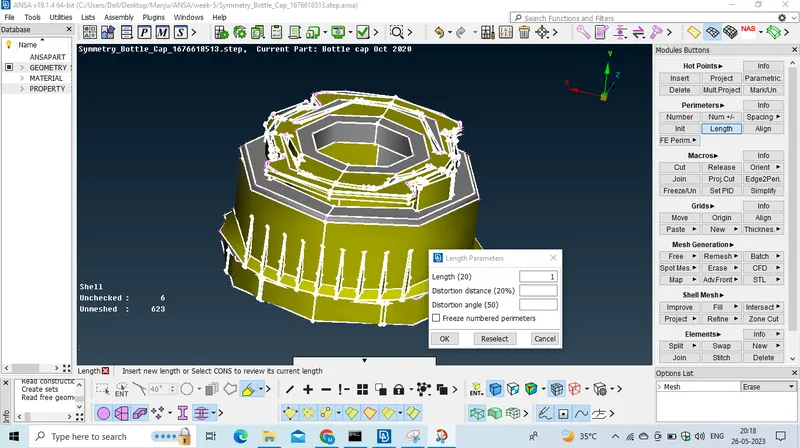
-- And Select Whole part and Give topo and click midle mouse button.
-- Now click on check managers option --> check manager--> check geometry and checkout the single con option and click on Execute option.
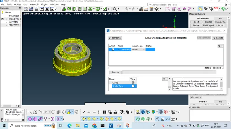
if geometrical errors occurs,
Select all the errors by clicking ctrl+A and right click on that and click on fix option it will fix errors automatically.
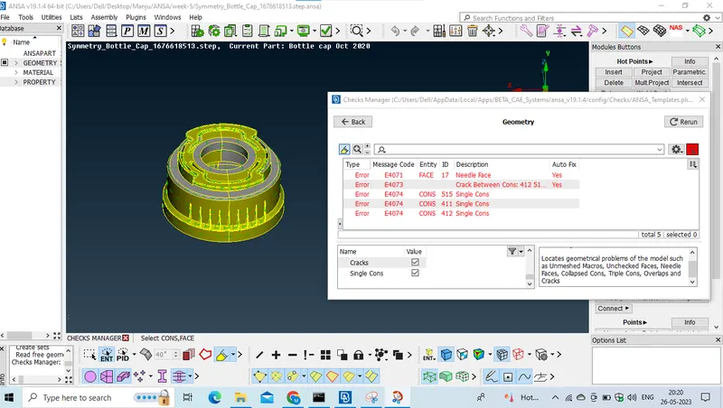
-- After clearing a geometrical errors we should create a mid surface of that.
We have to create midsurface
and now we should measure the thickness of the parrt from using the measure tool.
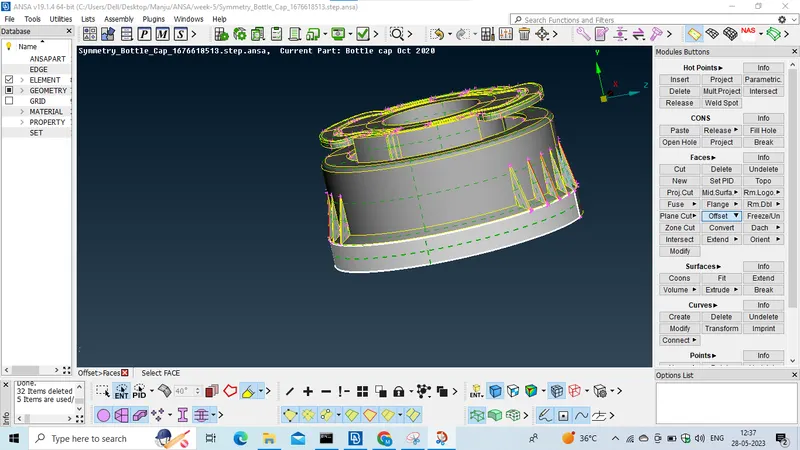
--Click on TOPO-->FACES-->OFFSET-->SELECT, and select one side of the surface, and click on middle mouse button and it will ask for direction we will assign the direction by giving negatuve sign and we should insert the offset value and click on ok and it will ask for wheather it should delete parent part yes or no so we should click on NO option and the midsurface will be generated and we should seperate it from parent geometry.
-- like this we have create midsurface for each part of the geometry with corresponding thickness.
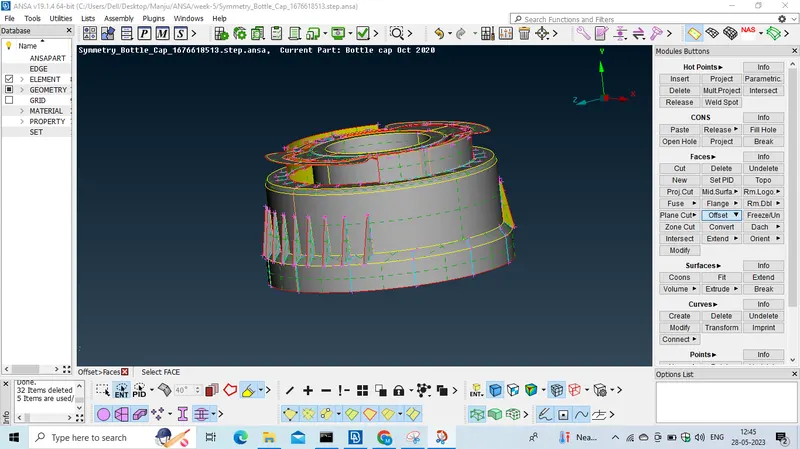
by selecting not option and select the PID region which is present in the right bottom. and select the parent geometry and click on middle mouse button and the parent geometry will hide and now create a PID for this midsurface,
by selecting SETPID option which is present under the topo module and select the entire midsurface and click on middle mouse button and the PID dialogue box wiil open and and click on the new option and a new dialogue box will popup and we should assign the the name for it and assign the thickness value in the thickness field, click on ok and now right click on that PID and click on apply and select entire midsurface and click middle mouse button, and mow the PID is set for the midsurace.
now set the mesh parameters by clicking mesh parameters option which is present in upper ribbon, and set the values,
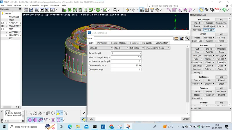
1. target element length-1
2. min value-0.5
3. max value-3 and click on ok.
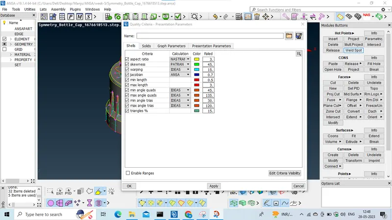
Now set the quality citeria values as given.
the values are
1. Target element length-1,
2. Min length-0.5
3. MAX lenngth-3
4. aspect ratio-3
5. warpage-15
6.skewness-45
7. jacobian-0.7
8. min quad angle-45
9. max quad angle-135
10. min tria angle-30
11. max tria angle-120
12. tria %-15.
and now click on presntation parameters and check on the tria & and select all details and click on ok.
now delete unnecesary hot points by using delete option which is present in mesh module
and delte unnecessary cuts by using cut option.
and now messure the distance between the nodes by analysing the elemental failure if in case the the distance is less than the minimum value then we can defeature it.
and now we should generate mesh on it.
Generating mesh on the midsurface.
Now the active the hidden option which is present in the bottom.
to create mesh select the best option MESH-->MESH GENERATION-->BEST
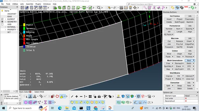
and select the macros area and click on middle mouse button and the mesh will generate and see if any element is failing for any qauality paramaters so if fails then we should reconstruct the mesh by using reconstruct option present in the shell mesh module and selcet the area and click middle mouse button
and in some case use paste and move options which are present in the grids module.
and to avoid the trias select the split option and split or swap the trai in order to avoid them
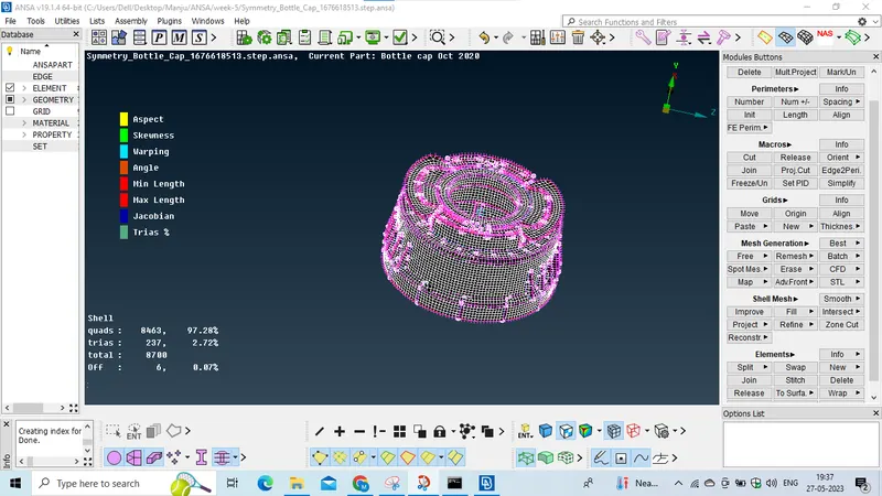
and finally the mesh has genrated on the misdurface.