Week 3 - 2D meshing for Sheet metal
AIM : The main AIM is to perform preprocessing on given cad model with achieving quality mesh.
Objecctives of project : The main objective of this project is to create FEA model for front hood inner panel and performing preprocessing on it and make it ready for further process.
Procedure:
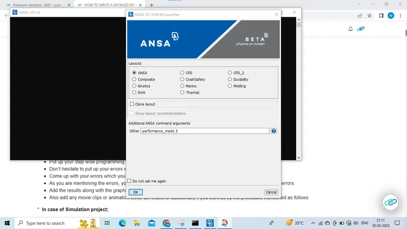
- Open the ANSA software,
a new window will open and in the text field we have to enter "-performance_mode 3",
and click on "OK" the software will open.
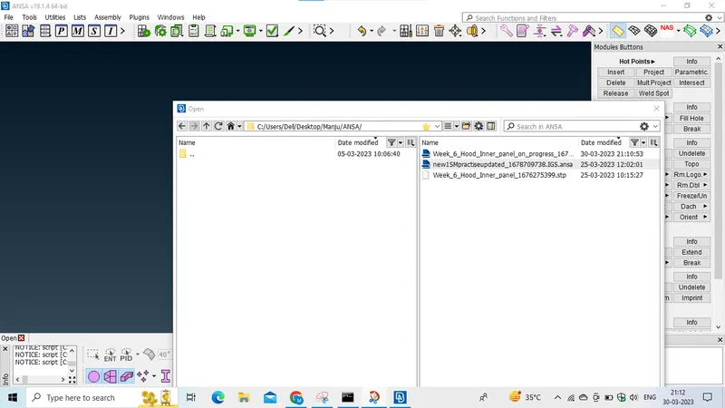
- Now open the cad model by clicking File ---> Open --> select --> and click on open button at bottom, now the model will opens.
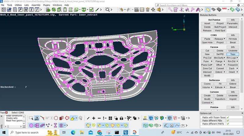
- At first we have to clear all the geometrical errors, by using topo option Topo --> Faces-->Topo select all the cons and click middle mouse button.
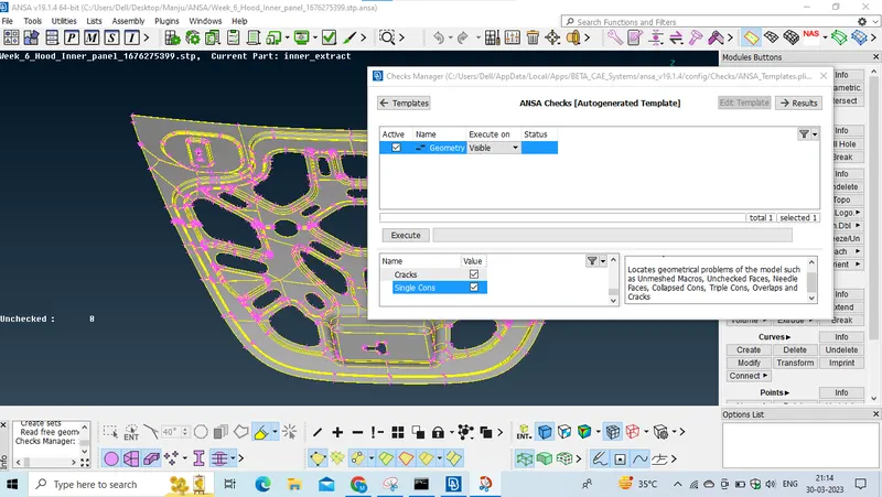
- now we have to perform check geometry operation, at top ribbon Checks manager-->check geometry--> checkout for single con checkbox and click on execute.
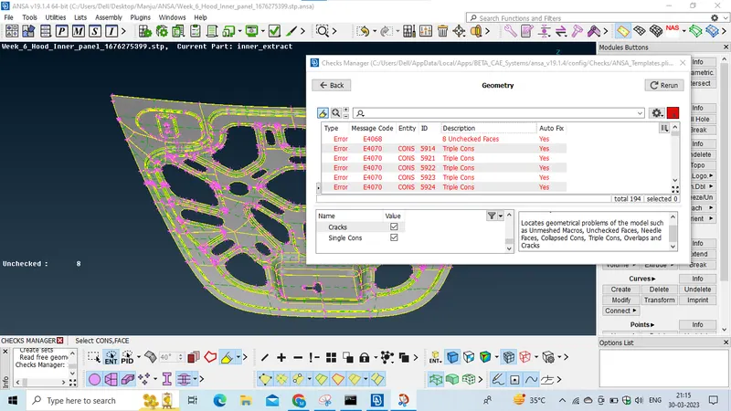
all the geometrical errors will show and select all the errors and right click on them and click on fix option.
so some of the errors will fixed automatically.
and some remaining errors we have to clear it manually. so observe where the error is occuring and we have to clear it.
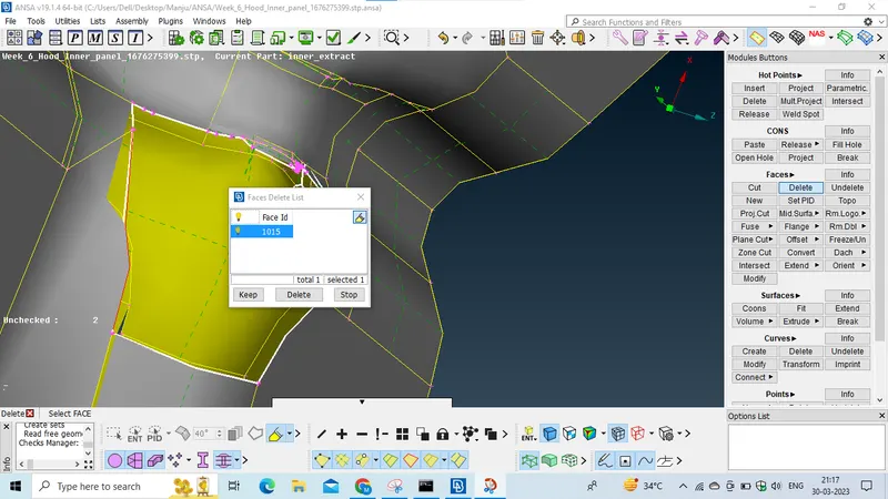
- zoom on to unchecked faces and delete the unchecked faces. by using delete option Topo-->faces-->delete.
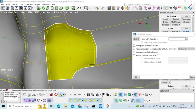
- and create new faces by using fill hole option Topo-->cons-->fillhole. and select the cons and clcik middle mouse button the new surface will created. like this we have to clear all the geometrical errors.
- and after clearing all the geometrical errors now once again check the geometrical errors.
if status is ok then we can proceed for further steps.
-and now we have to extract the mid surface from parent model.
-Now we should measure the thickness of the model by using measure tool present over top side and by selecting the measure tool click on one side node and other side node and click middle mouse button, and check some other areas as well, so the thickness is the 0.75mm
-create the surface either positive side or negative side for it by using orient option which is present in Topo--> faces-->orient and left click on the surface it will change its colour.
now extract the mid surface by using offset tool, Topo-->faces-->offset-->select, and select the feature area option whicj is present in bottom ribbon, and select the whole surface and click middle mouse button, the new popup window opens we have to assign the value for offset if we are selected negative side then we have to give negative value as -0.75/2 and click on OK now the misdurface is generated.
Seperating the midsurface from parent model.
- select !not option and select Macros option and click on the surface and click middle mouse button the surface will hide and select the neighbor option which is present at bottom and now only the parent model wiil visible on the screen now and click on the invert option the midsurface will visible on the screen now and now lock the screen.
-set Pid for midsurface.
-by selecting entire midsurface and clickon set Pid option Topo-->Faces-->set pid, the new window will open now and click on new option which is present at the bottom and popup window will open and assign a unique name for it and click on ok,
and right click on that midsurface Pid select apply and select the entire midsurface and click midde mouse button. now Pid is created for the midsurface.
lock the screen.
Now setthe elemental lenght by using length option, Mesh-->perimeter-->length & select the entire object and click the middle mouse button a new window will open and give the length value as 5 and apply same for the macros as well.
- set the mesh parameters by using mesh parameters option present at the topside, click on mesh parameter a new window will open and give the values as mentioned,
Target elemental length-->5
minimum length-->2
Maximum length-->7, and click on OK.
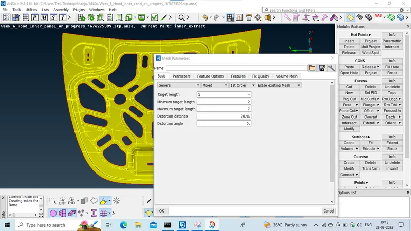
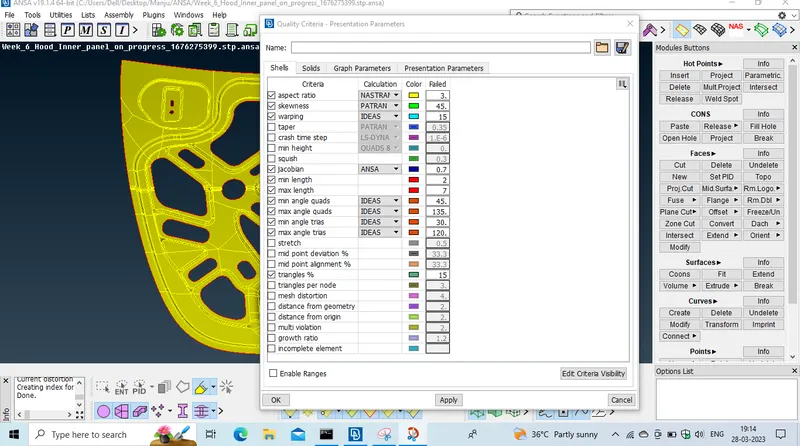
- Set the quality criteria as given, click on wuality criteria option a new wuality criteria window will open and assign each value as mentioned,
Target/Avg length-->5
Min Length-->2
Max Length-->7
Aspect-->3
Warpage-->15
Skewness-->45
jacobian-->0.7
Min quad angle-->45
max quad angle--> 135
Min tria angle--> 30
Max tria angle--> 120
Tria percentage--> 15,
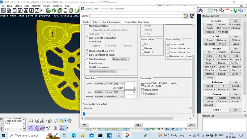
and now click on presentation parameters and check on the element %, and drag the button for all details,
and click on OK.
- now delete the unwanted hot points by using delete option, Mesh-->hot points--> delete, by selecting the hot points which needs to be deleted.
-Delete unwanted construction lines, by using cut option, Mesh-->Macos-->cut, by right clicking on the construction lines which needs to be deleted.
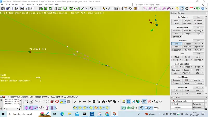
- now measure the elemental size by using measure tool where asume that the element can fail for quality ther we should measure the element size if it is less than the required value and we should make defeaturing on it, bby making alteration on the construction lines.
- Genereating mesh.
- active the hidden option at bottom while creating mesh.
- we have to create mesh by using best option, Mesh--> mesh generation-->best,
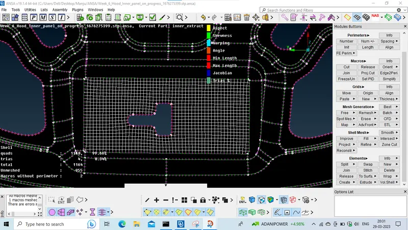
and select the macros area and click on middle mouse button teh mesh will generated and now check if any element id failing for quality by observing the colours and do modification on it by using reconstruction option,
Mesh-->shell mesh-->reconstruction,
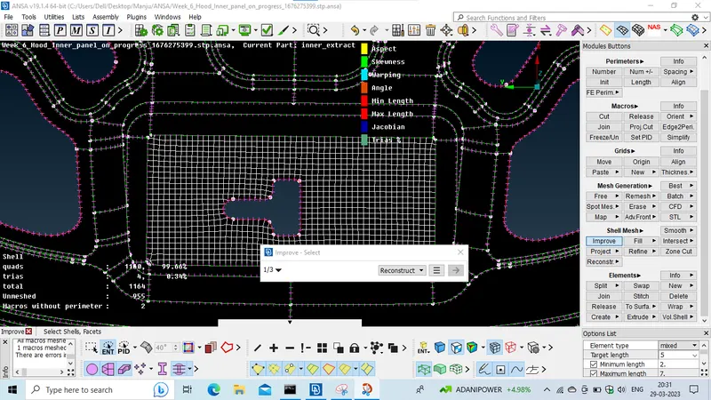
and select the elements and click middle mouse button the software will give a better mesh flow.
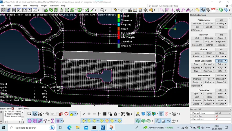
to avoid the trias use the split option, mesh--->elements-->split,
and by clicking on vertices of tria we can split i.
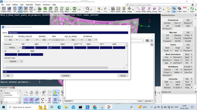
after creating a mesh, we should assign the thickness value for the midsurface by clicking on Pid option and click on the midsurface option and assign the thickness value for it and click on OK.