Week - 5 - 2D meshing for Plastic components
CHALLENGE 7: 2D MESHING OF PLASTIC COMPONENTS
OBJECTIVE:
To conduct geometry cleanup and mesh the mid-surface for the Plastic Bottle Cap CAD model as per the given quality criteria.
CAD MODEL:
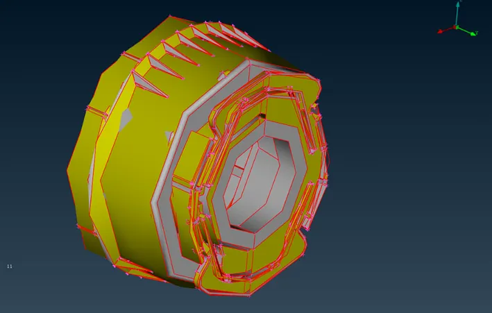
Model of Plastic Bottle Cap
PROCEDURE:
- Importing CAD model:
- Open the geometry model. Use Topology option to clear the cons and check the model orientation using Entity Drawing Style in Menubar.
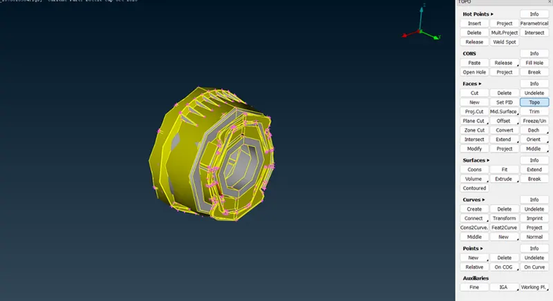
- Check and assign PID and Materials from Lists menu (if required).
- Geometrical Clean-up:
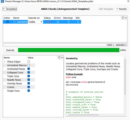
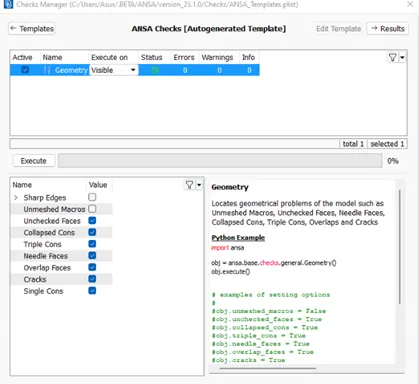
- Check for geometrical errors using Checks Manager option. Execute the geometry after selecting the required options.
- Clear the errors using auto-fix option in Checks Manager from Tools menu.
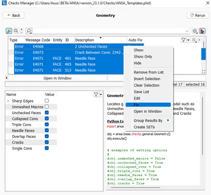
- If the errors still persist, then they have to be corrected manually using TOPO options.
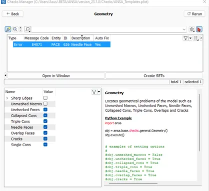
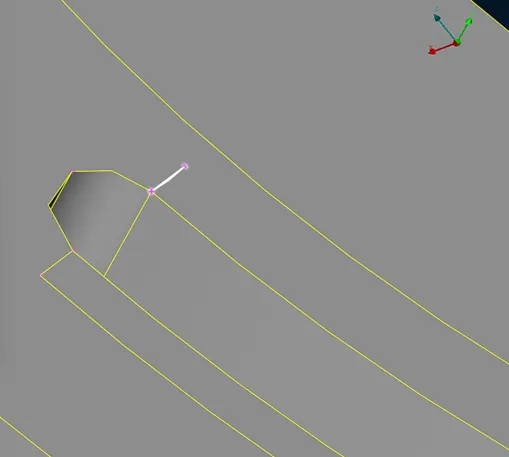
- Here the highlighted regions in the model indicates faces or cons that needs to be corrected.
- Rerun the geometry check again for zero errors.
- Creating Mid-surface:
- Check the model thickness at different spots using Measure option in Utilities menu.
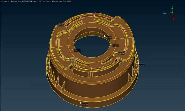
- Store the measurement data in Database if required.
- The given model has varying thickness throughout as per the measurement data shown above.
Extraction of mid-surface of the model can be done using Mid-Surface option/manual method from Topo menu. Initially we follow the auto-mid extraction using Mid-Surface (Casting) option.
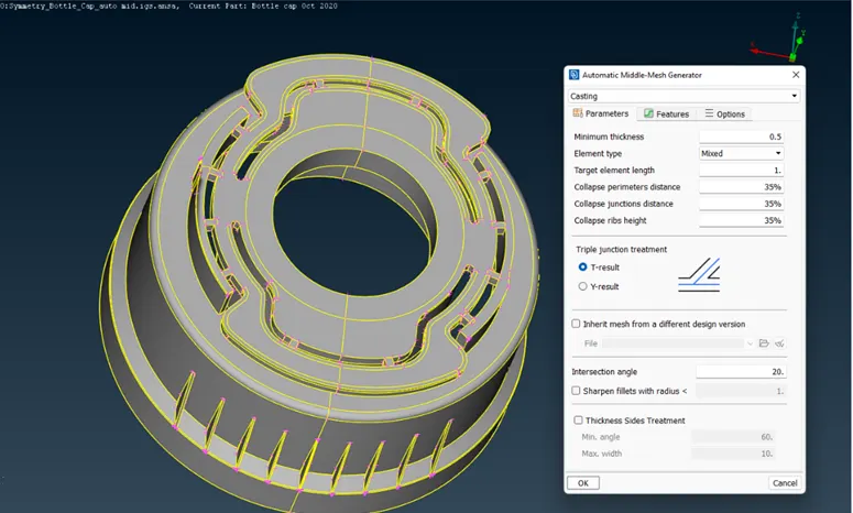
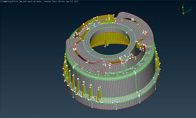
This method obtains broken/deformed mid-surface for certain features as shown below.
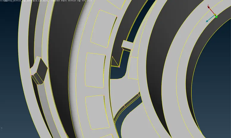
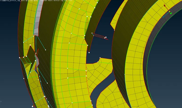
We shall try to obtain proper mid-surface for all the features using manual method.
- Offset option can be used to create mid-surface for features of uniform thickness.
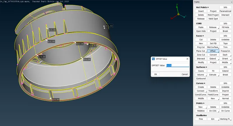
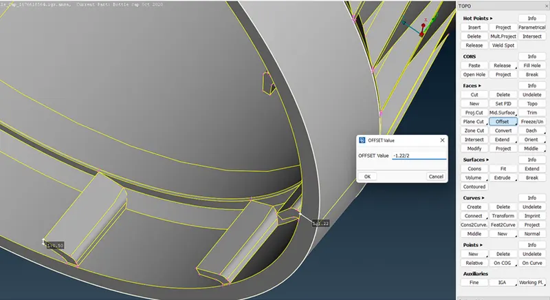
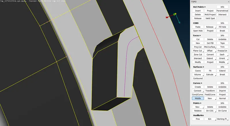
- Middle option from Curves helps to form outlines of mid-surface for features/area with varying thickness.
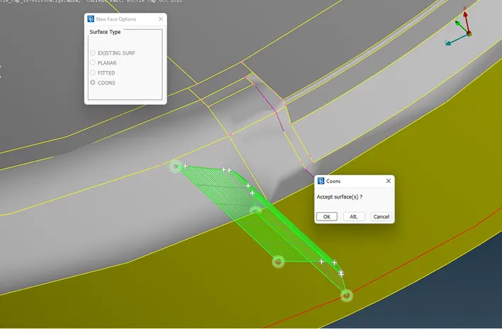
- New Face option can be used to create the surface using the outlined curves.
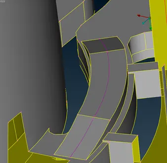
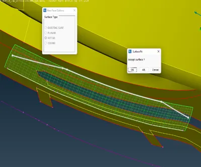
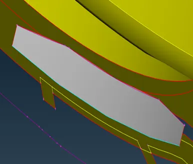
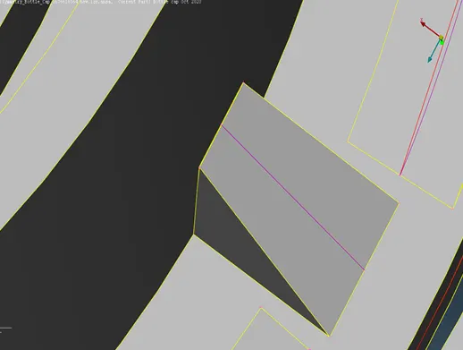
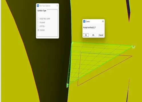
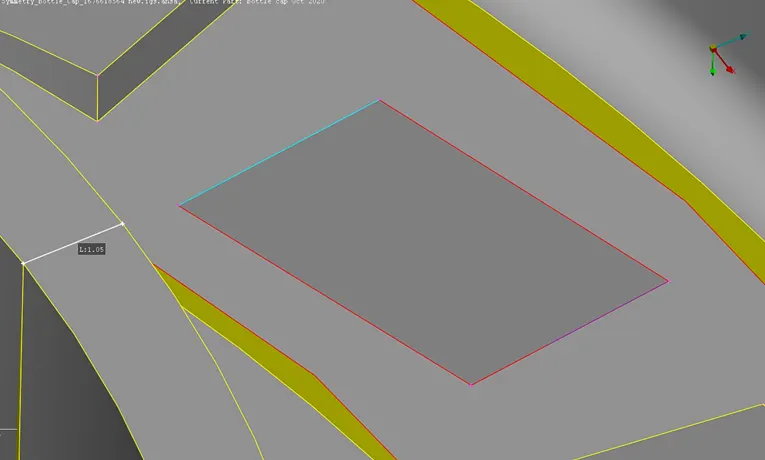
- The feature shown below also can be formed using Curves and Cons projection.
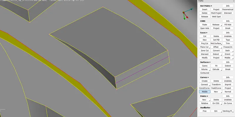
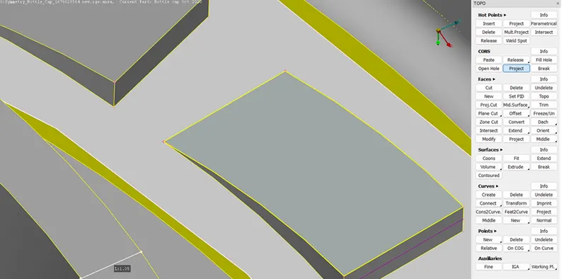
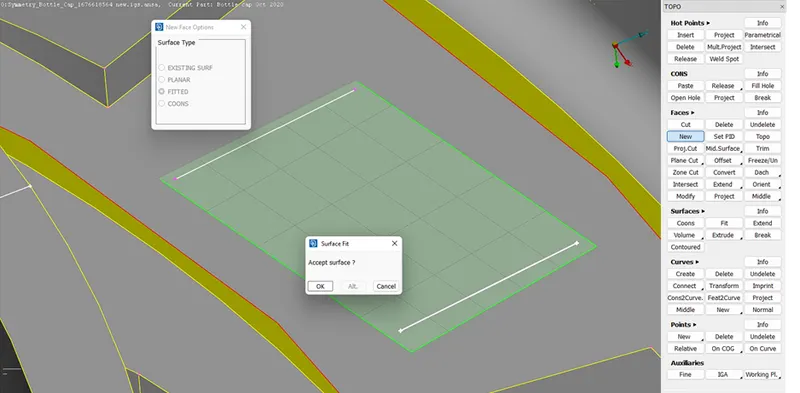
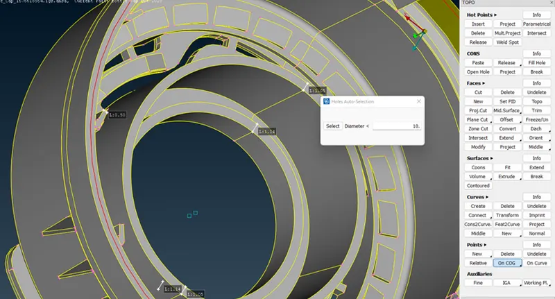
- Inorder to replicate certain features around a surface, we have to create few reference points as shown below.
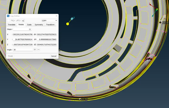
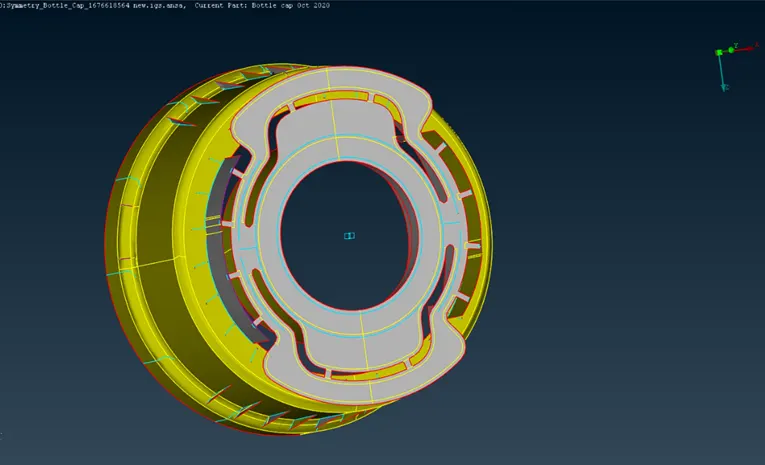
- Assign a new PID and thickness value for the created mid-surface.
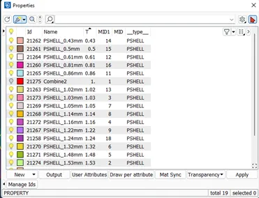
- Store Lock the mid-surfaces and parent assembly model view separately.
- Quality Criteria and Meshing:
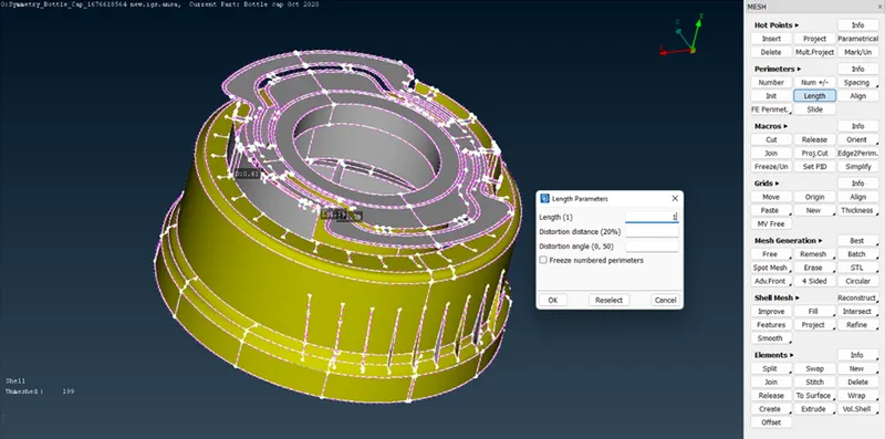
- Change the Length Parameter to value 1 for both Perimeter and Macros.
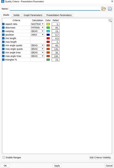
- Select and enter the values required in the Quality Criteria box from Utilities menu.
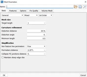
- Input the required mesh length and minimum length in Mesh Parameters from Utilities menu.
- Select Classical Mesh option from Mesh module.
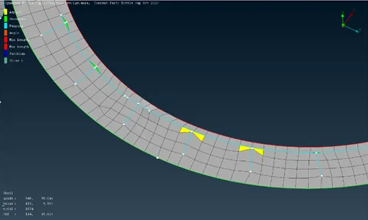
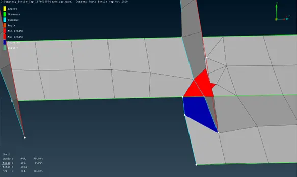
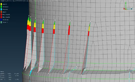
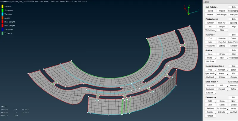
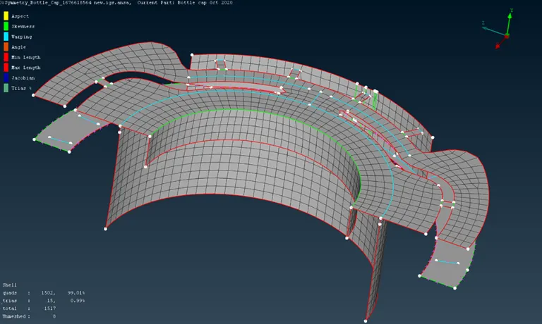
- Mesh the features sequentially and use Shadow Drawing Style to view the mesh quality deviations.
- Correct the mesh flow and quality using Mesh options.
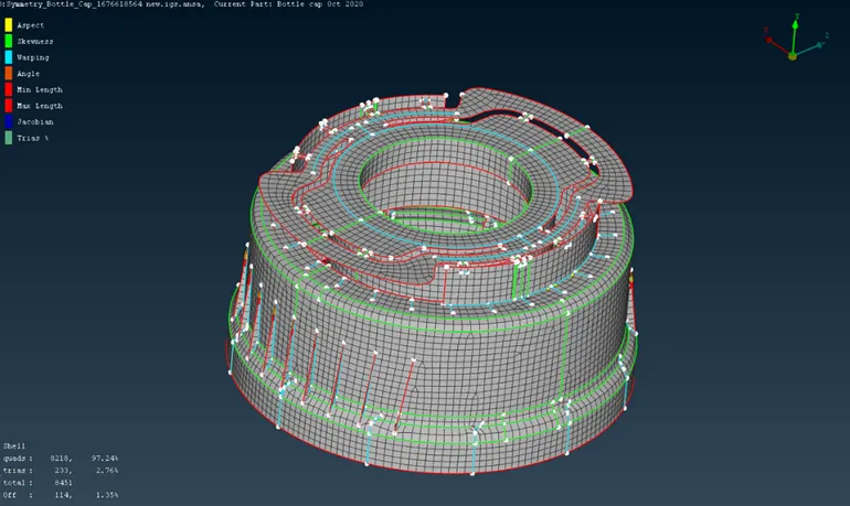
- Final Model:
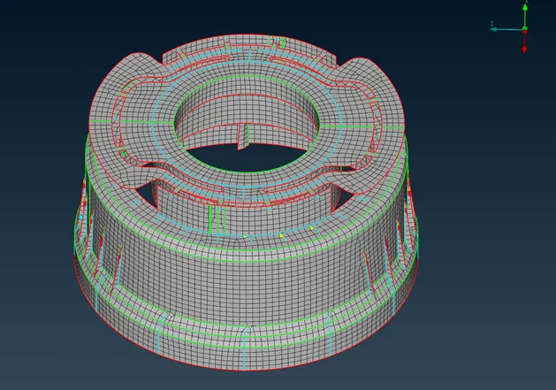
RESULTS:
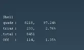
The given Plastic Bottle Cap model has been completely meshed by assigning thickness but certain elements has failed quality criteria due to constraints induced by triple cons.