Meshing of IP Substrate
Report on IP Substrate
Aim: For the given component, check for the geometrical errors and mesh with the given element Quality criteria. After meshing the component the thickness has to be assigned.
Mesh quality criteria are as follows: -
|
S.No |
Quality Criteria |
Value |
|
1 |
Target/Average length |
4 |
|
2 |
Minimum Length |
2 |
|
3 |
Maximum Length |
6 |
|
4 |
Aspect |
3 |
|
5 |
Warpage |
15 |
|
6 |
Skewness |
45 |
|
7 |
Jacobian |
0.7 |
|
8 |
Minimum Quad Angle |
45 |
|
9 |
Maximum Quad Angle |
135 |
|
10 |
Minimum Tria Angle |
30 |
|
11 |
Maximum Tria Angle |
120 |
|
10 |
Tria Percentage |
15 |
Procedure:
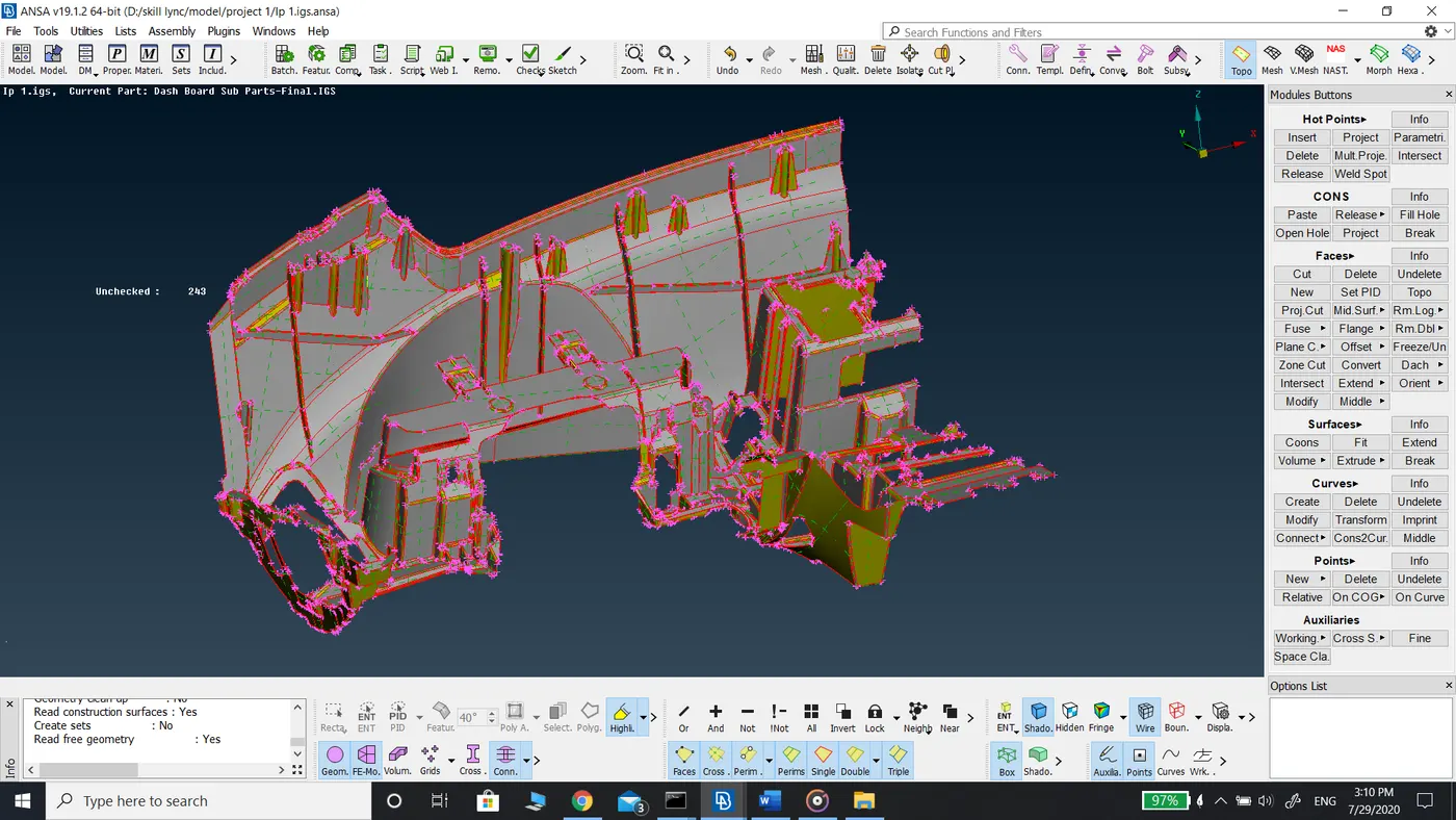
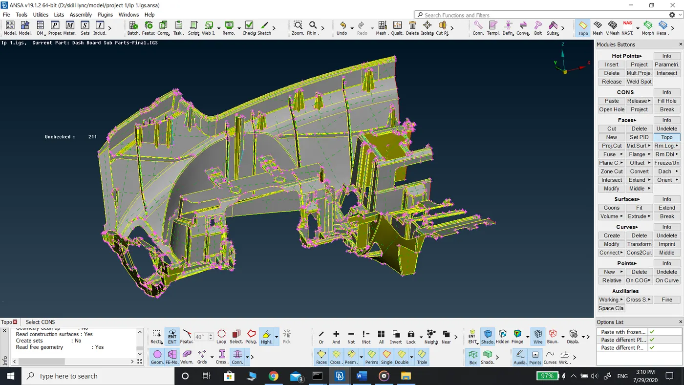
- After downloading the model, topo command is applied to the entire model to connect all the features to make it as a single connected model.
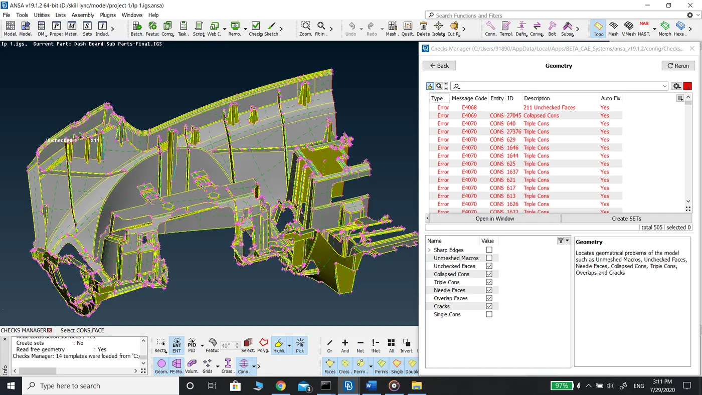
- A geometry check is performed to model to check for cracked faces, unchecked faces, triple cons, and single cons. The errors generated are fixed either manually or by applying an auto fix.
- Once all the geometry errors are cleared the model is reviewed area by area to check for overlapping faces near corners of the fillets or where two or more fillets join. Those faces are deleted and created new faces using the faces-new command. This is done for the proper extraction of the mid surface.
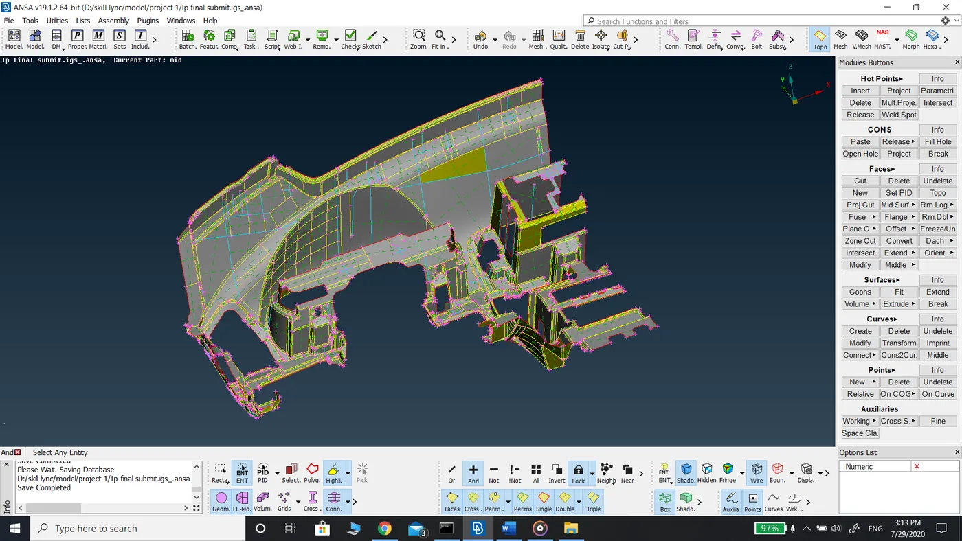
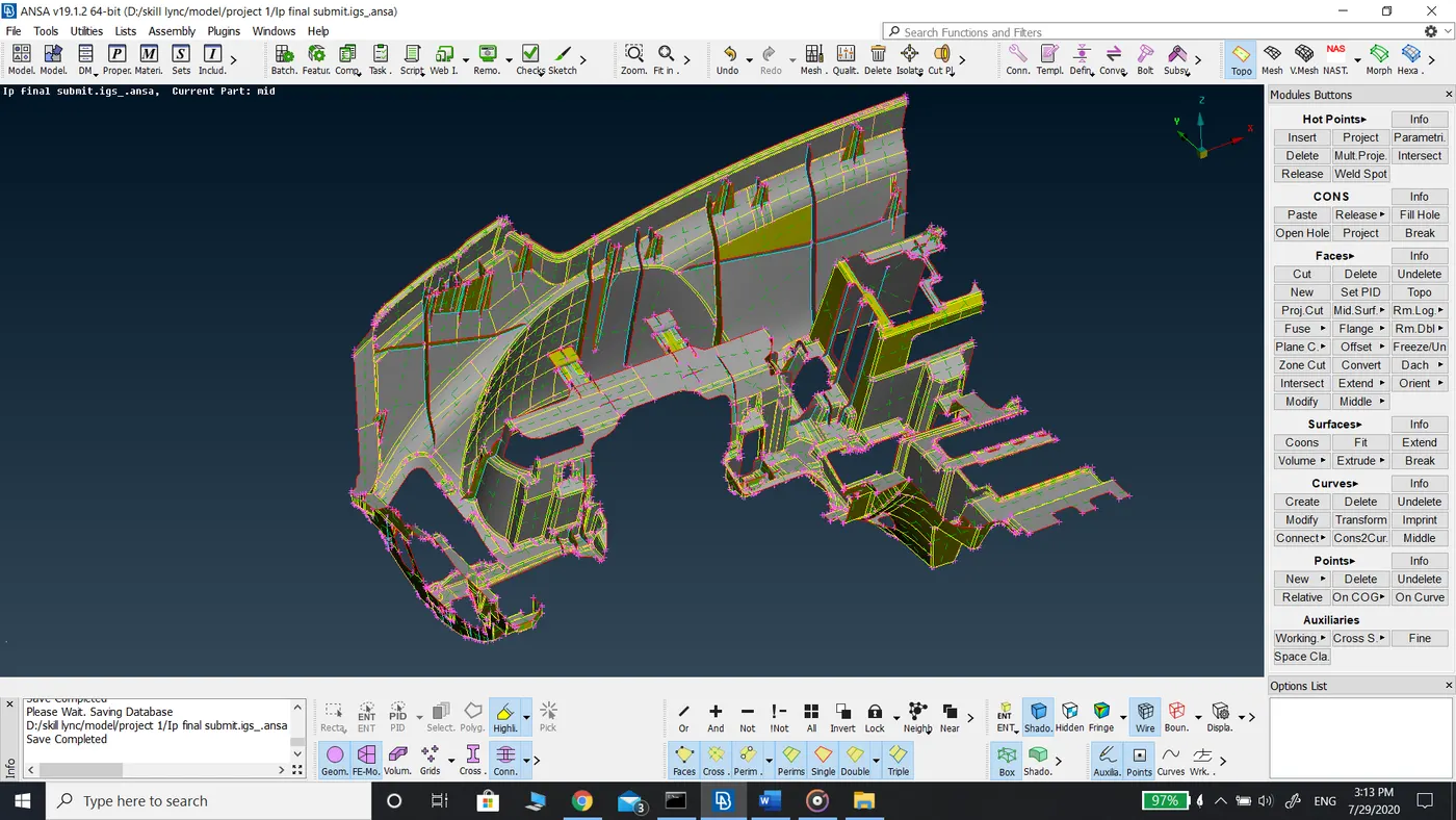
- Once the parent model is prepared for extraction of the mid surface, the mid surface is extracted using a combination of commands such as offset, middle under faces tab in topo mode.
- The main surface is extracted using faces offset with feature angle selection with an offset of 0.3 mm as the thickness of the main surface is 0.6 mm. The reason for the selection of this method is that the IP Substrate model contains ribs and flanges and it is divided into main faces with several fillets. Hence offset with feature angle selection allowed me to select all the faces whose angle is less than 40-degree angle and offset to the center of parent geometry.
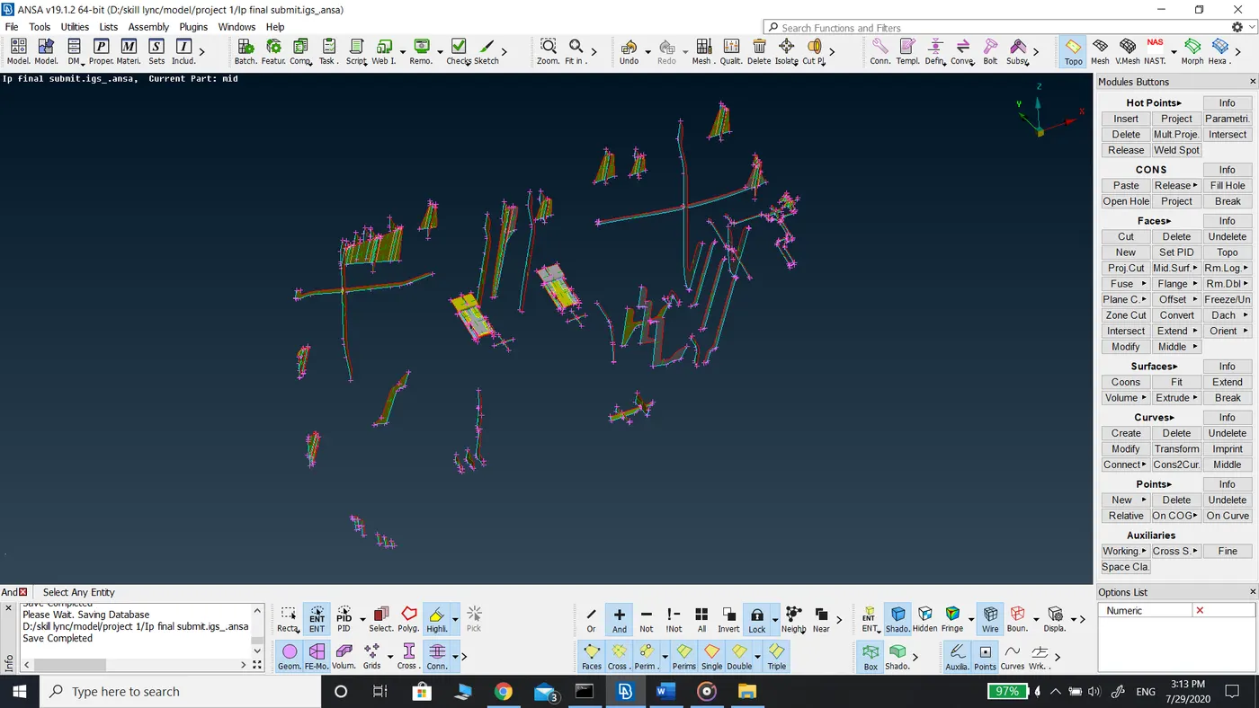
- The mid surface is for the ribs and flanges are extracted using faces middle command as the faces of the ribs are exactly opposite to each other.
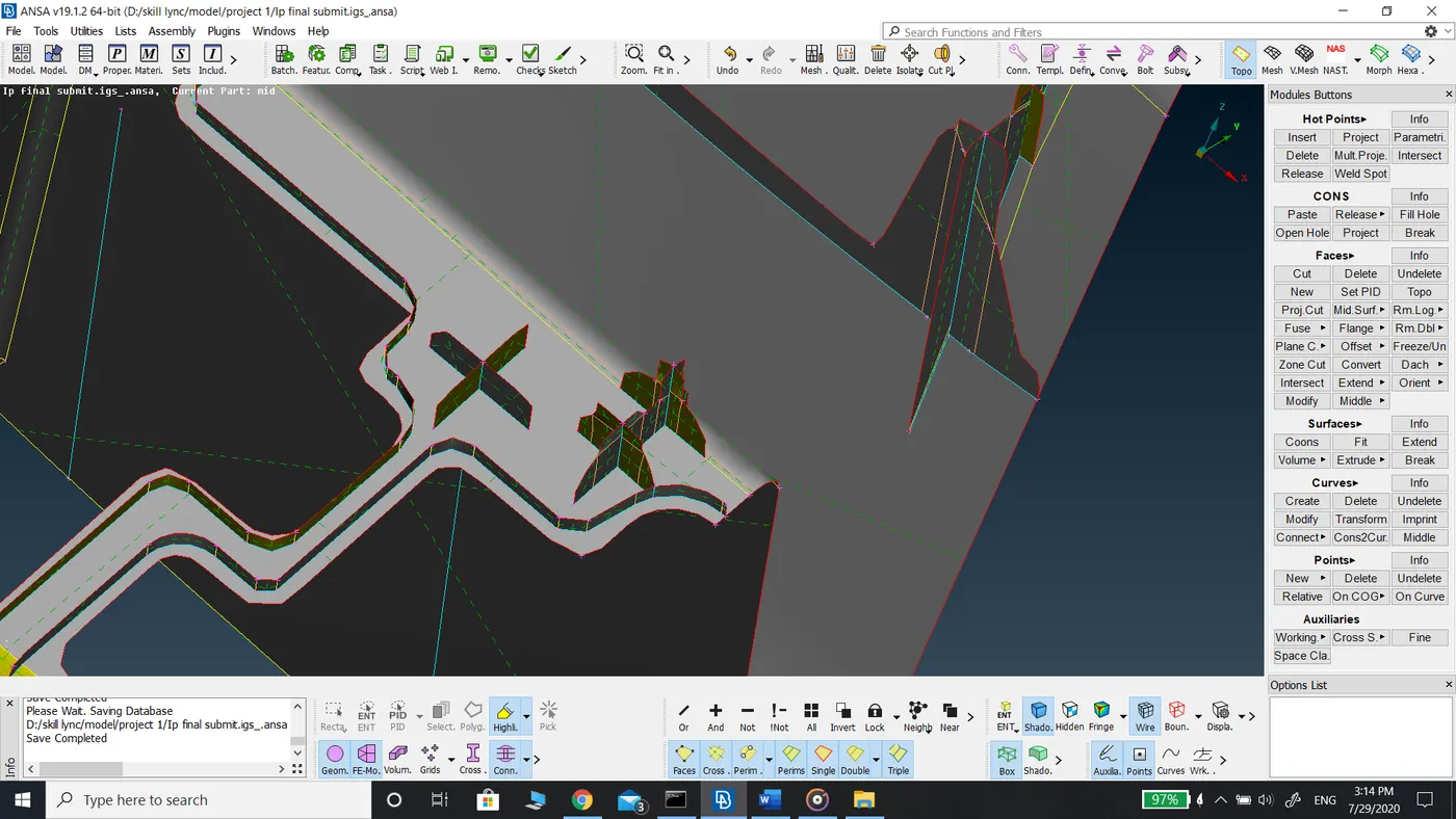
- The circular features in the model are represented by the Cross symbol as shown in the figures below. They are created using faces cuts, cutting in the middle of the circular feature, and using cons to curve in curves tab and generate new faces using the curves generated.
- Once the extraction of the mid surfaces for all the faces is complete, a geometry check is performed to ensure there are no cracks and unchecked faces in the mid surfaces. Before clicking on run in geometry check uncheck triple cons and single cons and mid surface contains single cons and triple cons are generated when you extend the mid surface of ribs and flanges to the main surfaces.
- After the extraction of the mid surfaces target length of 4mm is assigned to the model using length command in perimeters in mesh mode.
- The model is reviewed area by area to check the perimeters are matching the requirements.
- Defeaturing is done to those areas who have a length less than the target length. It is done using the cut command in macros in topo mode. Unwanted cons, Hotpoint, curved cons, and cons on straight surfaces are hidden for good mesh flow.
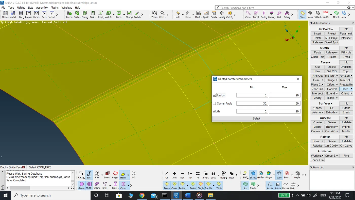
- Fillets having less than the required minimum length that is 2mm will fail for minimum length mesh quality criteria. To eliminate this error Dach command divide face under faces tab is used. This command creates a cut in the middle of the fillet which represents the fillet and hiding the other lines which were representing the fillet.
- After defeaturing the component, a geometry check is performed once again for geometrical errors.
- The model is opened in mesh mode and mesh quality criteria are entered in the quality criteria and mesh parameters are also entered.
- Meshing is done using the Best mesh with a mixed element type for good mesh flow.
- Mesh is generated for the main surface first to generate good mesh flow and also to ensure the all the fillets and features are captured properly.
- Once the mesh is generated, it is reconstructed using reconstruction command in shell mesh to eliminate any mesh quality errors.
- The component is reviewed area by area for proper mesh flow and to check for rotating quads and opposite triangular elements.
- Rotating quads and opposite triangular elements are solved using a combination of commands such as split, paste, join, swap, and smooth.
- While solving rotating quads and tria elements the component is checked for off elements using hidden drawing style.
- Those off elements are also solved using a combination of commands mentioned above.
- Once the mesh is generated for the main surface then meshing is done for the ribs and flanges. The reason for not generating a mesh for all the surface at once is the presence of triple cons in the mid surface which would generate unwanted tria elements while eliminating opposite tria elements in the main surface.
- After the completion of mesh generation, Property ID is assigned to those features of different thicknesses using Set PID command under faces tab in topo mode.
- After assigning PID, the shell elements are drawn as solid elements under the presentation perimeters tab in the quality criteria tab.
Learning Outcomes: -
- Dach command- This function replaces a single fillet or a serious of fillets with the corresponding tangent Faces creating a sharp corner.
- Capturing of Solid components with 2D mesh elements.
Conclusion:
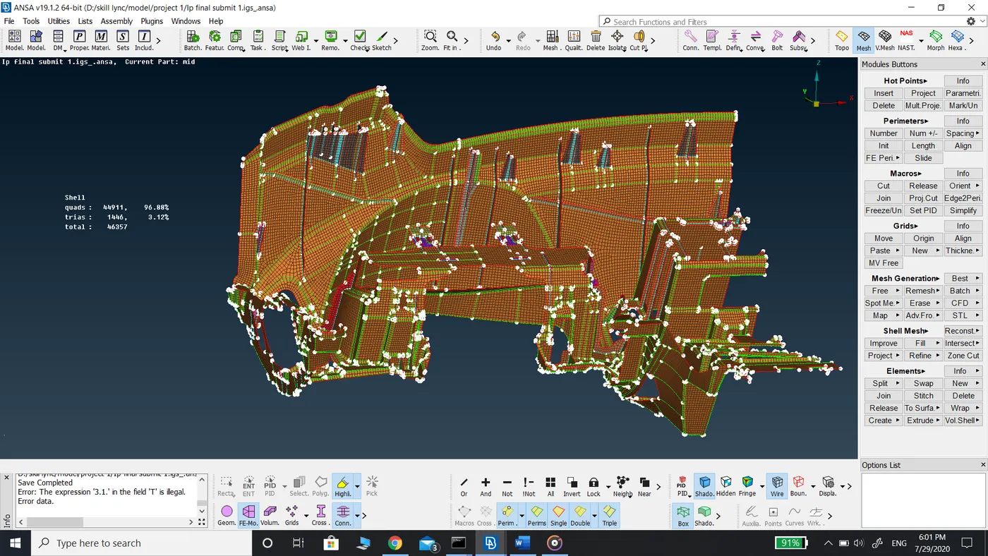
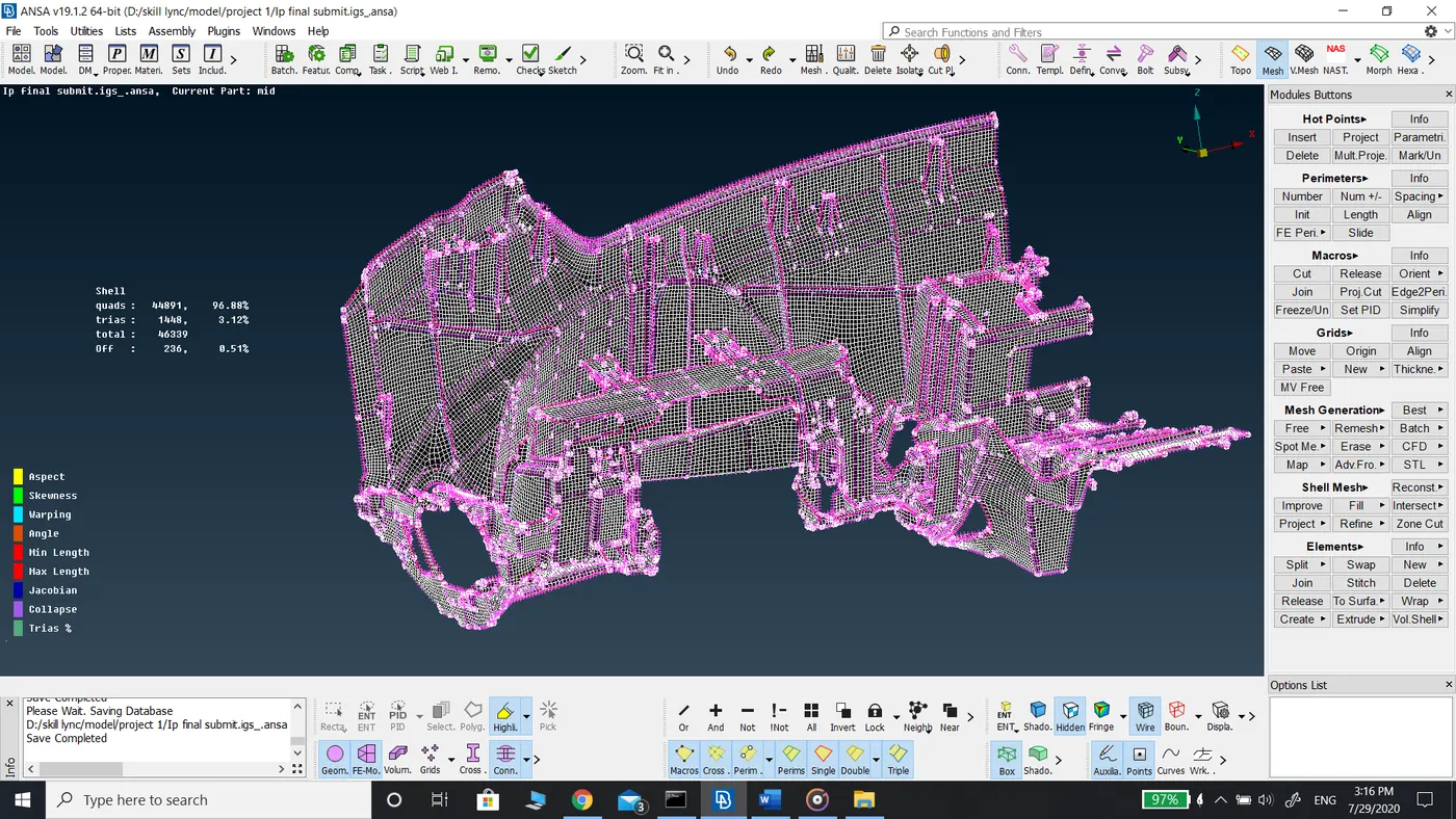
The given model IP substrate to which mid surface is extracted and meshed with the given mesh quality criteria mentioned above. For which given below details of elements generated.
|
Total elements |
46357 |
|
Tria Elements |
1446 (3.12%) |
|
Off elements |
236 (0.51%) |
|
Quad Elements |
44911 (96.88%) |
Before Topo
After topo
Geometry Check errors
After solving geometry check errors
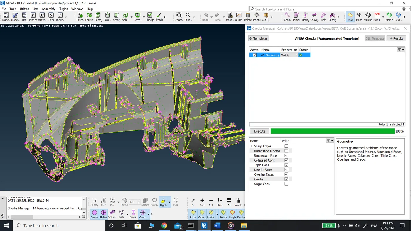
The mid surface of the main surface
The mid surface of the ribs
The mid surface of the entire component
Representation of Solid features in 2D mesh
Solid feature in the Parent model
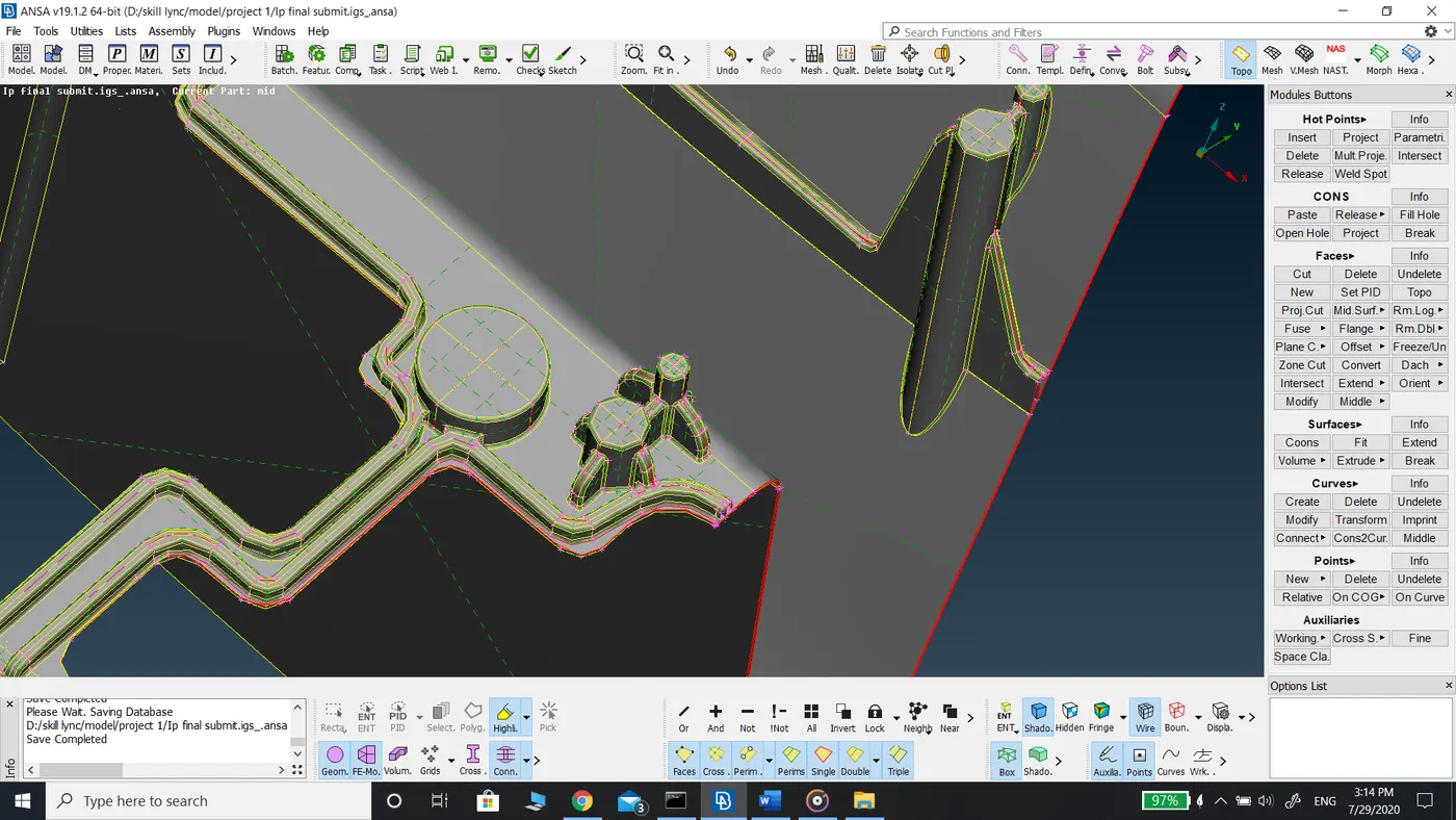
Represented in 2D mesh
Applying Dach divide face command to those fillets failing for minimum length criteria.
Mesh of the model in shadow view
Model after assigning PID thickness