Week 5.2 - Multi Level Meshing
AIM : To create the Multi-level Meshing to resolve the given CAD objects in Ansys Icepak.
OBJECTIVES :
- Create non-conformal mesh assembly for the required components to optimize no. of cells.
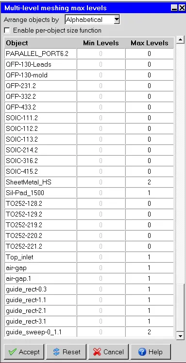
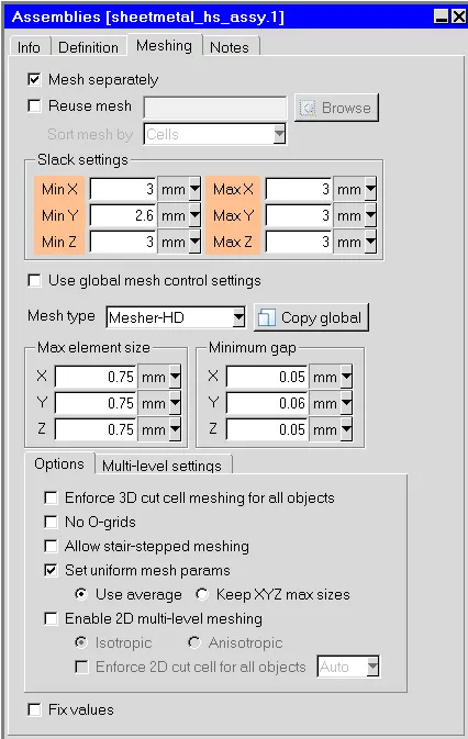
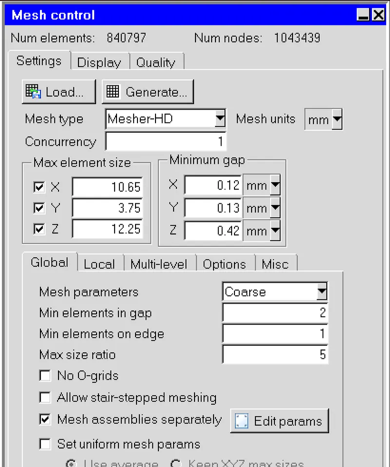
- Use set uniform parameters and use average on 1 assembly, in multi-level meshing tab allow multi-level meshing up to level 2 for the objects.
- Generate mesh & observe in mesh reduction.
- Do visual inspection & check for quality.
INTRODUCTION :
Multi-Level meshing is the tool available in Ansys Icepak which is used to mesh and capture complex CAD geometry. Multi-level meshing tool allows to set levels to different components and zones in the geometry setup. For the regions where CAD is very important or CAD is very complex there the mesh will be very dense and where there is less complex geometry or less important area there will be coarse mesh.
The level of multi level mesh goes as follows -
- 0th Level - the mesh cell is the gneral coarse initial mesh cell size.
- 1st Level - will be 4 cells equal-divides of the previous cell.
- 2nd level - will be again each 1st level cell is divided into 4 parts.
like that at every level the each previous cell is divided into 4 equal parts.
STEPS / PROCEDURE :
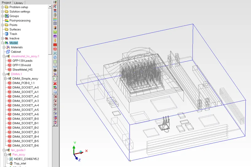
1) Loading Geometry/the given case setup from the project file.
Following are the Geometry of the given Case -
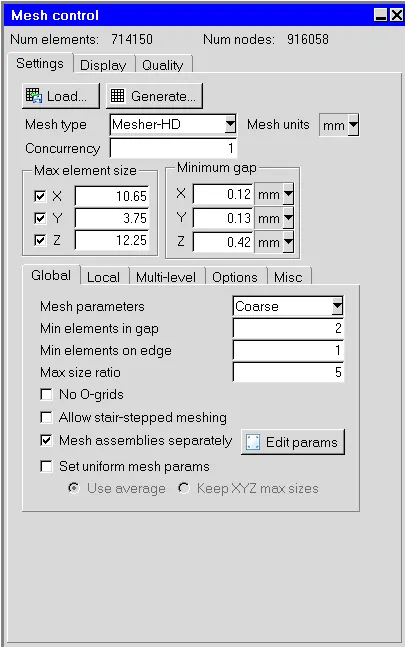
2) Generating Preliminary coarse mesh on the gemotry as it is.
Following the mesh size of the generated mesh -
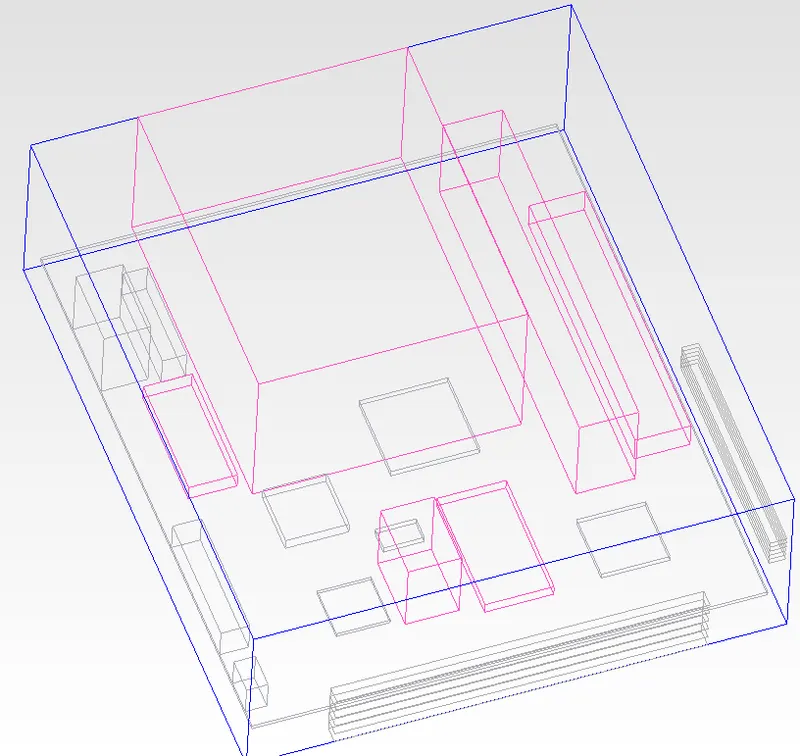
3) Creating Mesh assembly and non-conformal meshing for optimizing the mesh count for the simulation case.
Following is the mesh assemblies created and non-conformal meshing mesh count -
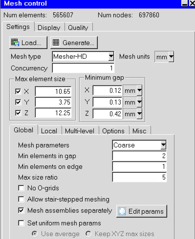
We can see that there is very significant decrease in the mesh count compared to previous generated mesh.
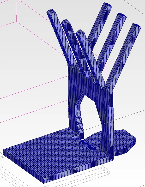
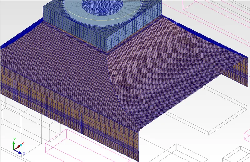
3) But we when inspect the mesh we can see that there are some irregularties in regions of the complex geometry gemotry components where mesh is not nicely and formed and not capture the component correctly. Examples of two components are shown below, -
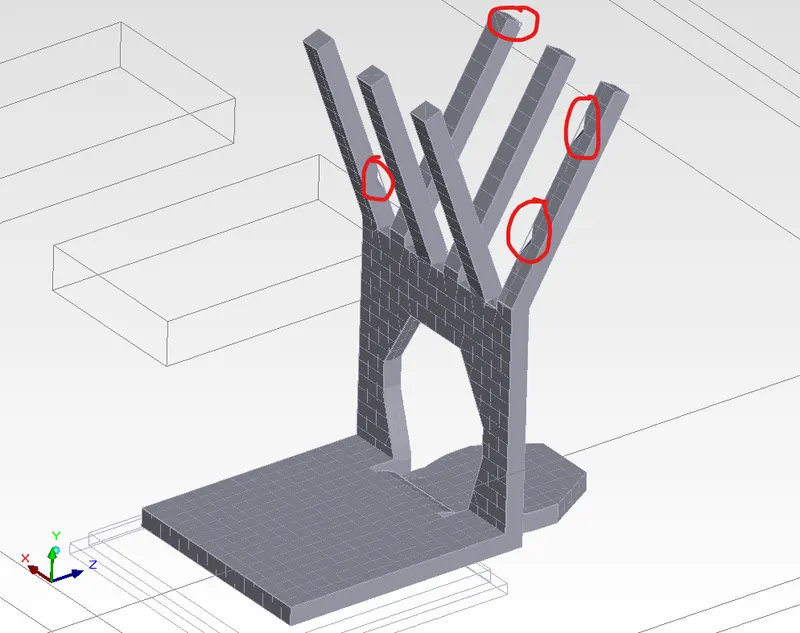
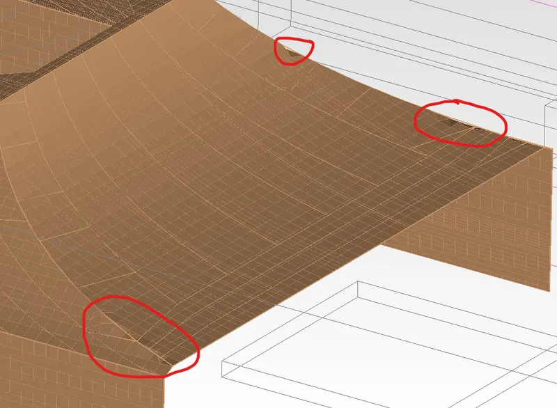
4) So Multi Level Meshing tool is being to make finer mesh to these components specifically with relative to other components and nearby regions.
Along with this setting we can also use set uniform mesh parameter with average setting, which will create uniform mesh cells on the region by averaging.
5) Mesh Quality Parameters
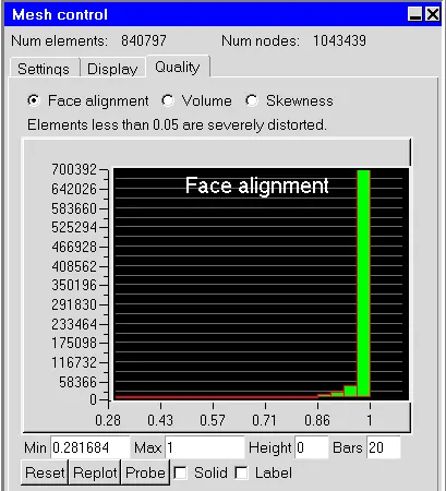
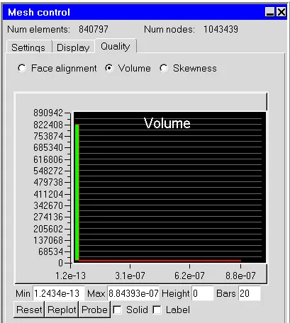
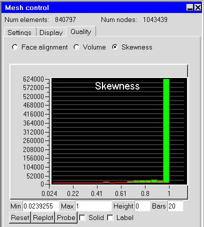
We can the mesh quality is very satisfied. 90% of the mesh cell are lying on good quality range.
CONCLUSION :
Hence, We have successfully generated mesh for the case geometry using multi-level and non-conformal meshing. We were able capture the complex geometry and surface bodies.