Week 4 -Wire Bending Challenge
WIRE BENDING
Aim
To model a wire bending system and determine strains and stresses on the wire
Theory
Wire forming is a method for applying force to change the contour of wire by bending, swaging, piercing, chamfering, shearing, or other techniques. The various techniques for wire forming can produce any type of shape, form, or configuration. The process starts with coiled wire that is straightened before being formed.
Common metals used for wire forming include steel, brass, stainless steel, copper, aluminum, and a variety of different alloys. The diameters of wires vary from 0.5 mm to 6.5 mm, or 1/64th of an inch to a quarter inch and can produce 2 and 3 dimensional wire forms.
Procedure
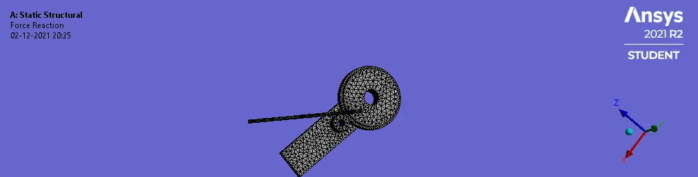
- Start a new static structural model in ansys and import the model
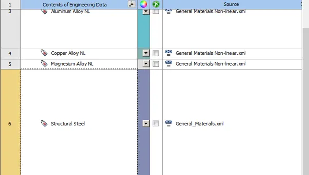
- Add the nonlinear materials of copper alloy, aluminium alloy and magnesium alloy located in non linear materials.
- Open this model in ansys mechanical.
- Check that the materials were properly assigned to the model, set wire material to copper alloy.
- Set the contact to rename based on definition and select the faces appropriately.
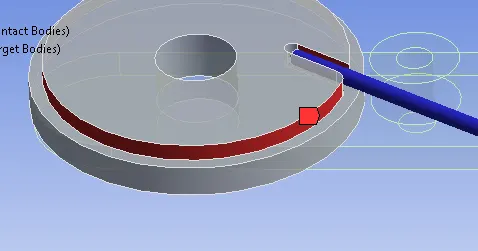
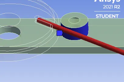
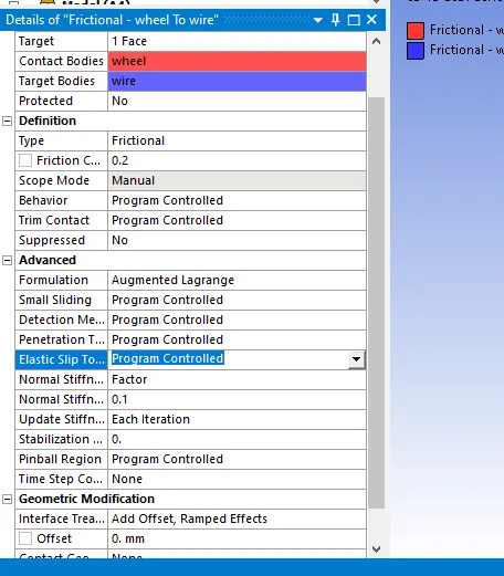
- Change the contacts to frictional and set friction coefficient to 0.2
- Change the contact properties as shown
- Create a Body-ground revolute joint as shown, (this is to define the rotational motion that will cause bending)
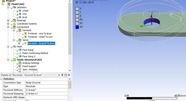
- Use the reference coordinate system to change the axis if it isn’t as shown in the above figure.
- In mesh, create a sizing group for the areas of interest and set mesh size to 2.2mm.
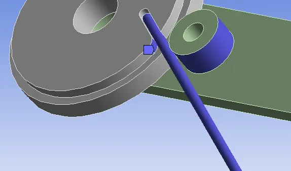
- Select all the parts using the body option and set element type to tetrahedron elements (this is to make sure elements are consistent and will transfer forces properly)
- Create a sphere of interest near the location of highest stresses as shown.This is to increase mesh refinement for higher accuracy in that area
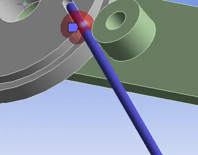
- Make sure to select a sufficiently high radius to cover your area of interest as force propogation outside that area may be improper due to mesh density differences.
- Set a fixed support to provide the required rigidity to the model.
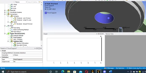
- Define the displacement of the sheet metal along the y axis, choose the opposite face shown as well.
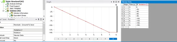
Analysis Settings
Set the analysis settings as shown.
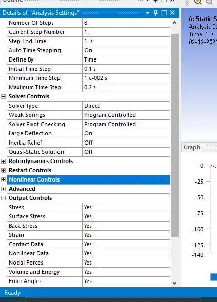
(set all the output controls to yes)
- For step 2-8
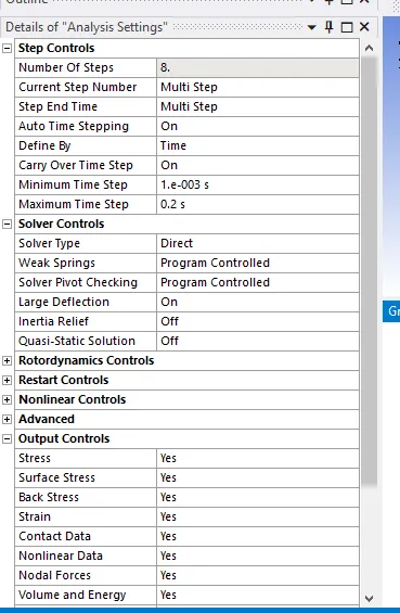
(if you get convergence issues due to timestep try reducing the timestep even further)
Set your output blocks as shown
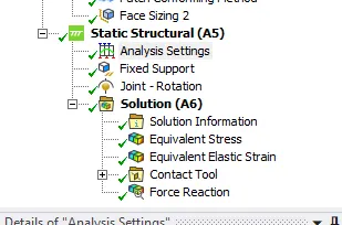
- The deformation and strain is just for the wire.
Post Processing
Sheet rolling
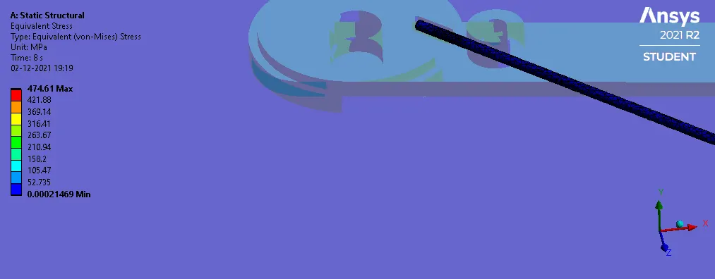
Tabulated Results
|
Material |
Copper |
Aluminium |
Magnesium |
|
Maximum Stress (MPa) |
656.3 |
441.45 |
474.61 |
|
Elastic Strain |
0.006048 |
0.0063 |
0.0106 |
|
Maximum Pressure on wire (MPa) |
502.32 |
350.46 |
334.25 |
It can be seen that the stresses and pressure experienced by the wire for each material is different, indicating that different amount of force is required to bend different wires due to their different resistances to bending.
This is crucial to take into account as it can increase the cost of machining and might make a solution unviable due to the high cost of manufacture.
Conclusion
Wire forming is a method for applying force to change the contour of wire by bending, swaging, piercing, chamfering, shearing, or other techniques. The various techniques for wire forming can produce any type of shape, form, or configuration. The process starts with coiled wire that is straightened before being formed.
In this project, a simple wire bending setup was modelled and run to determine the differences in stresses and strains experienced by the wire for different materials.