Week 4 -Wire Bending Challenge
1. Objective
We have to perform an analysis to simulate the bending of a wire using ANSYS. Wire has 3 different materials as Copper alloy NL, Aluminum alloy NL and Magnesium alloy NL. Then we need to identify equivalent stress, the equivalent strain on the wire.
2. Case setup and execution
- Change material of wire from engineering data sources
- Set formulation method to augmented Lagrange
- Change the mesh size settings and define the contact as per the definition and delete the first two default contacts.
- Change the contacts to frictional with a coefficient of friction of 0.2
- Change normal stiffness to a factor of 0.1
- Update stiffness for every iteration
- Change interface treatment to Add Offset, Ramped Effects
- Use face sizing where the contact face between wire, lever and wheel occurs
- Use element size of 2.2mm
- Then at the bend region of the curve use type as a sphere of influence by creating a new coordinate system that has an offset of X 3mm and Z by -3mm
- The radius of a sphere is 7mm and the element size is 0.8mm
- In Analysis settings, change the number of steps to 8
- For 1st step, the min time step is 1e-2s with an initial time step of 0.1s and a final time step of 0.2s
- Switch on large deflection and solver type to direct
- For time steps 2-8, the minimum time step is 1e-2s and the maximum time step is 1s with carryover time step turned on
- Define rotation for revolute joint by Rotation Z and tabular data
- Make sure the end part of the wire is fixed to avoid slipping the wire from the groove during simulation
- Check the maximum number of cores and clear generated data to avoid the simulation from starting at the previous endpoint.
3. Results of case 1
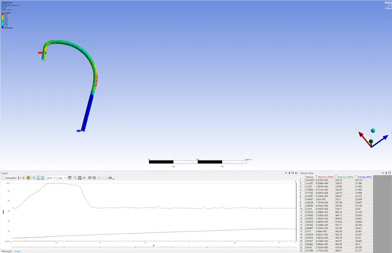
Fig 1 Equivalent stress on wire
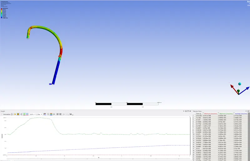
Fig 2 Equivalent strain on wire
4. Results of case 2
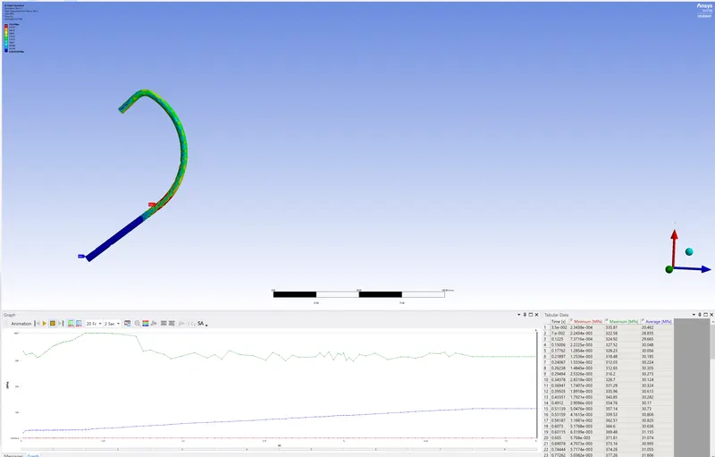
Fig 3 Equivalent stress on wire
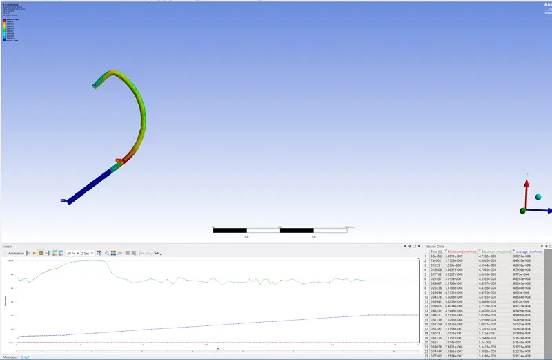
Fig 4 Equivalent strain on wire
5. Results of case 3
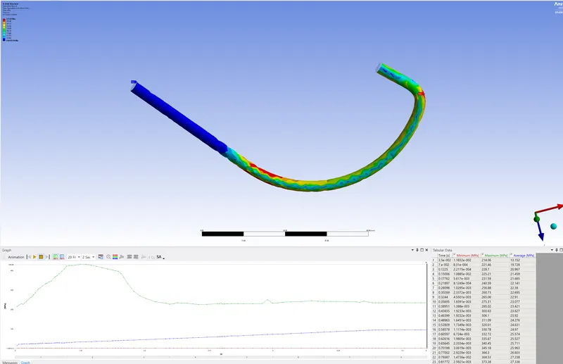
Fig 5 Equivalent stress on wire
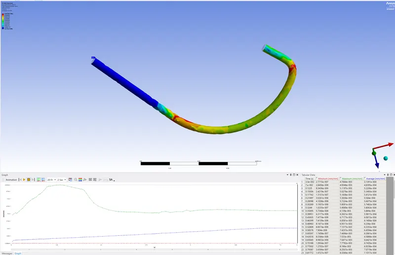
Fig 6 Equivalent strain on wire
6. Results, Conclusion and report presentation
For case 1,
| equivalent stress | 325.56 MPa |
| equivalent strain | 2.9784e-3 |
For case 2,
| equivalent stress | 314.4 MPa |
| equivalent strain | 4.5202e-3 |
For case 3,
| equivalent stress | 233.42 MPa |
| equivalent strain | 5.5021e-3 |
As seen from the above figures, the maximum value of elastic stress on wire occurs in case 1 followed by cases 2 and 3. However, maximum equivalent stress on wire occurs in case 3 followed by base 2 and case 1.If we look at Fig 1, maximum equivalent Von-mises stress occurs at the bends. Same scenario is reflected in Fig 2 for equivalent strain. This is due to increased stress generation in those areas. It is more concentrated towards outer section of wire compared to inner one. Same scenario occurs in all other cases. One of the main reasons for stress concentration at edges is the type of mesh which is tetrahedrons that are more stiff compared to quads. Also the bending moment/reaction force will be highest in these regions.
7. Simulation files
Files are attached. As the file size is large, I have uploaded in drive
https://drive.google.com/file/d/1qOCYw6z4C4bAqJ0OKKu6xIibqxNDD4F9/view?usp=sharing
https://drive.google.com/file/d/1qQnYxNnOq7skdNTrLNUe1qLblm68Bl4W/view?usp=sharing
https://drive.google.com/file/d/1YLy5EeX5nZ3cPtr1bOVgWLZaBCfQ_ySz/view?usp=sharing