Week 4 -Wire Bending Challenge
WIRE BENDING
AIM:
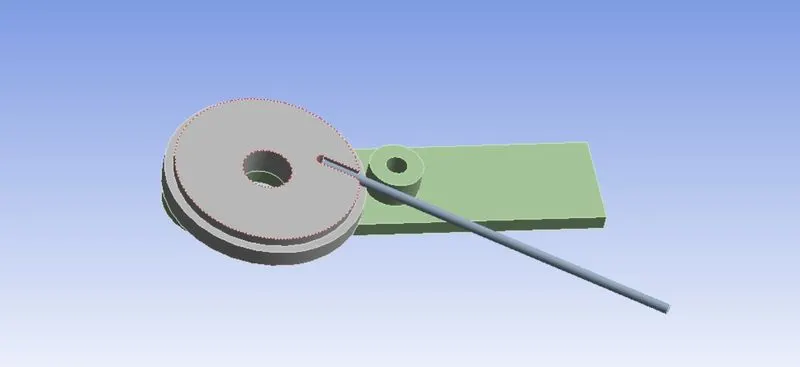
To Analyse and simulate the bending of wire using three different materials for three different cases, using a wheel and a lever.
MODEL :
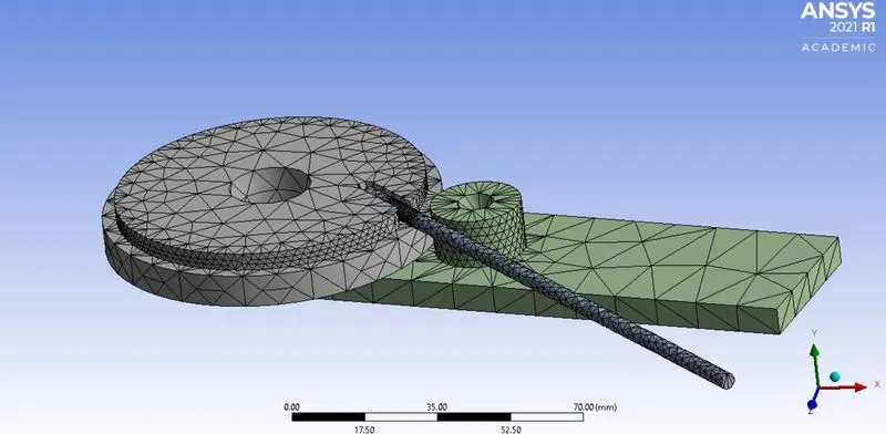
The model consists of one wheel and lever attached with the other side of the wheel and the wire .
MATERIALS USED:
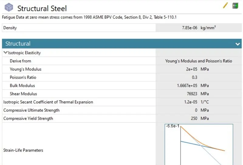
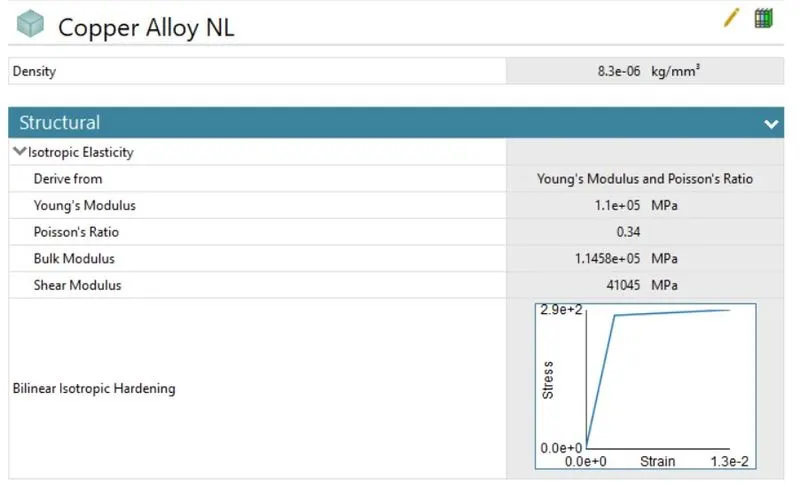
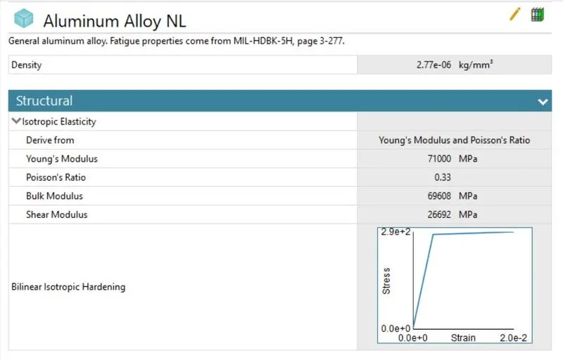
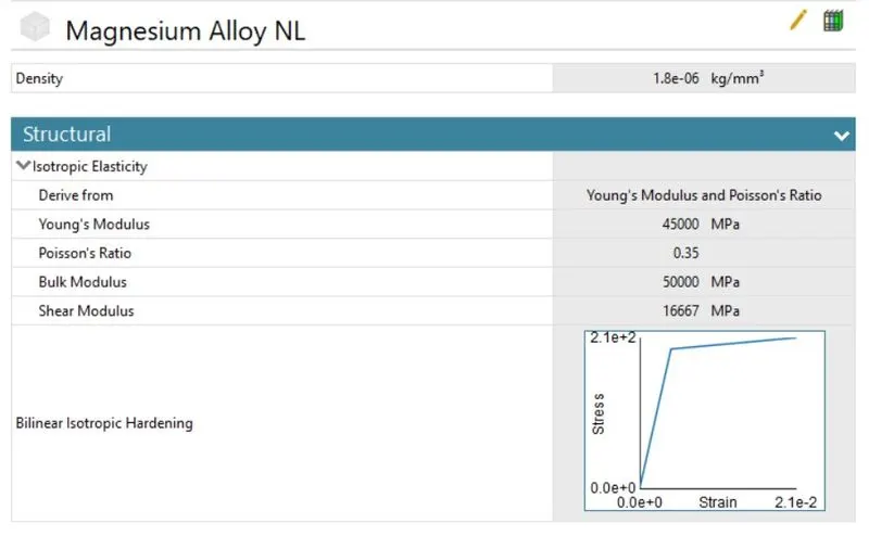
The simulation consists of 4 different materials entirely for the apparatus , for the wire it differs for three materials and for the wheel and the lever it is fixed with the structural steel .
STRUCTURAL STEEL :
COPPER ALLOY NL :
ALUMINIUM ALLOY NL :
MAGNESSIUM ALLOY NL :
CONNECTIONS:
The default contact pairs has been deleted and we are inserting a manual contact region to define our required contact pairs
CONTACTS:
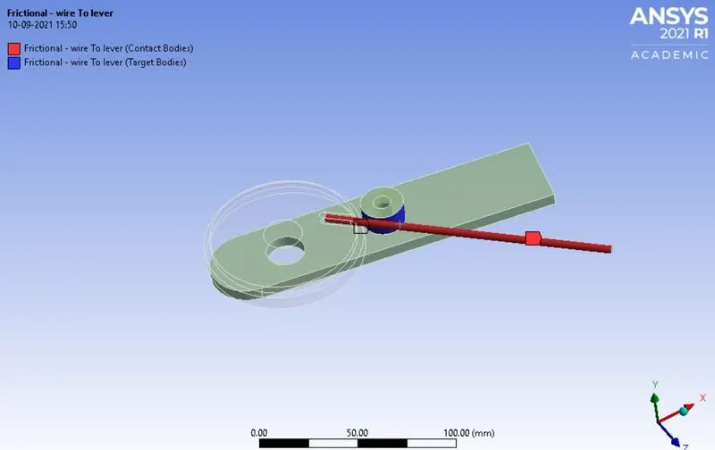
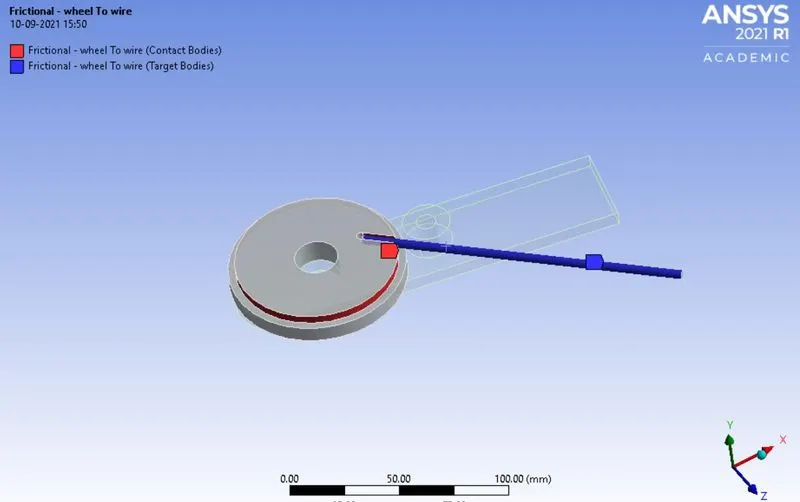
The type of contacts we are using here is frictional contacts , and the co-efficient of fricition is set to 0.2 and the type of behaviour of the contacts is set to auto-asymmetric .
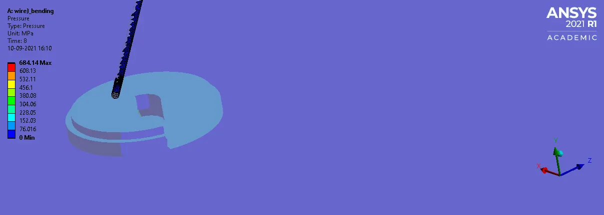
CONTACT 1 : WIRE TO LEVER
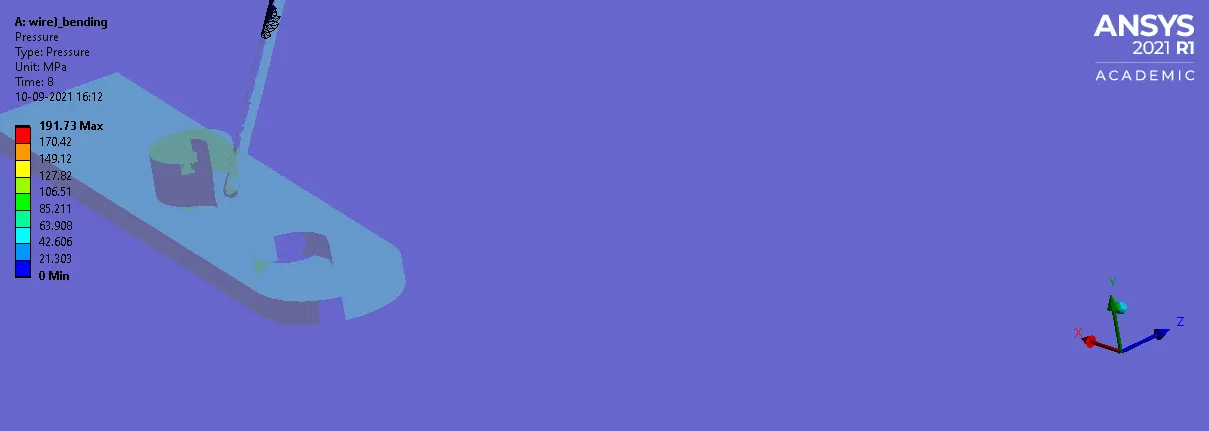
CONTACT 2 : WHEEL TO WIRE
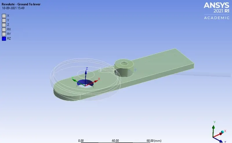
JOINTS:
Joints here are used to define the load to be given in order to carry on the simulation and the type of joint given here is revolute joint and it is set to the the lever , where it rotates to provide the necessary moment to bend the wire .
MESH :
We are introducing tetrahedron method to the model for generating the mesh and the patch conforming method program has been used to generate the mesh , we are giving the grid dependency test to allot a default value for the mesh size and we are particularly concerned on some faces of the model where the loads act vigourosuly we are given a 2.2 mm mesh size for the particular faces and the certain face of the wire we are introducing sphere of influence technique to generate mesh at the particular face where the wire experiences more stress , the mesh size for the sphere of influence method is 0.7 mm .
ANALYSIS SETTINGS:
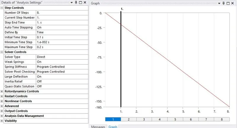
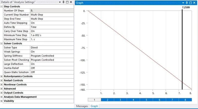
The analysis has been carried out under 8 steps where we are implementing loads and the time steps respectively .
FIXED SUPPORTS:
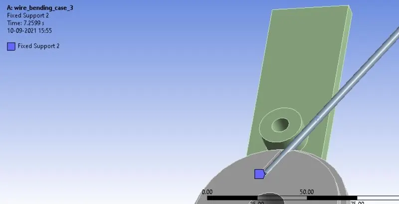
These fixed supports are given to make a support rigid .
FIXED SUPPORT 1: WHEEL
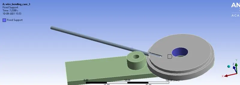
FIXED SUPPORT 2: WIRE
JOINT LOAD :

CASE 1 : COPPER ALLOY NL
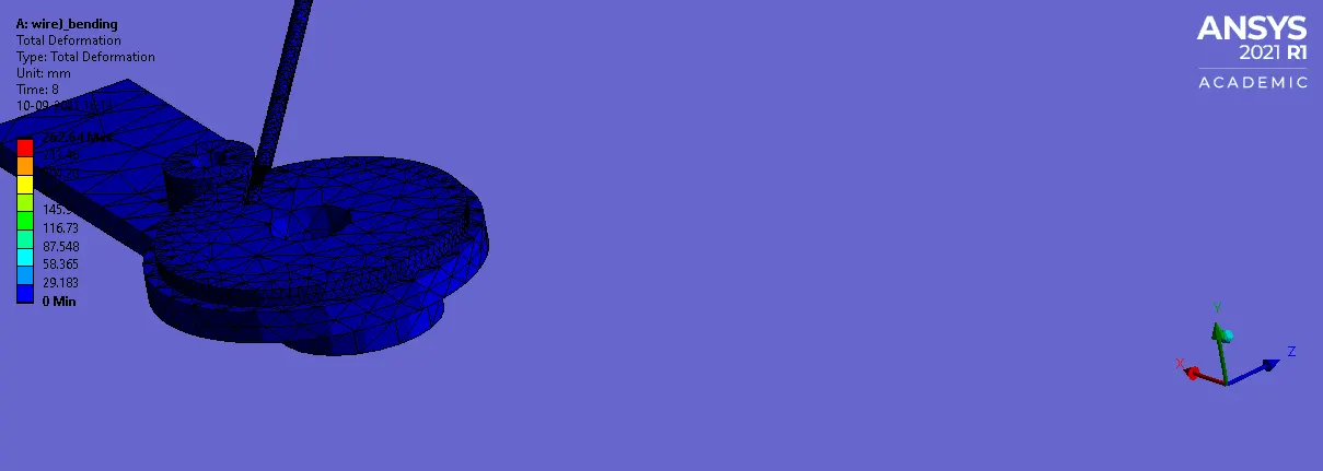
TOTAL DEFORMATION :
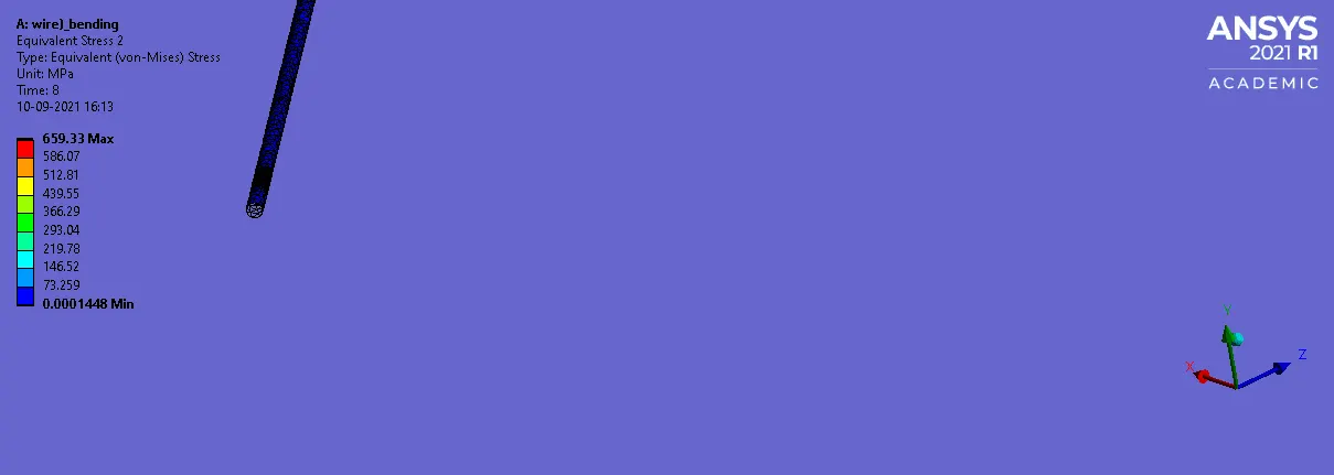
EQUIVALENT STRESS WIRE :
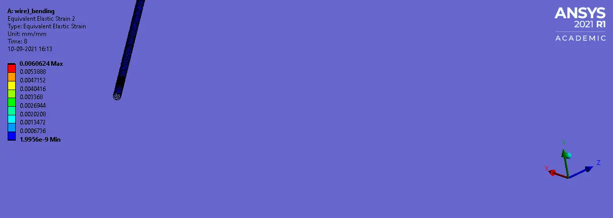
EQUIVALENT STRAIN WIRE :
CONTACT PRESSURE:
1: CONTACT 1 :
2: CONTACT 2 :
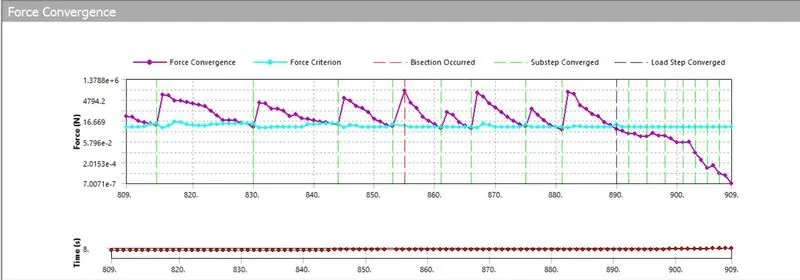
FORCE CONVERGENCE :
CASE 2 : ALUMINIUM ALLOY NL
TOTAL DEFORMATION :

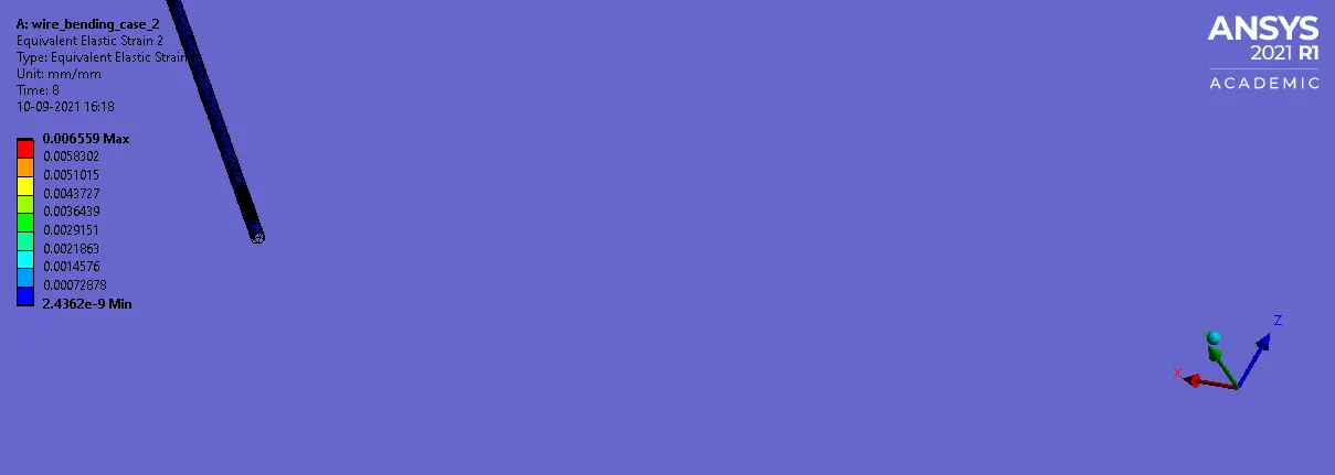
EQUIVALENT STRAIN WIRE :
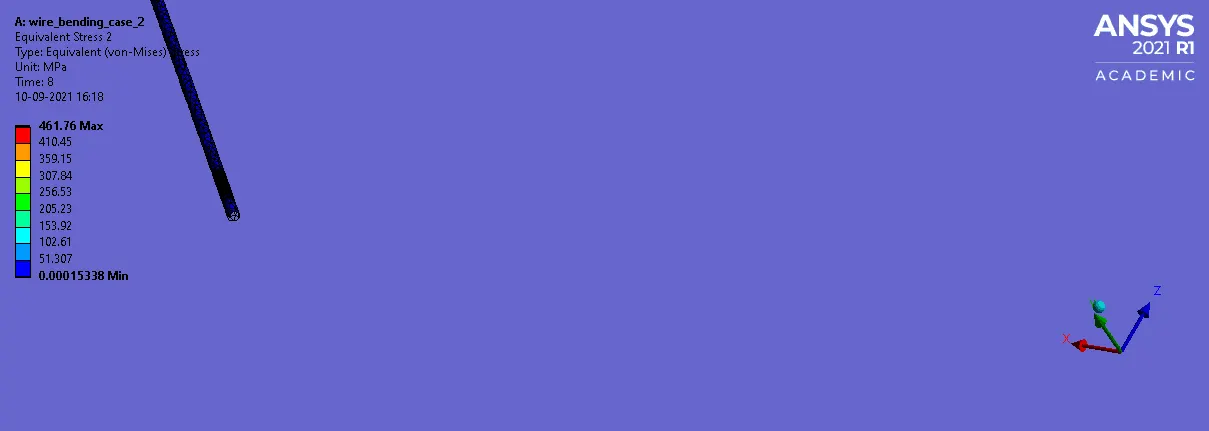
EQUIVALENT STRESS WIRE :
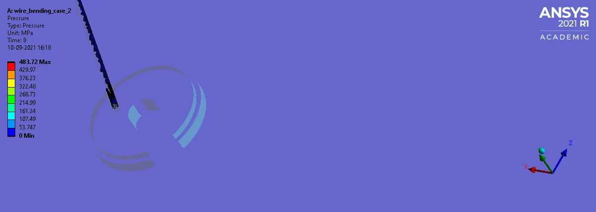
CONTACT PRESSURE:
1: CONTACT 1 :
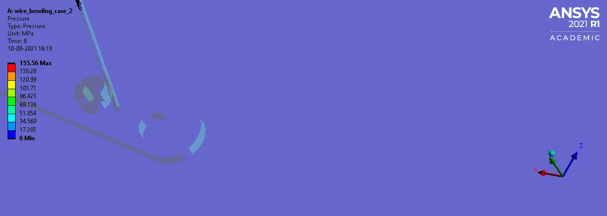
2: CONTACT 2 :
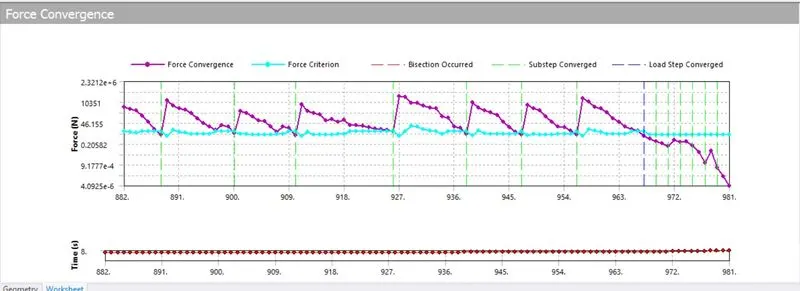
FORCE CONVERGENCE :
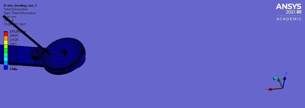
CASE 3 : MAGNESSIUM ALLOY NL
TOTAL DEFORMATION :
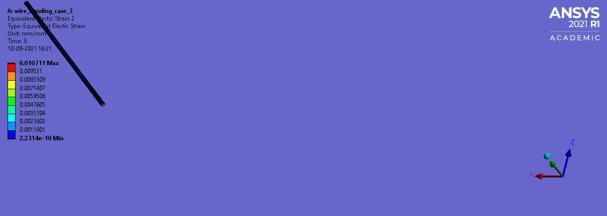
EQUIVALENT STRAIN WIRE :
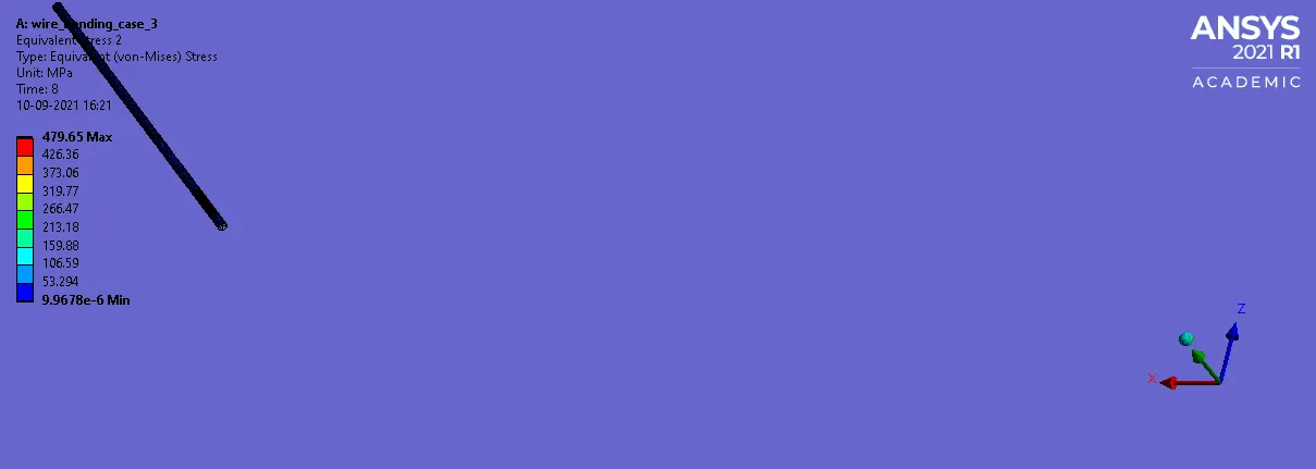
EQUIVALENT STRESS WIRE :
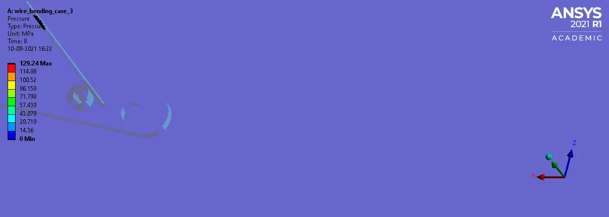
CONTACT PRESSURE:
1: CONTACT 1 :
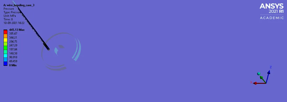
2: CONTACT 2 :
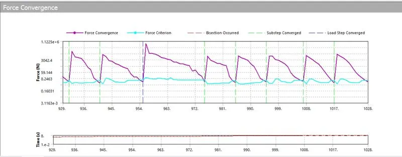
FORCE CONVERGENCE :
RESULT :
FROM THE ABOVE SIMULATIONS WE COME TO CONCLUDE THAT THE WIRE WITH COPPER ALLOY NON-LINEAR PROPERTIES HAD WITHSTANDED HIGH STRESS VALUE THAN THE OTHER TWO MATERIALS
WHEREAS THE MAGNESSIUM ALLOY NL HAD EXPERIENCED HIGH STRESS VALUE THAN THE ALUMINIUM ALLOY NL , COPPER ALLOY HAS BEEN RECOMMENDED AS IT WITHSTANDS HIGH STRESS VALUE AND ALSO IT CAN PROVIDE HIGHER LIFE THAN THE OTHER TWO MATERIALS .