Week 4 -Wire Bending Challenge
WIRE BENDING SIMULATION
OBJECTIVE
To perform analysis on Wire bending operation in ANSYS by assigning different materials for the wire namely,
- Copper Alloy (Non Linear),
- Aluminium Alloy (Non Linear)
- Magnesium Alloy ( Non Linear)
And compare the results of Equivalent Stress and Equivalent Strain on the wire and present the conclusion.
MODEL SETUP
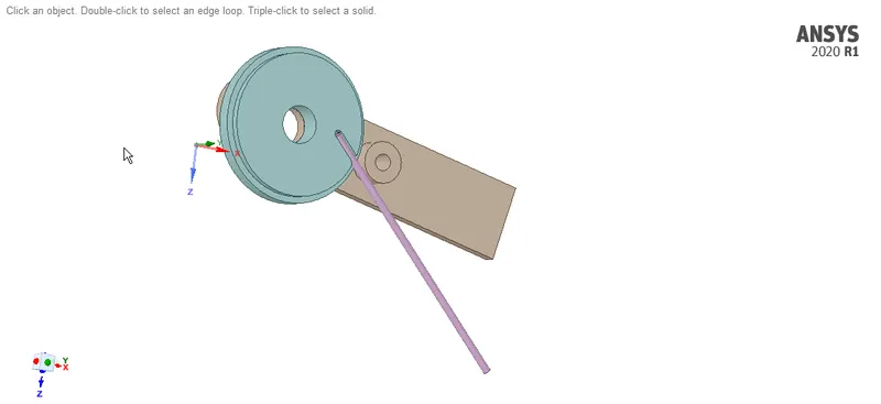
The 3D model of the setup is imported into ANSYS Space Claim. Check for any abnormalities in the Geometry.
MATERIAL ASSINGMENT:
- Structural Steel is assigned for the Lever and the Wheel
- Cu Alloy NL, Mg Alloy NL and Al Alloy NL are assigned for the wire individually and analysis is done
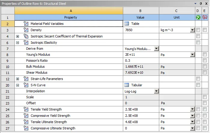
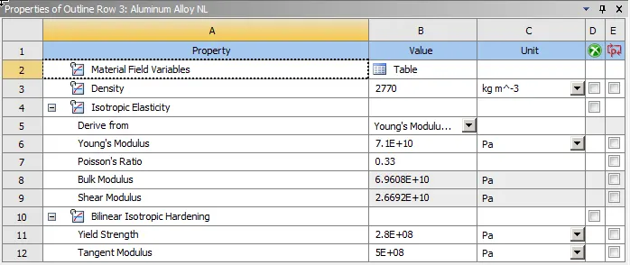
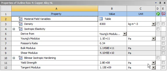
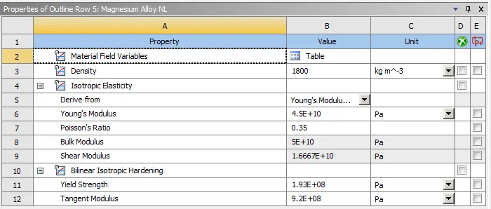
The properties of various materials used are shown below
- Structural Steel :
- Al Alloy NL:
- Cu Alloy NL:
- Mg Alloy NL:
CONTACTS DEFINITION:
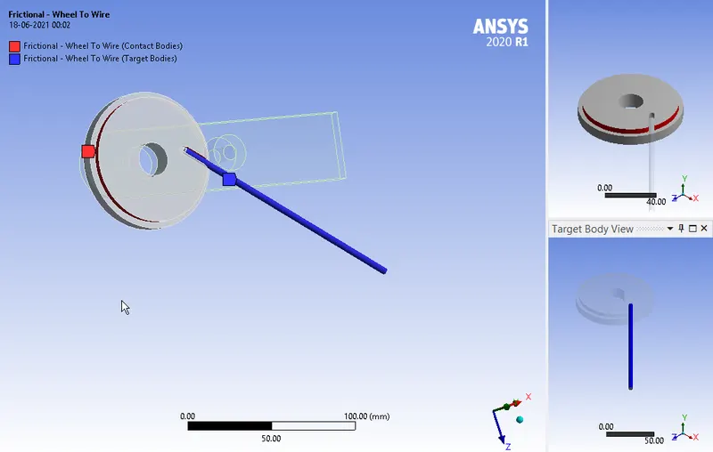
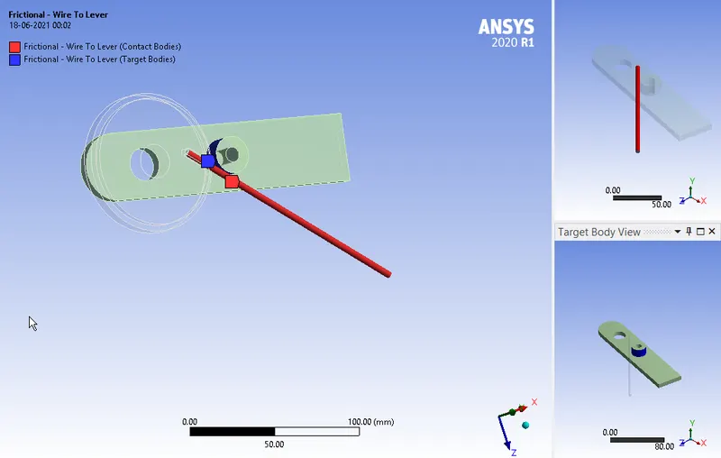
We need to define two contact regions for this model.
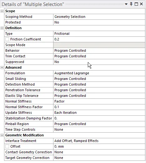
Frictional contact of 0.2 is selected between the
- The wire and outer surface of the wheel which will be in contact with that of wire while bending
- The wire and the Surface of the Lever which will be in contact with that of wire while bending
The settings are as shown below
JOINT DEFINITION:
We need to define joints for the Lever
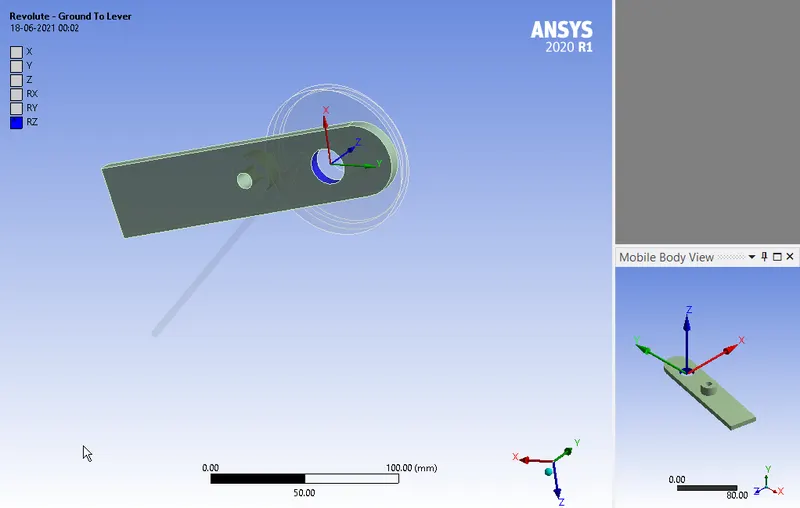
- A Revolute joint is assigned to the Lever :
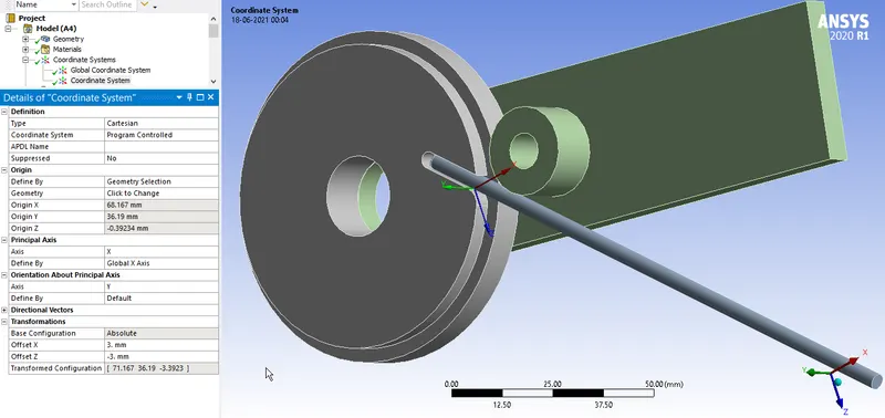
Make sure the reference co-ordinate system assigned to the joint is as shown
MESHING:
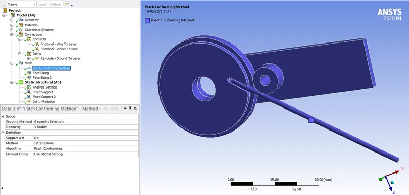
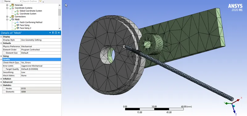
The meshing is done as follows,
- Wire, Lever and Wheel are meshed with Tetrahedron elements with Patch Confirming Algorithm
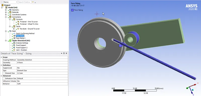
- A face sizing of element size 2.2 mm is selected for the
- Surface of the wire
- The Portion (face) of the Wheel where the wire contacts initially during bending
- The surface of the lever which is in contact with that of wire during bending
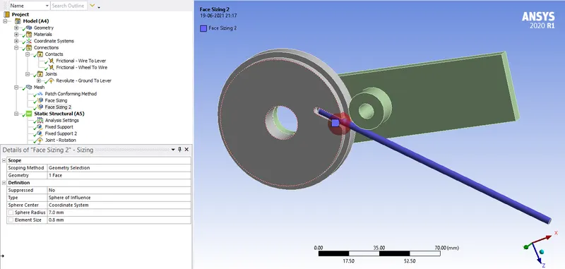
- A face sizing of element size 0.8 mm is selected for the Wire
As stress developed is more at the wheel where wire contact initially during bending, a co-ordinate system is created at that area, and a Sphere of Influence type is assigned with Sphere radius 7 mm at that portion and element size of 0.8 mm is assigned to analyse accurately.
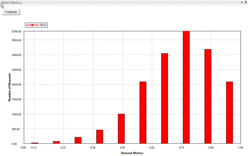
FINAL MESH AND MESHING QUALITY :
ANALYSIS SETTINGS:
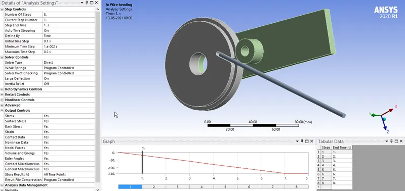
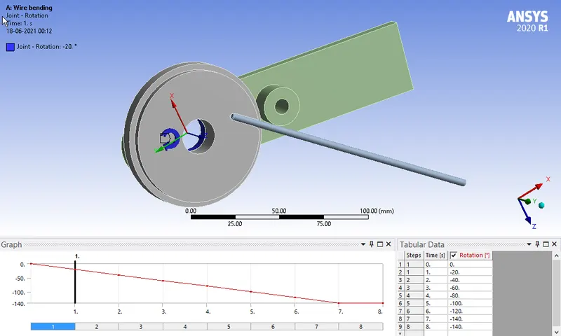
Now, the simulation is run for 8 steps. The following settings are modified
Auto Time stepping is set to ON and Time step values are assigned as shown below.
Solver Type is set to Direct
Weak springs are set to Program Controlled
The Large deflection is set to ON.
Other settings are as shown below
BOUNDARY CONDITIONS:
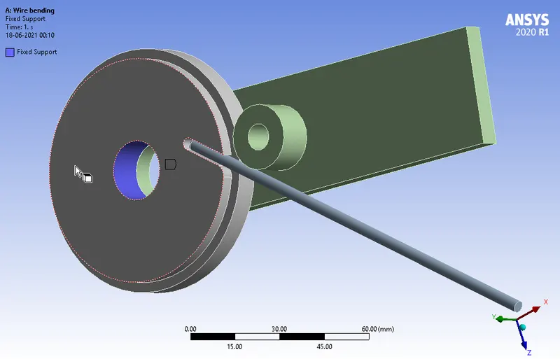
The boundary condition for this model are
- A fixed support for the Wheel :
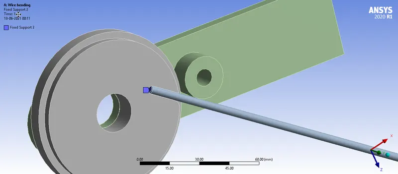
- A fixed support for the end face of the Wire :
This is done to avoid slipping of the wire during bending operation
- A Rotational Joint load is assigned for the lever:
RESULTS:
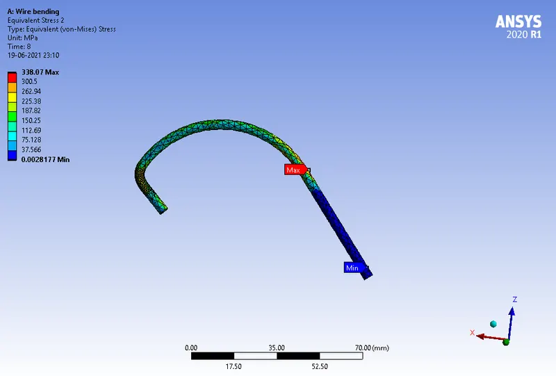
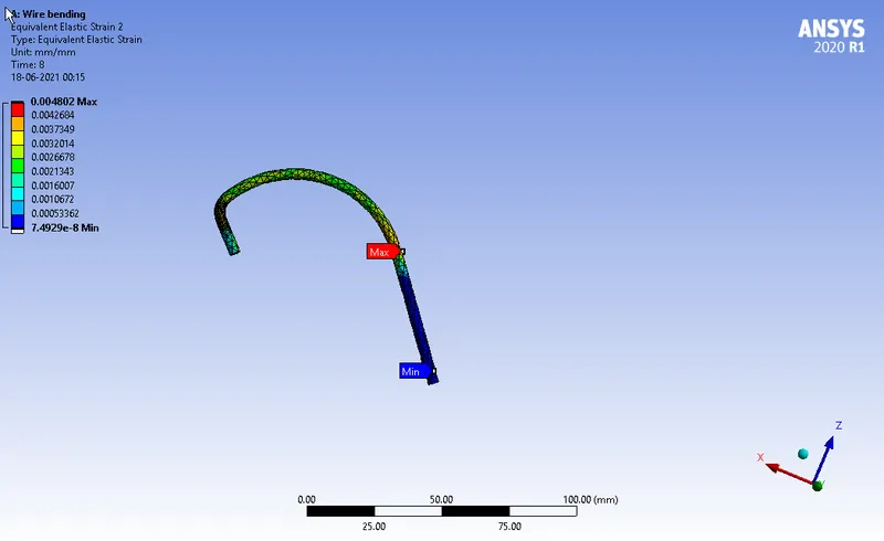
CASE 1: Al Alloy NL as the material for Wire
- Equivalent Stress of the Frame:
- Equivalent Elastic Strain of the Frame:
CASE 2: Cu Alloy NL as the material for Wire
- Equivalent Stress of the Frame:
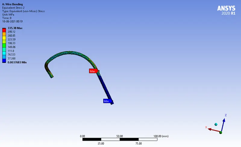
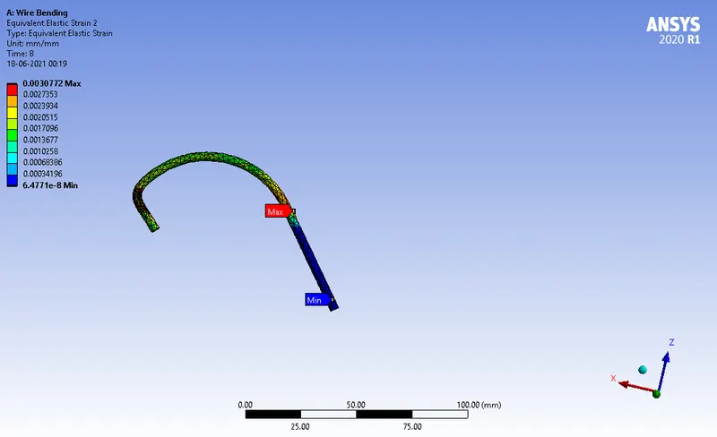
- Equivalent Elastic Strain of the Frame:
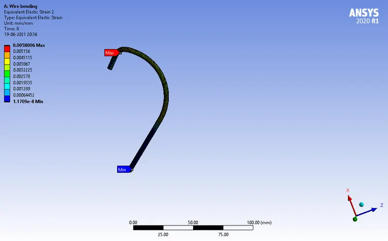
CASE 3: Mg Alloy NL as the material for Wire
- Equivalent Stress of the Frame:
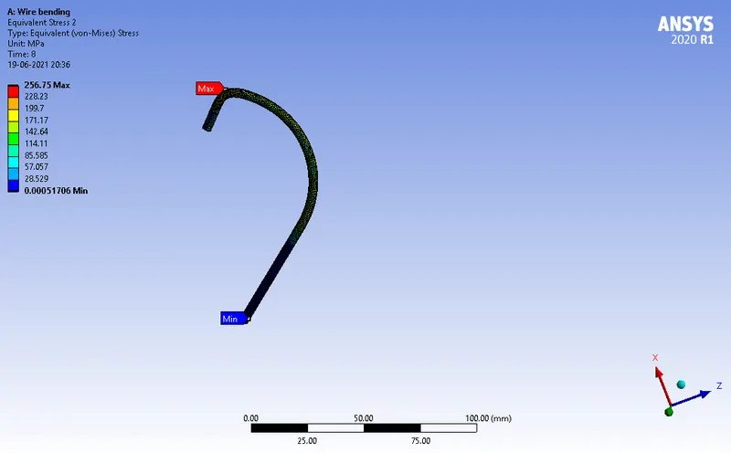
- Equivalent Elastic Strain of the Frame:
CONCLUSION:
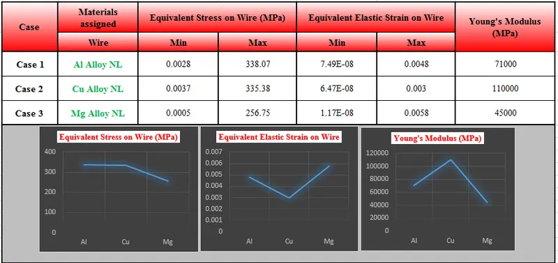
From the results, it can be inferred that
- Equivalent Stress is maximum for Al Alloy and almost same for Cu Alloy, followed by Mg Alloy because Young’s Modulus is higher for Al and Cu alloy and hence it exhibits high stiffness behaviour, which induces more stress on wire to deform.
- Equivalent Elastic strain is minimum for Cu Alloy and almost same for Al Alloy, followed by Mg Alloy because Young’s Modulus is higher for Cu and Al alloy and hence it exhibits high stiffness behaviour, which leads to lower strain on Al and Cu Alloy
The simulation files are attached below