Week 4 -Wire Bending Challenge
SIMULATION OF WIRE BENDING USING ANSYS WORKBENCH
OBJECTIVE
1. To simulate bending of wire for different cases of wire material,
- Case-1: Copper Alloy NL
- Case-2: Aluminium Alloy NL
- Case-3: Magnesium Alloy NL
2. To find out Equivalent stress and Equivalent strain developed in wire for each case and compare the results.
1. THEORY
1.1 Wire Bending:
The process of wire bending involves using mechanical force to push wire against a die, forcing the wire to conform to the shape of the die. Often, it is held firmly in place while the end is rotated and rolled around the die. Other forms of processing including pushing stock through rollers that bend it into a simple curve.
Rotary draw bending (RDB) is a precise technology, since it bends using tooling or "die sets" which have a constant centre line radius, alternatively indicated as mean bending radius. Rotary draw benders can be programmable to store multiple bend jobs with varying degrees of bending. The rotary-draw-bending method is a complex physical process with multi-factor interactive effects and is one of the advanced tube or wire forming processes with high efficiency, high forming precision, low consumption and good flexibility for bending angle changes. However, it may cause a wrinkling phenomenon, over thinning and cross-section distortion if the process parameters are inappropriate. Wrinkles propagate, but in some cases, localize in a finite zone and lead to failure.
Rotary draw benders create aesthetically pleasing bends when the right tooling is matched to the application. CNC rotary draw bending machines can be very complex and use sophisticated tooling to produce severe bends with high quality requirements. Rotary draw benders are the most popular machines for use in bending tube, pipe and wires for applications like: handrails, frames, motor vehicle roll cages, handles, light fittings, hanger hooks, key chains, refrigerator rack, stainless steel fruit baskets, and other metal wire and strip forming and bending.
2. ANALYSIS SETUP
2.1 Geometry:
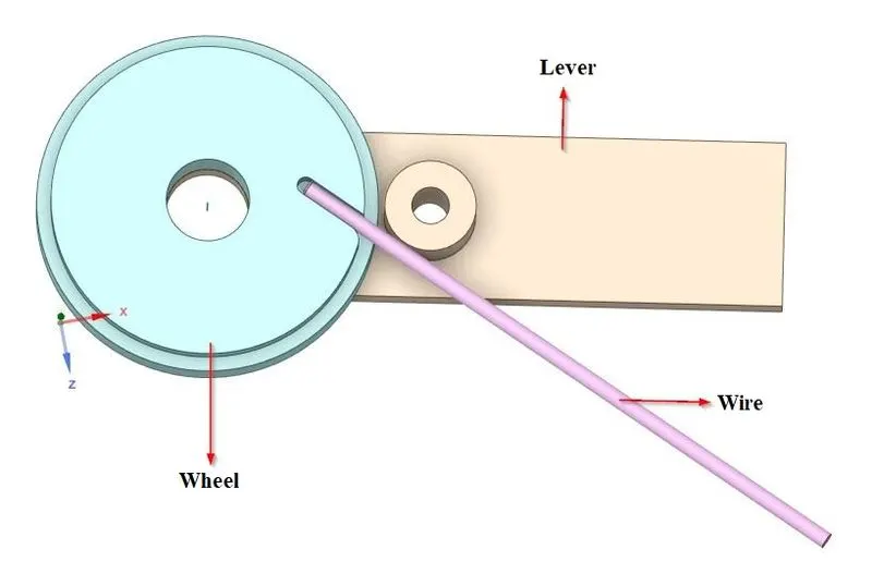
Fig.2.1 3D model of wire bending setup.
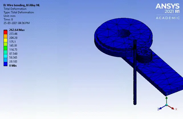
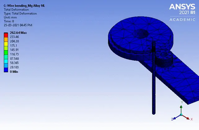
The given 3D model of wire bending setup assembly is imported into SpaceClaim. It consists of a wheel, lever and wire. The wire is held in the slot of the wheel and it is made to bend, forcing the wire to conform to the shape of the wheel using the rotating lever.
2.2 Material Properties:
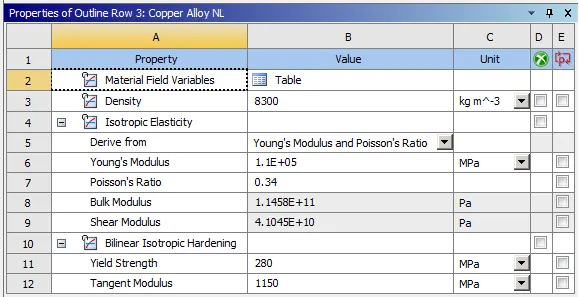
a. Copper Alloy NL.
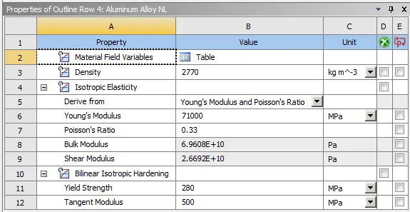
b. Aluminum Alloy NL.
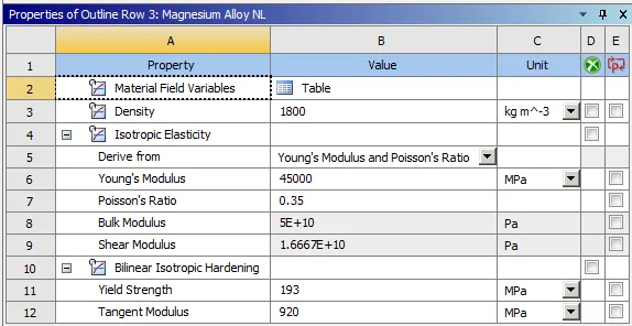
c. Magnesium Alloy NL
Fig.2.2 Material property details of wire.
The following materials are assigned for wire for each case,
- Case-1: Copper Alloy NL
- Case-2: Aluminium Alloy NL
- Case-3: Magnesium Alloy NL
Note: The analysis setup of only case-1 is demonstrated.
2.3 Connection Details:
2.3.1 Contact details:
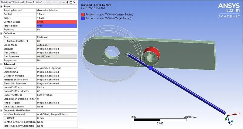
a. Contact between lever and wire.
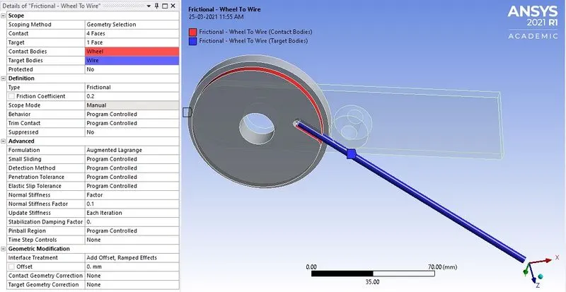
b. Contact between wheel and wire.
Fig.2.3.1 Contact details of wire bending.
Contact between, (a) Lever (contact body) and wire (target body), (b) Wheel (contact body) and wire (target body) are assigned as frictional contact with coefficient of friction = 0.2. The formulation type of contact is set as ‘Augmented Lagrange’ and normal stiffness value is inputted as 0.1 factor with update stiffness set to as ‘each iteration’. The interface treatment is set as ‘Add Offset, Ramped Effects’.
2.3.2 Joint Details:
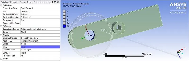
Fig.2.3.2 Joint details of wire bending,
The revolute type of joint is assigned for lever with connection type being body-ground, since only rotation is specified along Z-axis.
2.4 Meshing:
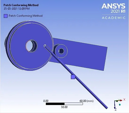
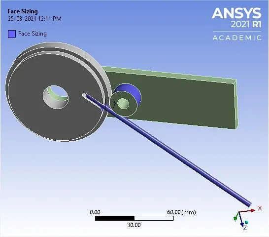
a. Patch conforming method (tetrahedron). b. Face sizing of contact region of lever and whole wire.
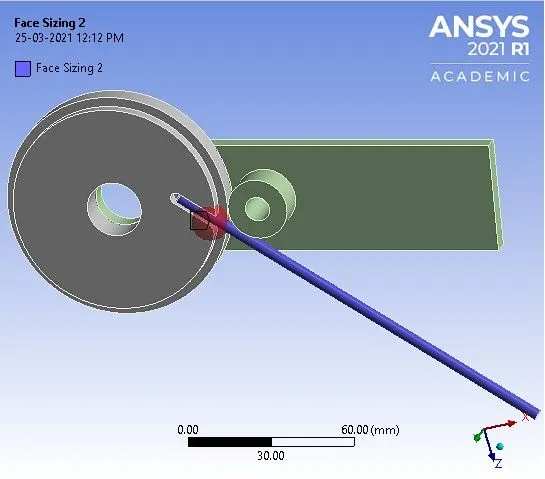
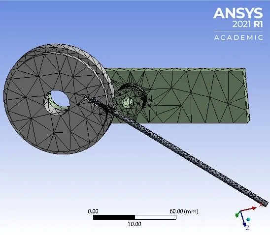
c. Face sizing of contact region of wire and wheel. d. Meshed model.
Fig.2.4 Meshing details of wire bending.
The element generated in meshing the model is ensured as tetrahedron elements by using patch conforming method. The mesh size of the contact regions of lever and wire is refined to 2 mm by using face sizing option. The mesh size of the contact region of wire and the curved region of wheel is refined to 0.8 mm using face sizing option with sphere centre being created using user defined coordinate system and sphere of influence radius being 7 mm. The total number of nodes and elements generated are 9067 and 4554 respectively.
Note: The academic version of software has the problem size limit of 128k nodes or elements.
2.5 Boundary Conditions:
2.5.1 Analysis settings:
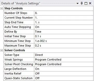
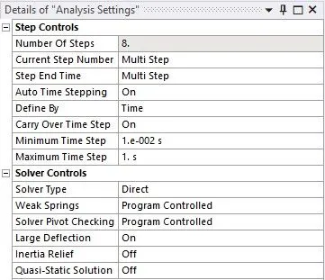
a. Analysis setting for step 1. b. Analysis setting for step 2 to step 8.
Fig.2.5.1 Analysis settings.
In the analysis settings the number of steps considered is 8 and auto time stepping is set to ‘On’ which is defined by ‘time’. For step 1, the initial, minimum and maximum time step is considered as 0.1s, 1e-2s and 0.2s respectively. For step 2 to step 8, the minimum and maximum time step is 1e-2s and 1s respectively. In the solver controls, solver type is chosen as ‘Direct’ and large deflection is set to ‘On’. Under the output controls, all the results are set to ‘Yes’.
2.5.2 Boundary condition for wire bending:
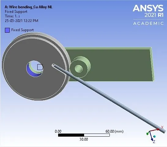
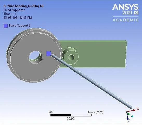
a. Fixed support.
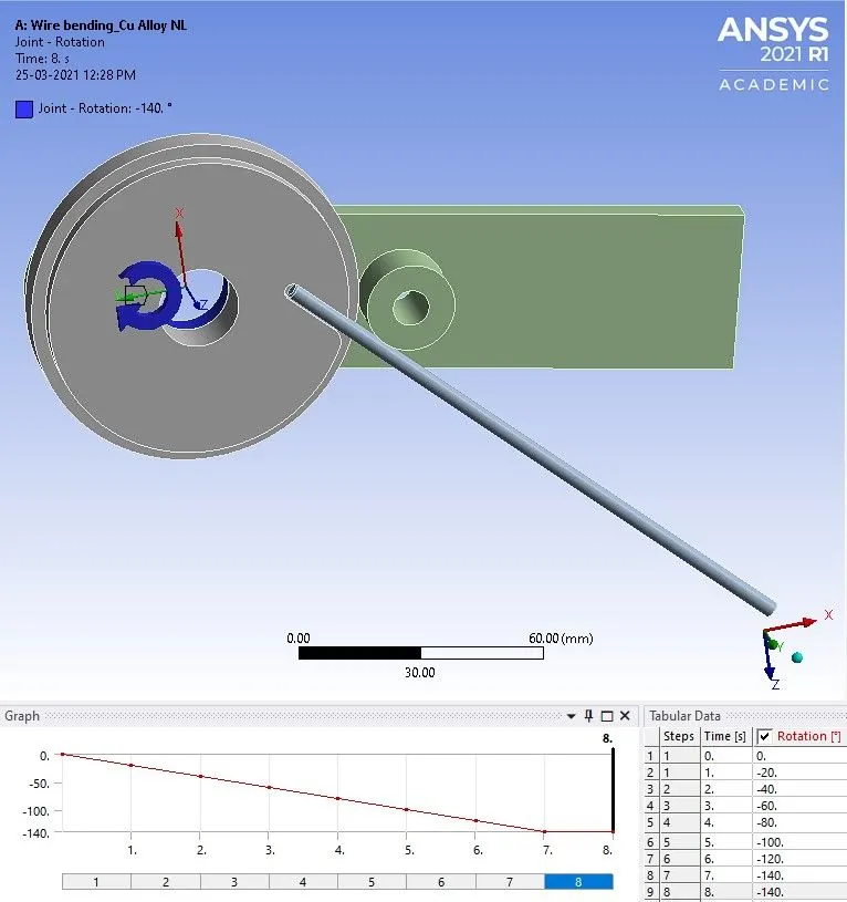
b. Joint load applied to lever along Z-axis.
Fig.2.5.2 Boundary conditions for wire bending.
Since, the wheel is stationary and to avoid slippage of wire while bending, fixed support is assigned to the surface of the wheel and wire as shown in fig. 2.5.2 a. In order to bend wire, the lever is made to rotate in clockwise direction from 00 to 1400, with an increment of 200 in each step.
3. RESULTS AND DISCUSSIONS
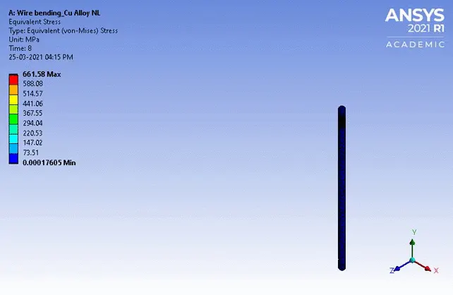
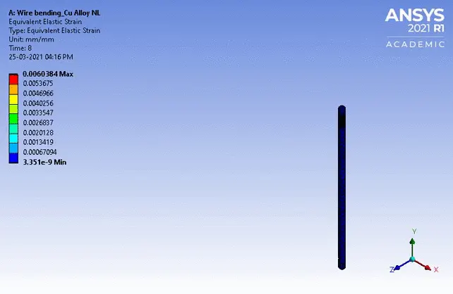
3.1 Case-1: Wire material; Copper Alloy NL.
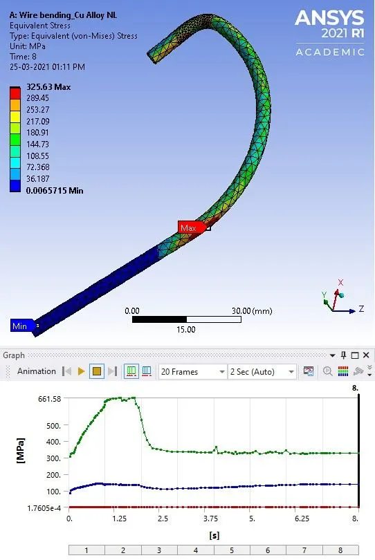
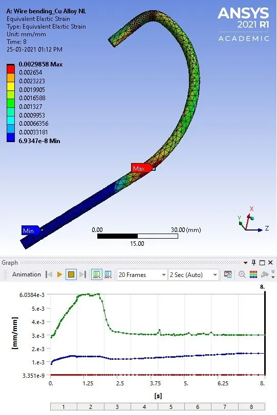
a. Equivalent (v-m) Stress. b. Equivalent Elastic Strain
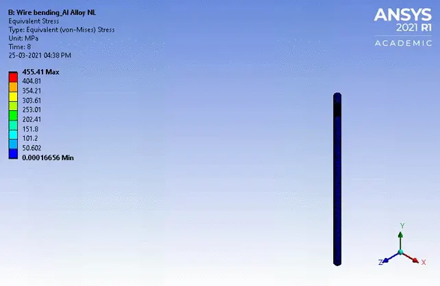
3.2 Case-2: Wire material; Aluminum Alloy NL.
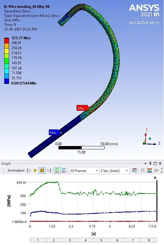
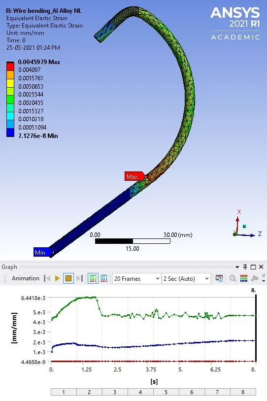
a. Equivalent (v-m) Stress. b. Equivalent Elastic Strain.
3.3 Case-3: Wire material; Magnesium Alloy NL.
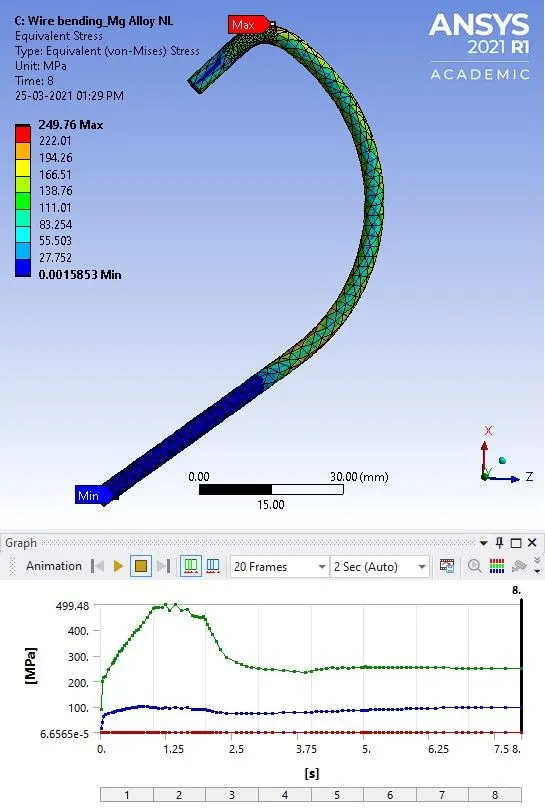
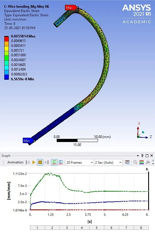
a. Equivalent (v-m) Stress. b. Equivalent Elastic Strain.
3.4 Comparison of Results:
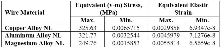
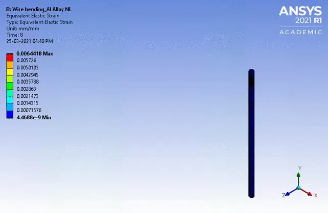
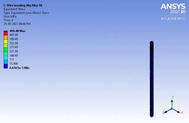
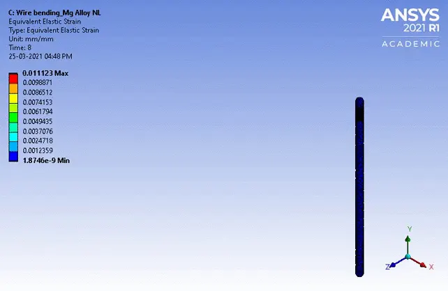
During the initial process of bending, the sharp bend of wire is experiencing maximum stress and strain. The results tabulated are pertaining to the step 8 (after bending).
From table, it is observed that the maximum v-m stress developed in wire material of magnesium alloy NL is least compared to other wire materials. For all the three cases of wire material the maximum v-m stress developed is more than its yield strength value, hence it undergoes plastic deformation and conforms to the shape of the wheel while bending. The maximum equivalent elastic strain developed in wire material of copper alloy NL is least compared to other wire materials which indicates that it is least deformed, hence it is preferred wire material among the given wire materials.
4. ANIMATION OF RESULTS:
4.1 Case-1: Wire material; Copper Alloy NL.
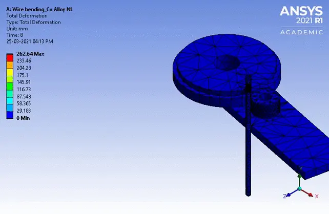
a. Total Deformation.
b. Equivalent (v-m) Stress.
c. Equivalent Elastic Strain
4.2 Case-2: Wire material; Aluminum Alloy NL.
a. Total Deformation.
b. Equivalent (v-m) Stress.
c. Equivalent Elastic Strain
4.3 Case-3: Wire material; Magnesium Alloy NL.
a. Total Deformation.
b. Equivalent (v-m) Stress.
c. Equivalent Elastic Strain
CONCLUSION
1. Simulation of bending of wire was carried out successfully for the following cases of wire material,
- Case-1: Copper Alloy NL
- Case-2: Aluminium Alloy NL
- Case-3: Magnesium Alloy NL
2. The maximum Equivalent (v-m) stress developed in Magnesium Alloy NL wire material is least compared to other wire materials.
3. For all the three cases of wire material the maximum v-m stress developed is more than its yield strength value, hence it undergoes plastic deformation and conforms to the shape of the wheel while bending.
4. The maximum Equivalent strain developed in Copper Alloy NL wire material is least compared to other wire materials. Hence, it is least deformed and preferred choice of material among the given wire materials.