Week 4 -Wire Bending Challenge
OBJECTIVE:-
In this challenge we have to simulate an analysis to perform the bending of wire in ANSYS. For this challenge we have to perform the simulation for 3 different materials,
- Copper alloy Non linear
- Aluminium alloy Non linear
- Magnesium alloy Non linear.
PROCEDURE FOLLOWED:-
Starting from create a new static structural, and add materials from add engineering data. We have to add 3 different materials for 3 different cases. The materials are:-
- Copper alloy non linear
- Aluminium alloy non linear
- Magnesium alloy non linear.
After adding the engineering data, import the geometry provided. Check for any errors by opening it in Space-claim. If all fine close spacecliam and update the model in Mechanical workbench. Open the model in mechanical workbench, and start from renaming the geometry. The names assigned in mymodel are
- Wheel
- Wire
- Lever
After the naming of the components, assign material copper alloy/Aluminium alloy/Magnesium alloy{Non-linear} to wire and the rest of the components must be assigned the structural steel as the material.
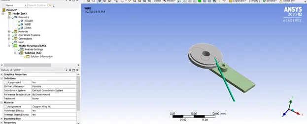
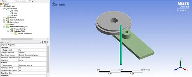
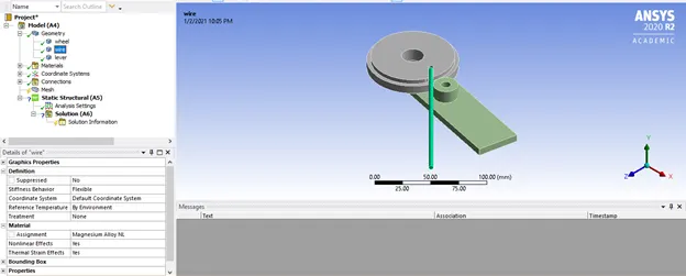
Rest both the component, lever and wheel being structural steel
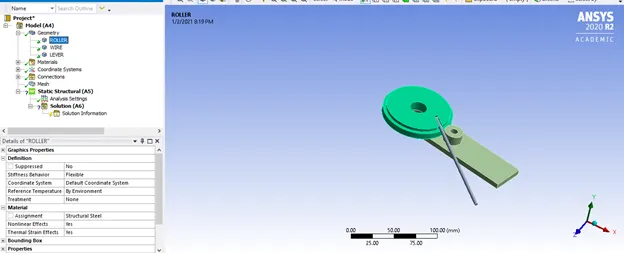
Post assignment of the materials to the components, go for contacts. Delete all the default contacts, and create/insert new contact. 2 contacts to be inserted, one between lever and wire and the other being wire and wheel.
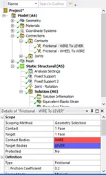
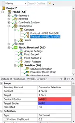
After the contacts, insert a joint with the below parameters,
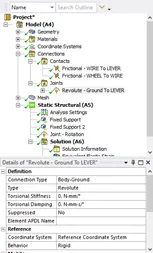
Now, Insert the mesh method for all the components,
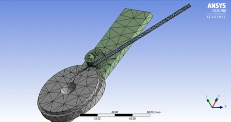
Select by solid selection of all the three components and assign the method of meshing as TETRAHEDRON,
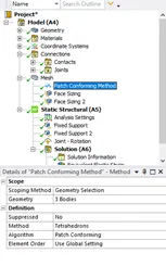
Insert sizing/face sizing 1 as the sizing of wire,lever area of contact & the area of the wheel which will come in contact with the wire at bend.
Now, create a coordinate system, with x-offset of 3 mm and z-offset of -3 mm. assign this coordinate system to the 2nd face sizing
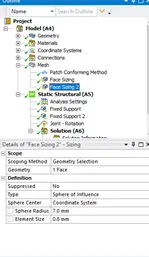
For Copper and Aluminium alloy:
Geometry = 1 face
Type = Sphere of influence
Sphere centre = Coordinate syste
Sphere radius = 8 mm
Element size = 0.75mm
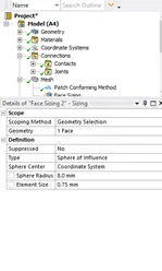
For magnesium alloy only :
Geometry = 1 face
Type = Sphere of influence
Sphere centre = Coordinate syste
Sphere radius = 7 mm
Element size = 0.8mm
Generating mesh
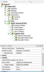
Also not to forgot to change the smoothening to low in quality parameters under mesh section.
After meshing go for Analysis Setting.
Number of steps=8
For step no.1
Auto time stepping = on
Define by = time
Initial time step = 0.1
Minimum time step = 1e-2
Maximum time step = 0.2
Solver type= direct
Weak springs = program controlled
Large deflection = ON
Change all the output controls to YES.
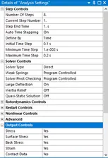
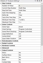
For step no 2-8:-
Auto time stepping=ON
Define by = time
Carry over step = ON
Minimum time step = 1e-2
Maximum time step = 1
Rest all the settings as given for step 1.
Insert fixed support at wheel and the wire.
Insert the Joint load at lever, and give tabular data of magnitude as:-
|
time |
Rotation angle |
|
0. |
0. |
|
1. |
-20. |
|
2. |
-40. |
|
3. |
-60. |
|
4. |
-80. |
|
5. |
-100. |
|
6. |
-120. |
|
7. |
-140. |
|
8. |
-140. |
Insert the solution requirements for Von-mises stress and Equivalent elastic strain for WIRE only. Recheck each and every parameters and values assigned and then solve for analysis.
Solution for each material is tabulated one by one below:-
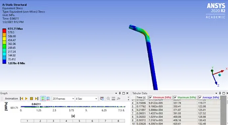
COPPER ALLOY:-
Von mises
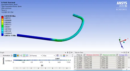
Equivalent elastic strain
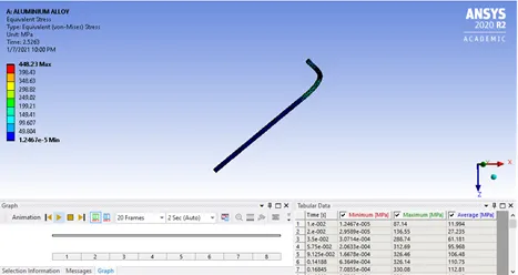
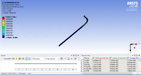
ALUMINIUM ALLOY:-
Von-Mises
Equivalent elastic strain:-
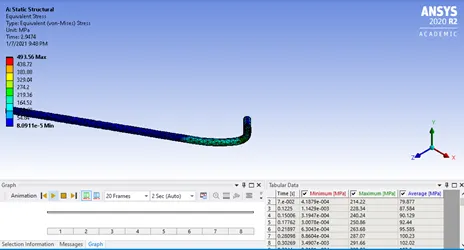
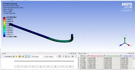
MAGNESIUM ALLOY:-
In magnesium alloy we have to change the face sizing for face 2 as 0.75
Von-mises:
Equivalent elastic strain:
CONCLUSION:-
The analyses and simulation has been run for 3 different material and the result for all the 3 are tabulated below:-
|
Material |
Von-mises stress(MPa) |
Equivalent elastic strain(mm/mm) |
|
Copper alloy |
651.71 |
0.0059783 |
|
Aluminium alloy |
448023 |
0.006373 |
|
Magnesium alloy |
493.56 |
0.011083 |
Below is the attached Google drive link for Workbench zipped folder for reference:
https://drive.google.com/file/d/1UtSpRz28OWzaaP3U4XMaf70ze08PS0xL/view?usp=sharing