Week 4 -Wire Bending Challenge
Objective:
The objective of this simulation is to study plastic defromation of bending wire. Three materials were chosen as wire material in order to study relative stress in each material. The analysis will compare wires of the following non-linear materials - Copper Alloy, Aluminium Alloy and Magnesium Alloy which are all non linear elements.
Analysis of Wire bending
Step 1: Geometry Creation
The geometry was imported from the model of bending assembly provided.
Step 2: Material Selection
There were a total of 4 materials considered for the sheet metal in this analysis as per the problem statement. The materials are, Alluminium, Magnesium and copper. These three materials are non-linaer materials taken from the general non-linear materials library.
Step 3: Meshing
3D meshing is done for the set up of wire bending. The mesh method was Tetrahedron and the mesh was automatic. The region of lever in contact with bending wire and the wire itself were meshed with a mesh size of 2.2 mm.
The section of the wheel which bends the wire and the rod in the bending region is meshed seprately with a fine mesh of 0.8 mm. For this purpose, the sphere of influnce method of mesh was done. A new co-ordinate system was created at the requisite location and used to define the sphere of influence of radius 7mm. The sections of rod and wheel in this sphere were meshed with a refined mesh.
Step 4: Processing
Processing the model involves creation of connections, Joints, Bouindary conditions, Loads etc.
1. Creation of Connections:
Contacts created by default were deleted except wire to lever contact. The same contact was duplicated to create a contact between the wire and wheel. A revolute joint was created to simulate the rotation of lever. Both contacts are frictional contacts with coefficient of friction 0.2 and augmented lagrange formulation and normal stiffness factor of 0.1. The stifneess has to be updated in each iteration whereas interface treatment set to 'Add offset, ramped effects'.
2. Analysis settings:
This solution is run in 8 steps considering the complexity of the analysis. We can observe the results in between the entire simulation at 8 individual points and study the changes in the sheet metal. Solver type is kept as 'direct' considering the complexity of the problem. The solution step 1 has different time step settings.
For step 1,
initial time step - 0.1 sec
min. time step - 1E-02 sec
max time step - 0.2 sec
For step 2-8,
Carryover time step - ON
min time step - 1E-02 sec
Max time step - 1 sec
3. Application of loads:
Since this simulation is performed to study the stresss in wire and wheel and lever, instead of applying loads, a rotation is applied on the lever. The lever is rotated by by 140 deg. in steps of 20 deg. each.
The wheel was fixed to facilitate seamless bending. The end of the rod was also fixed to prevent slipping of wire and unnecessary deformation.
Step 5: Results and Post-Processing
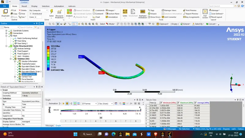
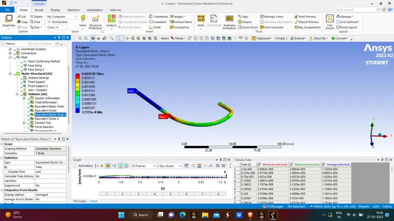
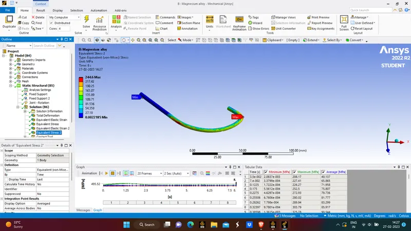
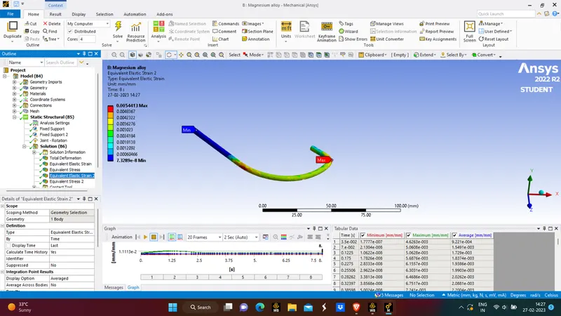
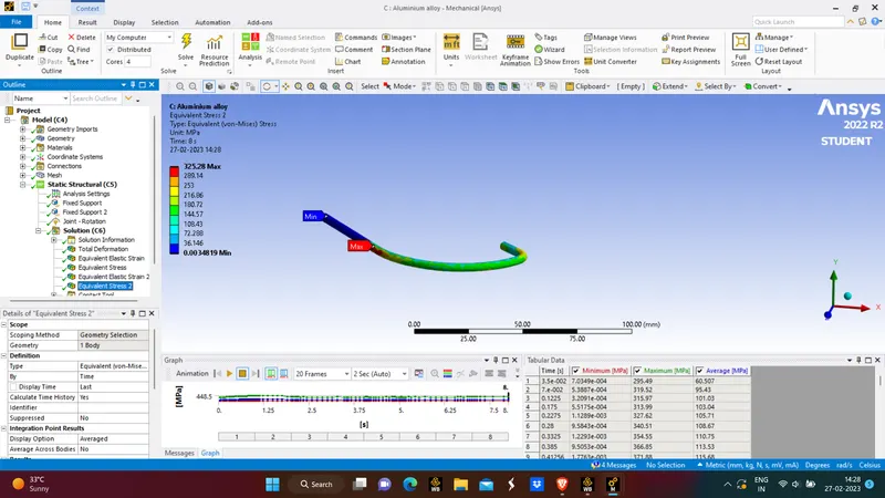
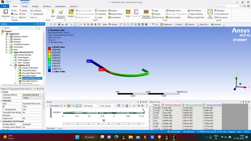
The objective of this simulation was to study the stress and strains on various materials viz., copper, aluminium and magnesium wire. The equivalent stress and strain contours are discussed here.
Copper
Magnesium
Aluminium
Conclusion
| Case(NL) | Equivalent Stress(MPa) | Equivalent Strain |
| Copper | 322.9 | 0.0029397 |
| Magnesium | 244.6 | 0.0054413 |
| Aluminium | 325.28 | 0.004622 |
- The stress in materials follow the same trend as that of youngs modulus i.e. stronger metal exhibits more stress.
- The strain contours follow reverse trend i.e. Stronger material exhibit smaller value of strain.
- The location of max stress and max strain is the same in all materials.
- Copper is the strongest material of all three choices.