Week 4 -Wire Bending Challenge
Aim :
To do analysis of wire bending in three different cases using ANSYS software.
Objective :
To perform analysis of wire bending in three different cases they are,
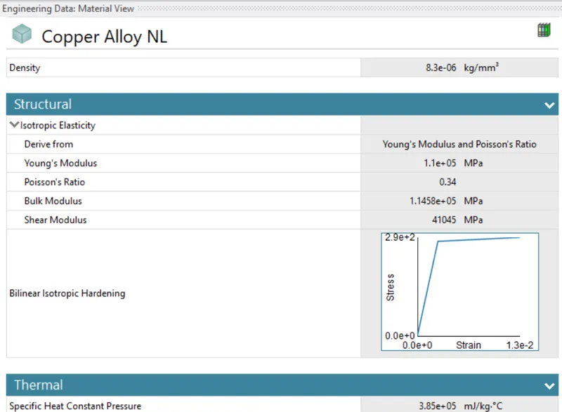
Case 1 : In this case with material property for wire as Copper alloy NL. We have to analyse and compare the solution values of different material property.
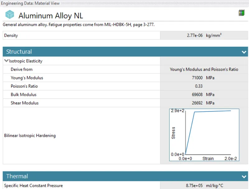
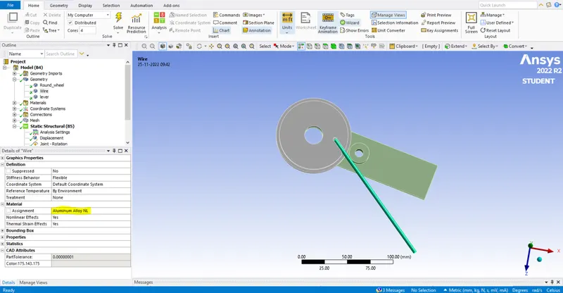
Case 2 : In this case with material property for wire as Aluminium alloy NL. We have to analyse and compare the solution values of different material property.
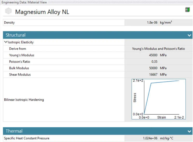
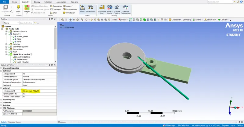
Case 3 : In this case with material property for wire as Magnesium alloy NL. We have to analyse and compare the solution values of different material property.
Given model :
Wire bending or wire forming is a technique used to shape metal into custom shapes used for manufacturing. Here in this challenge we bend the different material wire and compare the Equivalent stress and Equivalent strain values.
Procedure :
We start from workbench and choose static structural analysis.
In static structural we add material property which is required for the analysis.
We import the given model to the geometry tab.
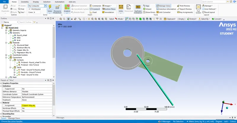
To work in the analysis we use mechanical graphical page and add the require data.
We assign the material property to the wire.
In connections part we define the contacts of the given model.
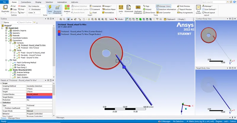
In this model we have two frictional contacts of frictional co-efficient 0.2.
The frictional contacts are between the wheel and wire and second contact between the wire and lever.
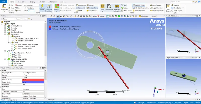
The behaviour is defined as program controlled and we us ethe formula as Augmented Lagrange.
We define the normal stiffness factor as 0.1, update stiffness for each iteration and interface as add offset, ramped effect.
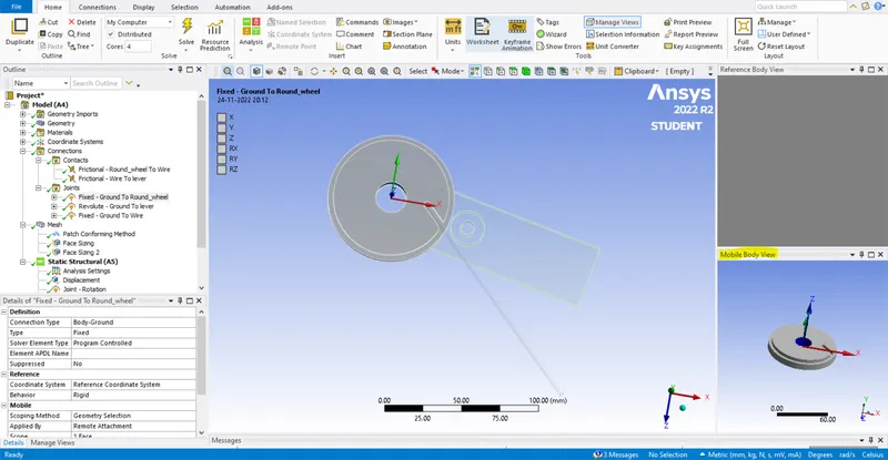
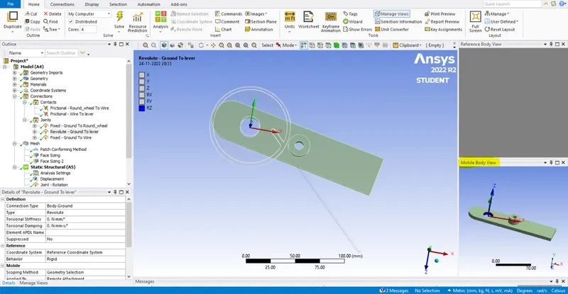
We define the joints as fixed body to ground for the wheel, revolute body to ground for the lever and fixed body to ground for the tip of the wire.
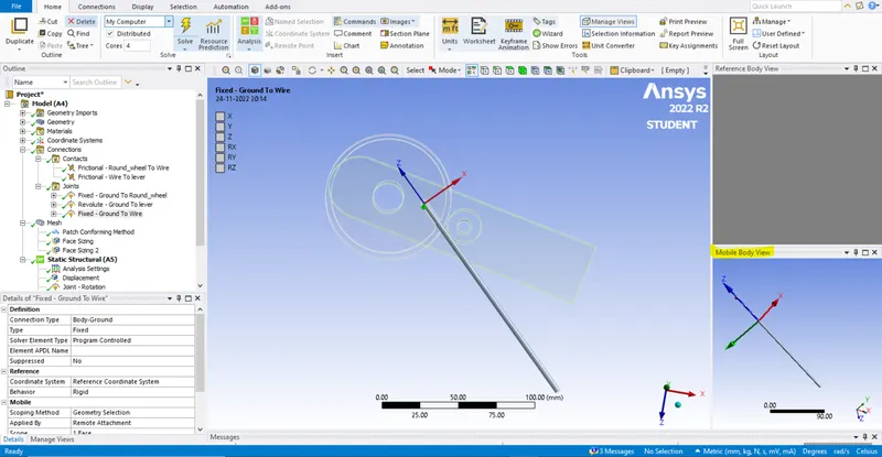
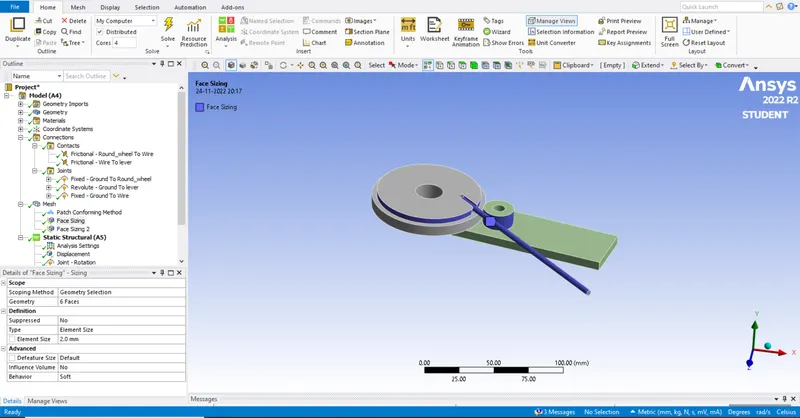
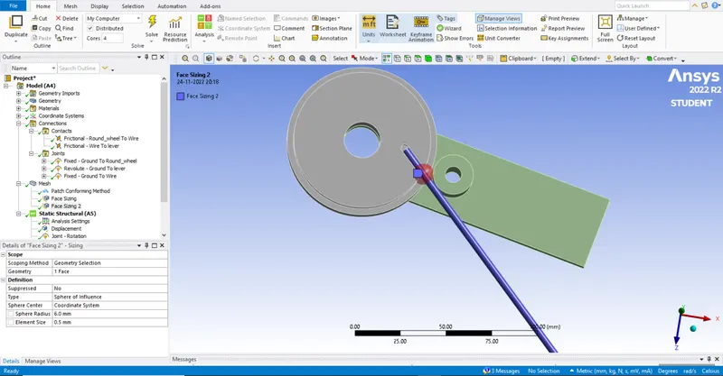
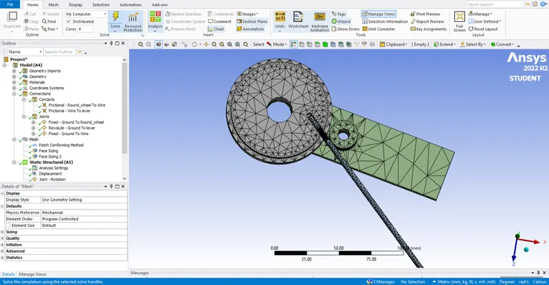
For meshing the contact areas are meshed for 2mm to attain accurate values and the rest areas are meshed for default values. With a help of new coordinate system we have created a sphere of 6mm to get accurate solution value we meshed the sphere area with 1.5mm mesh.
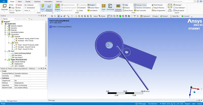
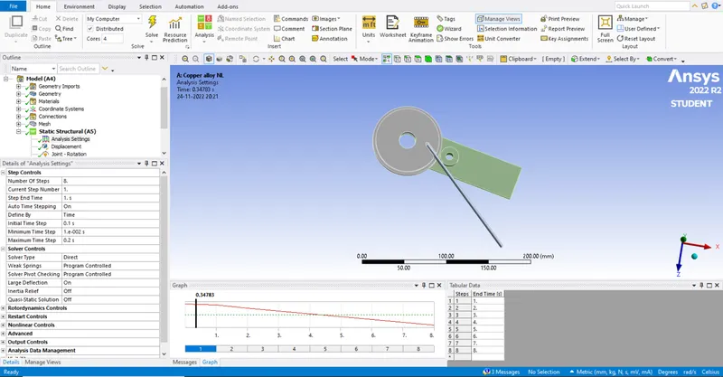
In analysis part we do the analysis for 8 steps with solver type as direct and large deflection ON.
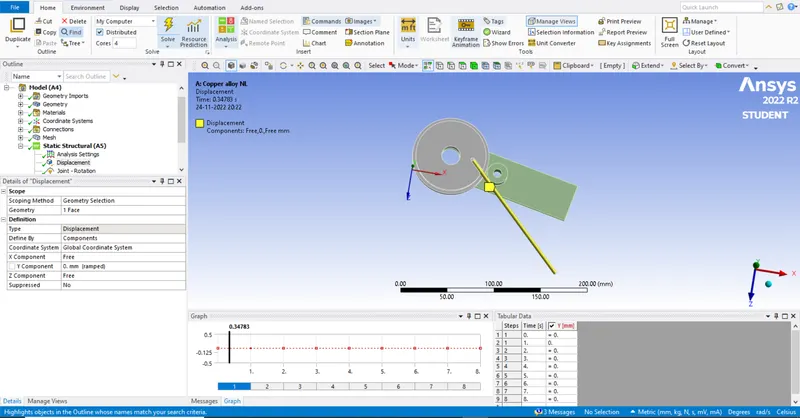
We define the tabular value for displacement of wire to be 0 (ramped) in Y component.
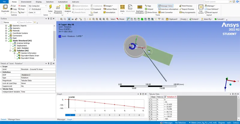
For rotational joint with DOF in Z direction the magnitude values are tabulated upto -160mm of lever rotation.
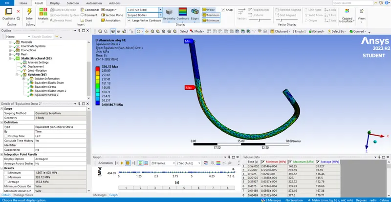
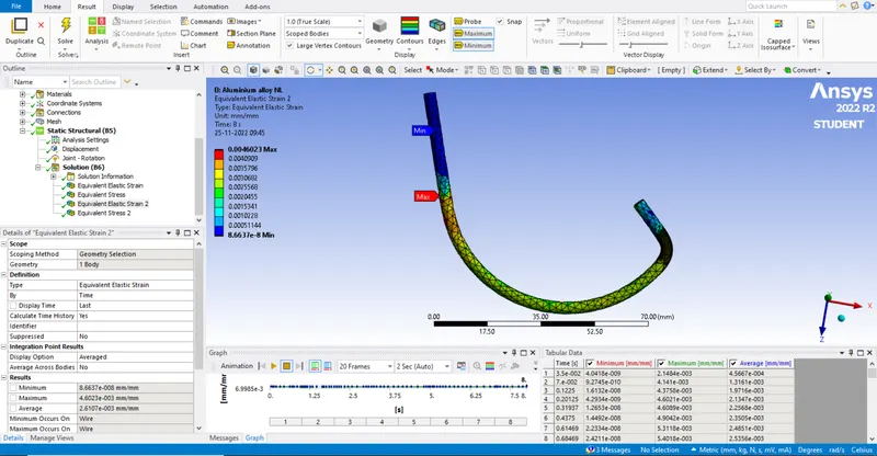
In solution it is asked to solve for Equivalent stress and Equivalent Elastic strain.
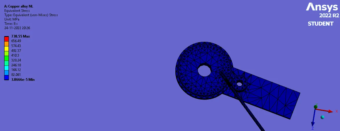
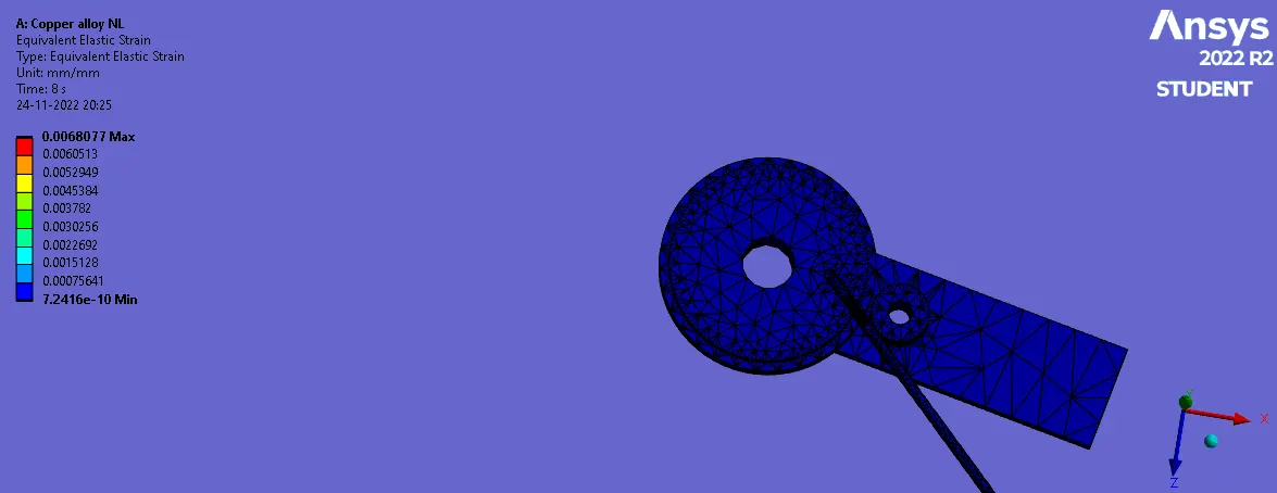
Conclusion :
It is asked to analysis and compare the solution of given model with three different cases. We ran the analysis to get the required solution and the results are tabulated below.
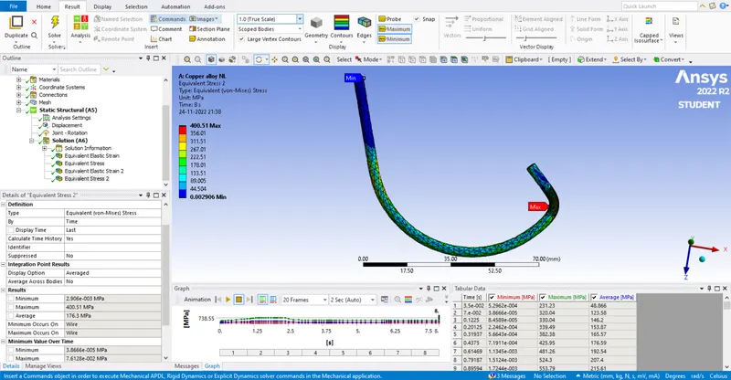
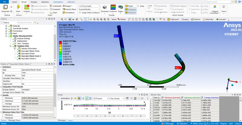
Case 1 : In this case with material property for wire as Copper alloy NL.
Case 2 : In this case with material property for wire as Aluminium alloy NL.
Case 3 : In this case with material property for wire as Magnesium alloy NL.
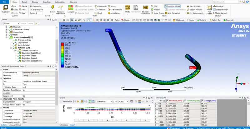
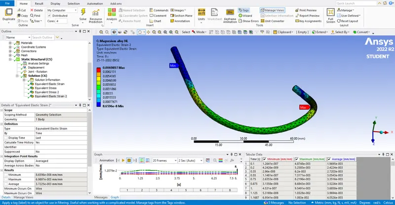
The change in values for stress and strain is tabulated below for comparision.
|
Sheet material /Required solution |
Equivalent stress |
Equivalent elastic strain |
|
Copper alloy NL |
400.51Mpa (max) 0.002906Mpa (min) |
0.0037125mm (max) 8.647e^-8mm (min) |
|
Aluminium alloy NL |
326.12Mpa (max) 0.0018671Mpa (min) |
0.0046023mm (max) 8.6637e^-8mm (min) |
|
Magnesium alloy NL |
312.17Mpa (max) 0.0011759Mpa (min) |
0.0069897mm (max) 8.6596e^-8mm (min) |
From the above table equivalent stress for Copper alloy NL has the maximum stress value.
Result :
The given model is analysed and the solution values of stress and strain are tabulated and compared successfully by using ANSYS software.