Week 4 -Wire Bending Challenge
WIRE BENDING CHALLENGE
Objective: -
We need to conduct an analysis to simulate the bending of a wire in ANSYS Workbench. We will assign 3 non-linear materials for the wire alone and determine the Equivalent stress and Equivalent strain on the wire alone.
Copper Alloy NL
Aluminium Alloy NL
Magnesium Alloy NL
CAD Model of the Lever, Wheel and Wire is incorporated for Analysis (Front view & Isometric view)
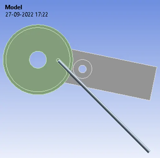
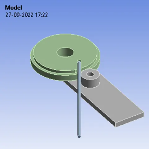
Material Properties have been taken from Engineering Data Sources of Ansys Workbench
|
Material Specifications for |
Density (Kgm^-3) |
Young’s Modulus [MPa] |
Bulk Modulus [MPa] |
Shear Modulus [MPa] |
Yield Strength [MPa] |
Tangent Modulus [MPa] |
|
Case I Aluminium Alloy |
2770 |
7.1E10 Pa or 71000 MPa |
6.9608E10 Pa or 69608 MPa |
2.6692E10 Pa or 26692 MPa |
2.8E8 Pa or 280 MPa |
5E8 Pa or 500 MPa |
|
Case II Copper Alloy |
8300 |
1.1E11 Pa or 110000 MPa |
1.1458E11 Pa or 114580 MPa |
4.1045E10 Pa or 41045 MPa |
2.8E8 Pa or 280 MPa |
1.15E9 Pa or 1150 MPa |
|
Case III Magnesium Alloy |
1800 |
4.5E10 Pa or 45000 MPa |
5E10 Pa or 50000 MPa |
1.6667E10 Pa or 16667 MPa |
1.93E8 Pa or 193 MPa |
9.2E8 Pa or 920 MPa |
Case I: Aluminium Alloy NL
Wheel and Lever material, it is Structural Steel and Wire material it is Aluminium Alloy NL
Connections
Contact Settings:
Initiating contact settings is crucial for the designer and end-user since the setting of contact surfaces is discretionary of the designer as to what to ignore and which to consider. Here the Wheel, Lever and Wire are in constant contact to undergo dynamic attributes of stresses, strains and deformations as such the designer have to closely observe and predict the cognitive analytical ability to consider it as crucial for setting the contact region and ignoring other factors for efficient (i.e. Saving Time and Energy) Way of Analysing.
Contacts allowing separation (e.g. frictional contacts) are non-linear contacts. For FE models with non-linear contacts, an iterative process is involved to obtain a solution and therefore non-linear contact analyses are more computationally demanding.
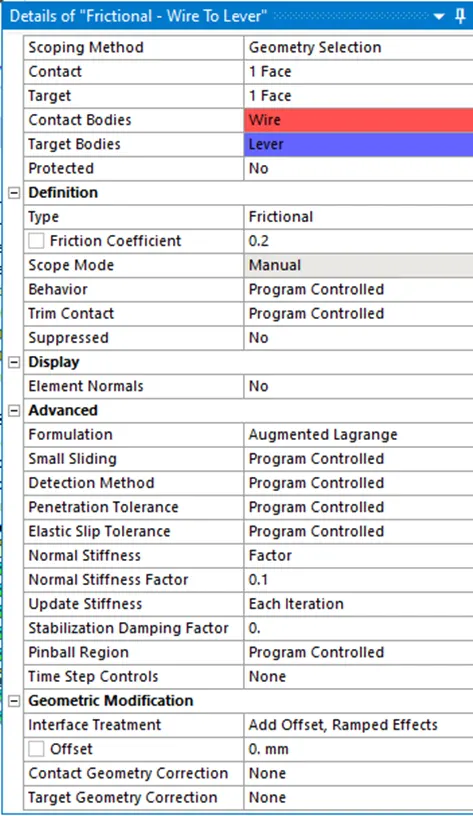
Frictional – Wire to Lever
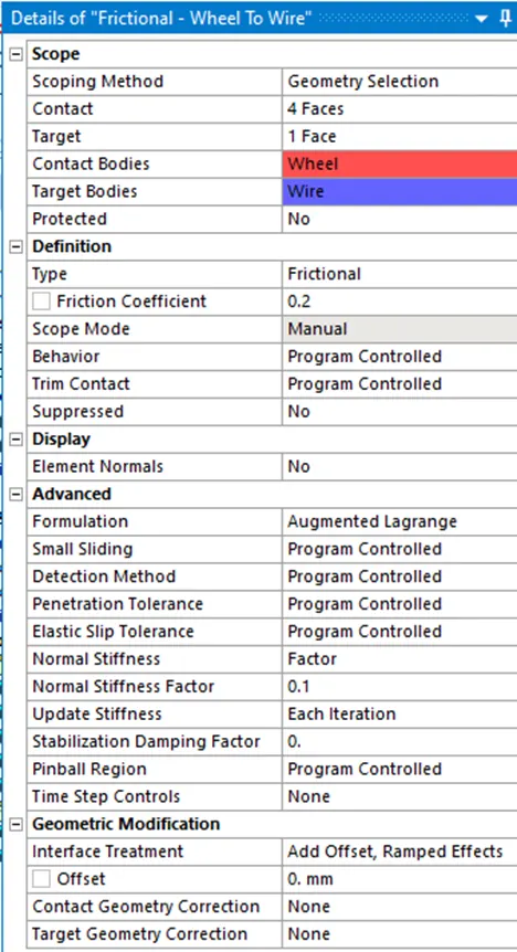
This state is known as “sticking.” The model defines equivalent shear stress (shear stress refers to cases where the deforming force is parallel to a surface) at which sliding on the geometry begins as a fraction of the contact pressure. Once the shear stress is exceeded, the two geometries will slide relative to each other. The coefficient of friction can be any nonnegative value, here we take it as 0.2, Similar parameters are followed for copper alloy NL and Magnesium alloy NL.
shear stress, the force tending to cause deformation of a material by slippage along a plane or planes parallel to the imposed stress.
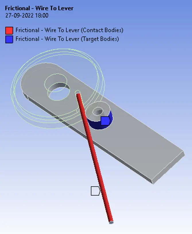
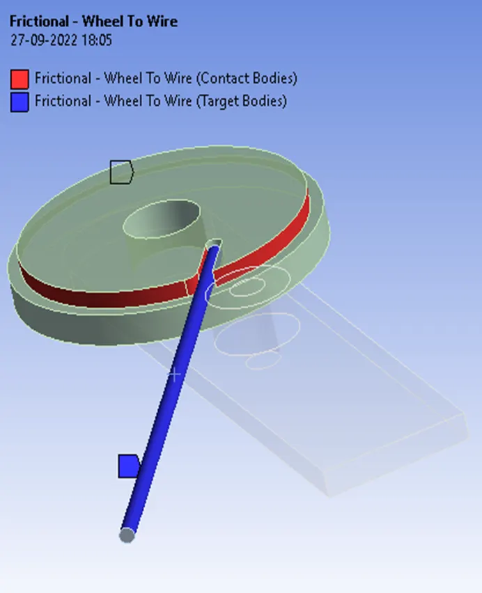
Frictional Wheel to Wire
Joints
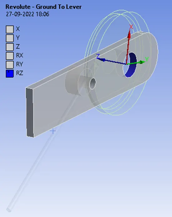
Revolute Joint
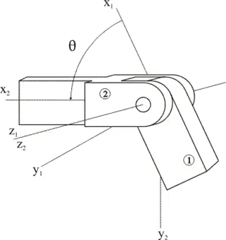
A revolute joint, sometimes called a pin or hinge, is shown in the diagram below with the two bodies and body-fixed reference frames that it connects. A revolute joint allows a single relative rotation of the two frames; this joint type prevents all of the other relative rotations and translations.
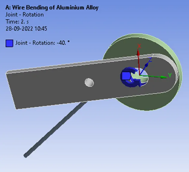
In our analysis, the revolute joint is given to the Lever.
Meshing Details
For the meshing part of default solver settings, the ANSYS solver will use the default or recommended mesh value for the model.
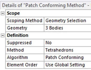
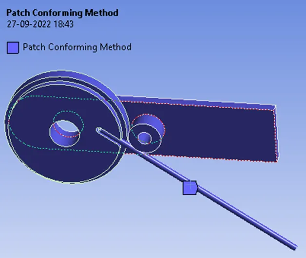
Patch Conforming Method
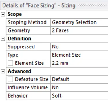
Face sizing
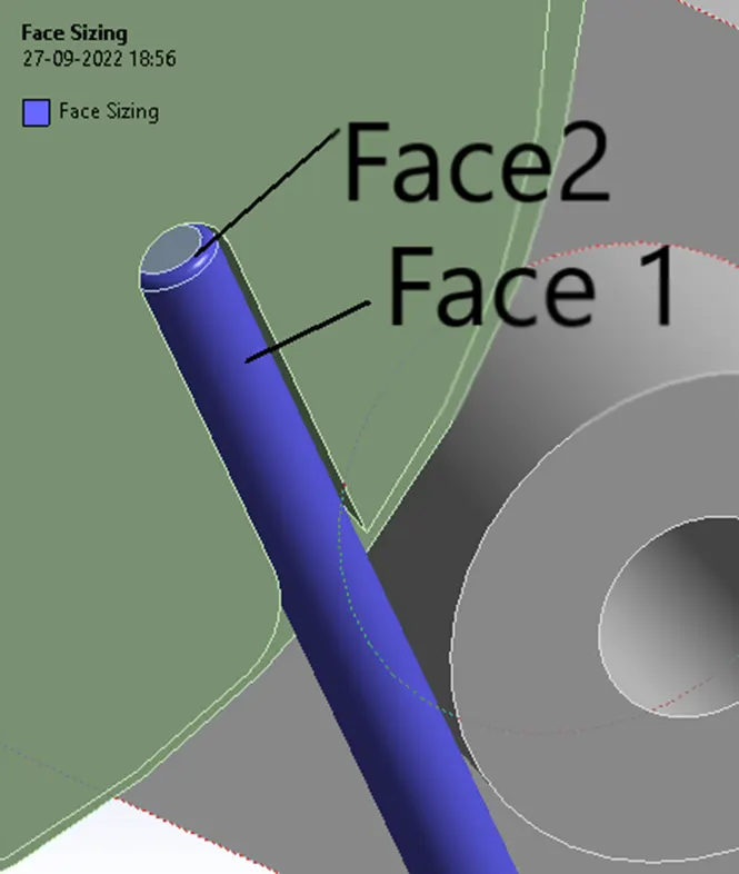
Face Sizing 2
Before selecting any faces go to  and expand it and click Coordinate system
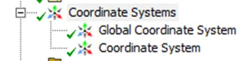
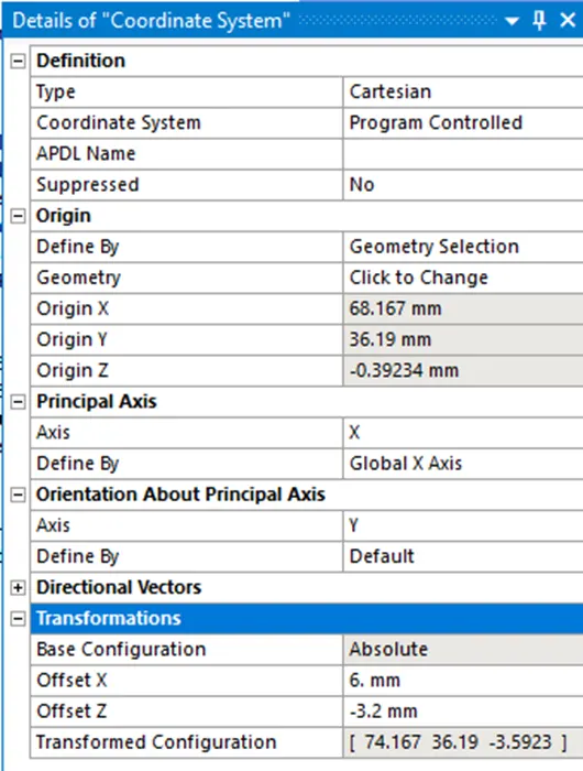
In Transformations, Select X offset and Z offset and enter values as 6mm and -3.2mm so that our new coordinate system is created on the wire for that particular area when using the sphere of influence in meshing. Now you can see the new coordinate system is created on the wire.
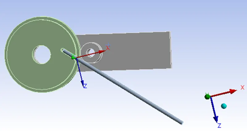
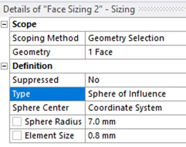
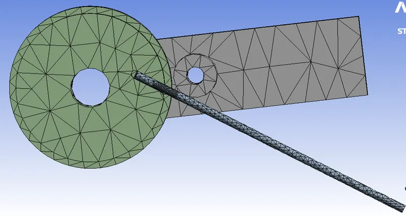
Now got to Mesh Right-Click select sizing Select the Face of the wire only and in the Type choose Sphere of influence and in the Sphere centre select the new coordinate system you created in Transformations, and give Sphere radius as 7mm and Element size as 0.8mm

Further on Applying all parameters to meshing and selecting Generate Mesh the updated mesh is represented below
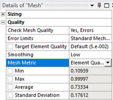
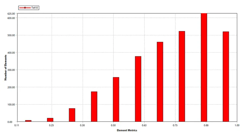
Mesh Metric:
Element Quality
The Element quality option provides a composite quality metric that ranges between 0 and 1 and this metric is based on the ratio of the volume (or area) to the square of the edge length.
So a Value of 1 indicates a perfect cube or square or triangle or hexagon or quad while a Value of 0 indicates that the element has a zero or negative volume
Boundary Conditions
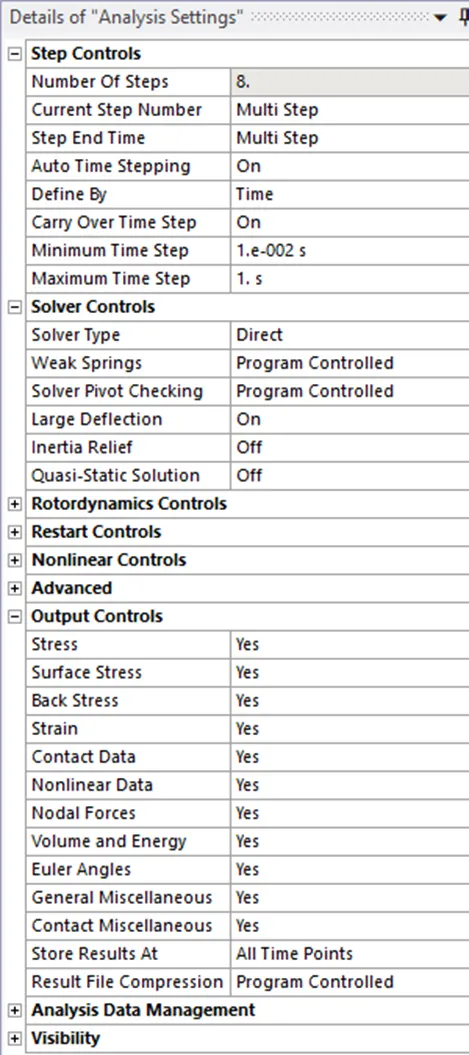
Analysis settings:
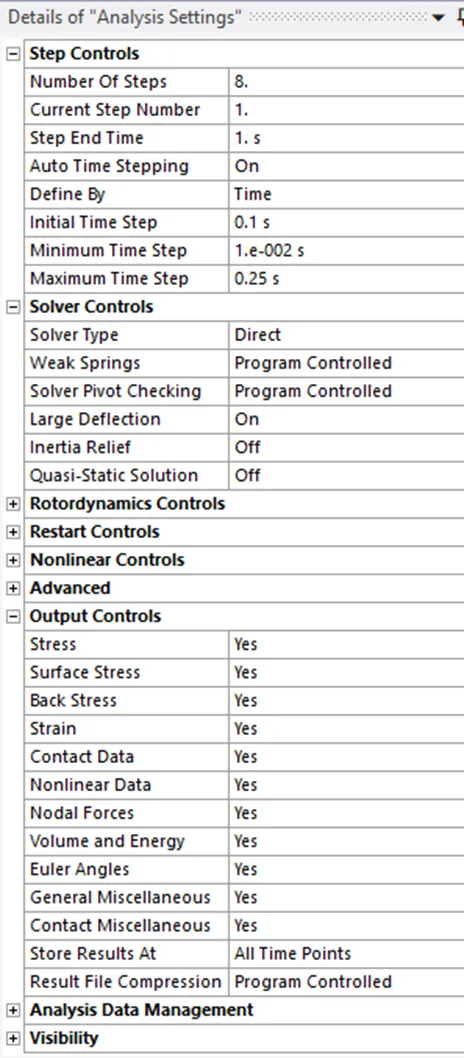
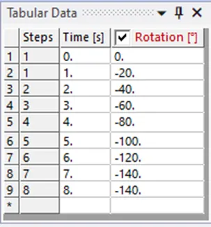
The Time Step controls of Analysis settings are crucial for Convergence of Force and Criterion values /curves as this helps the solver converge without any issues.
If we take a smaller time step the solver finds it easy to start with the initial calculation and slowly increases to its maximum time step which helps the solver converge faster without any issues. So always keep this in mind in case you are experiencing any convergence issues try to reduce the time step values and start with a less value so that it helps the solver converge faster. A similar procedure is observed for the other two cases
Analysis Settings for Ist Step and Analysis Settings for steps 2 to 8
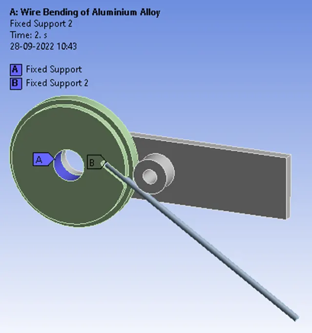
Fixed Support for Wheel and Wire
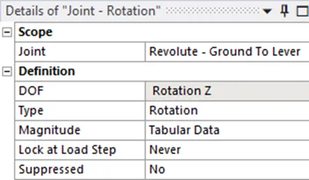
Joint Rotation to Lever
Simulation Results
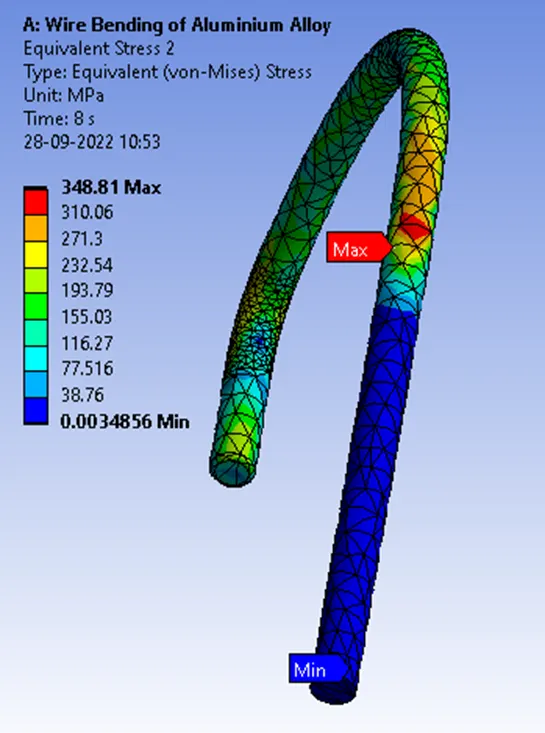
Case I Wire Material of Aluminium Alloy NL
Equivalent Stress on Wire
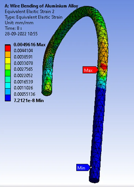
Equivalent Elastic Strain on Wire
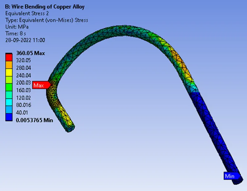
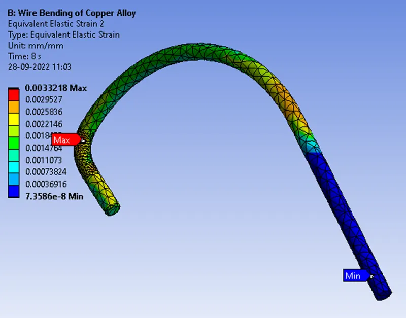
Case II Wire Material of Copper Alloy NL
Equivalent Stress on Wire
Equivalent Elastic Strain on Wire
Case III Wire Material of Magnesium Alloy NL
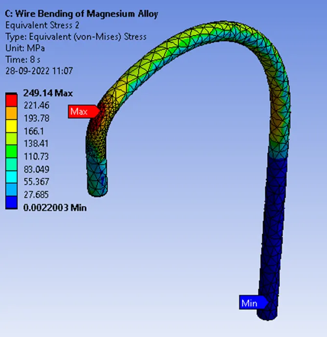
Equivalent Stress on Wire
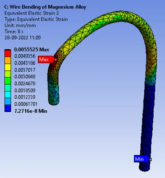
Equivalent Elastic Strain on Wire
Concluding Result
What is Rigidity? It is the ability of a material to not bend when a force is applied.
What is shear modulus?
Shear modulus, also known as Modulus of rigidity, is the measure of the rigidity of the body, given by the ratio of shear stress to shear strain. Rigidity is a material’s resistance to bending, whereas strength is a material’s resistance to breakage. Rigidity is the property of a structure that it does not bend or flex under an applied force. The opposite of rigidity is flexibility.
A large shear modulus value indicates a solid is highly rigid. In other words, a large force is required to produce deformation.
A small shear modulus value indicates a solid is soft or flexible. Little force is needed to deform it.
Since our Analysis is about the wire bending let us compare our stress and strain results with the shear modulus or Modulus of rigidity as to whether to determine which one of the non-linear materials will bend larger or it is Rigid.
|
Analysing Cases for |
Equivalent Stress on Wire [MPa] |
Equivalent Elastic Strain on wire [MPa] |
Shear Modulus [MPa] |
Young’s Modulus [MPa] |
|
Case I Aluminium Alloy NL |
348.81 |
0.0049616 MPa or 4.9616E-9 Pa |
2.6692E10 Pa or 26692 MPa |
7.1E10 Pa or 71000 MPa |
|
Case II Copper Alloy NL |
360.05 |
0.0033218 MPa or 3.3218E-9 Pa |
4.1045E10 Pa or 41045 MPa |
1.1E11 Pa or 110000 MPa |
|
Case III Magnesium Alloy NL |
249.14 |
0.0055526 MPa or 5.5525E-9 Pa |
1.6667E10 Pa or 16667 MPa |
4.5E10 Pa or 45000 MPa |
From our results, we observe that compared to Aluminium and Magnesium alloy non-materials, Copper alloy non-material has less stain at 3.3218E-9 Pa which clearly shows that it is highly rigid where a large force is required to produce deformation.
Finally, we can conclude that out of 3 non-linear materials one of them has high rigidity or a material's resistance to bending is tabulated from the Descending order (Top to Bottom).
|
Material |
Rigidity Rating |
|
Copper Alloy NL |
Highest |
|
Aluminium Alloy NL |
Medium |
|
Magnesium Alloy NL |
Low |