Week 4 -Wire Bending Challenge
OBJECTIVE To perform an analysis to simulate the bending of a wire by assigning different materials to the wire and analyze the Equivalent stress and Equivalent strain acting on the wire in each case.
CASE 1 Copper Alloy
CASE 2 Aluminum Alloy
CASE 3 Magnesium Alloy
PRODECURE
Create Static Structural Analysis and in engineering data select the material structural steel for other components of geometry and Copper Alloy , Aluminium Alloy and Magnesium Alloy for wire in diffrent cases
STRUCTURAL STEEL
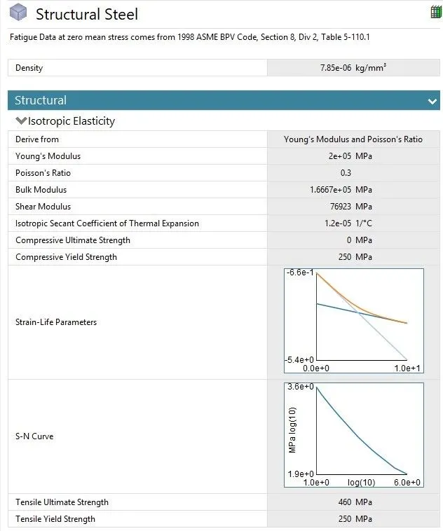
CASE 1 COPPER ALLOY CASE 2 ALUMINIUM ALLOY CASE 3 MAGENISUM ALLOY
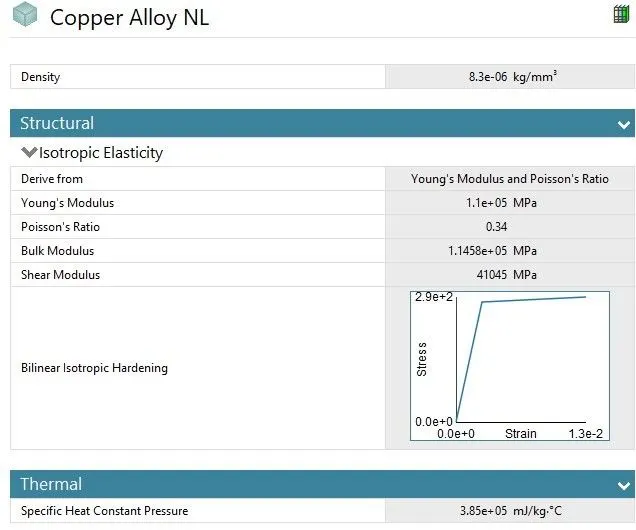
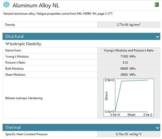
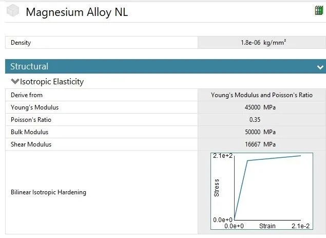
Import the geometry and check in Spaceclaim for any irregularties.
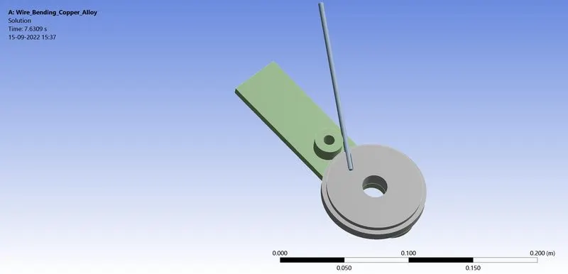
Then open Ansys Mechanical and rename the geometry as wheel , lever and wire then assign the structural steel material to wheel and lever and copper alloy , Aluminium alloy and Magnesium Alloy for wire in different cases.
CONTACTS
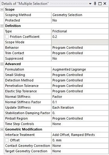
Two contacts created in the whole setup with frictional type with friction coefficient of 0.2 formulation set to augmented Lagrange , Normal stiffness to factor and value for the factor set to 0.1 , update stiffness for each iteration and interface treatment is set to add offset Ramped effects.
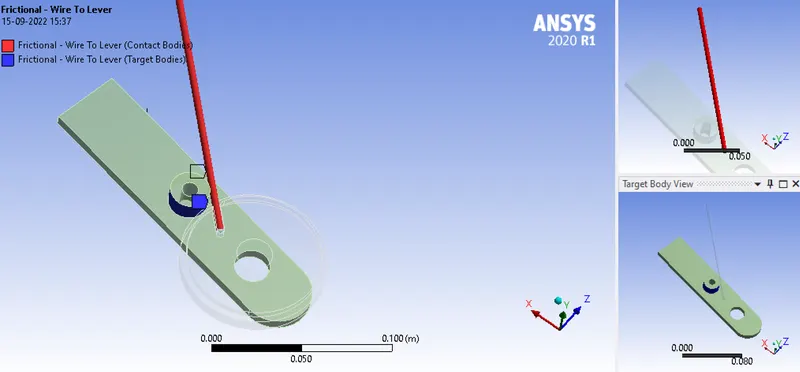
CONTACTS FRICTIONAL WIRE TO LEVER
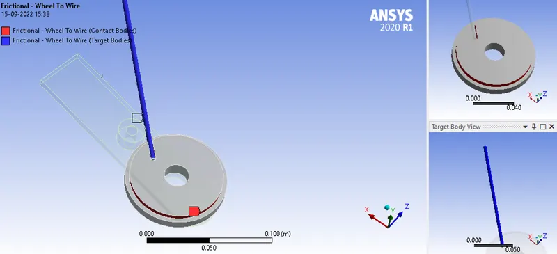
CONTACT FRICTIONAL WHEEL TO WIRE
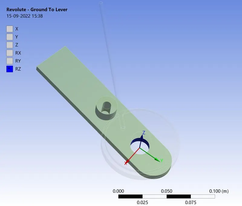
REVOLUTE JOINT
Is created for the lever it is ground to lever revolute joint.
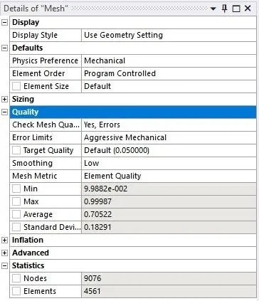
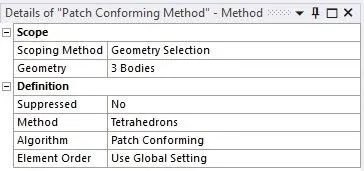
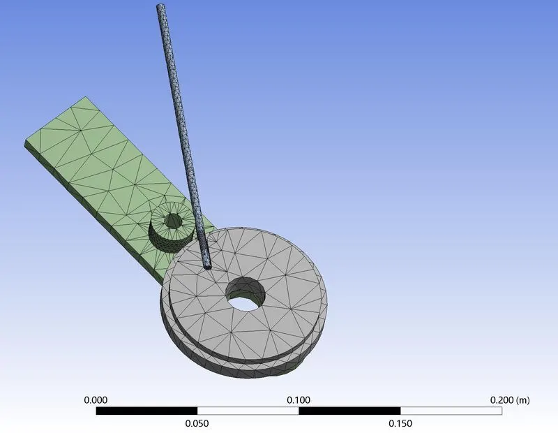
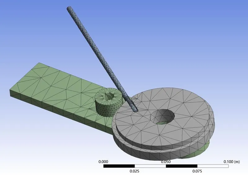
MESH In mesh the whole geometry first we use the method patch conforming method and method set to tetrahedrons
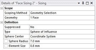
MESH FACE SIZING A coordinate system is defined at the filleted surface of the wheel with an offset of 3mm and 3mm in the X and Z directions respectively . A face size of 0.8mm is defined for the regions lying ina 7mm radius around the sphere center of this coordinate system.
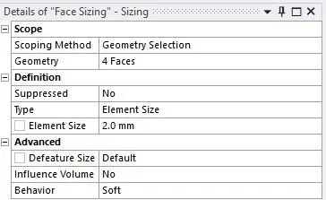
The rest of the assemebly mesh with the default mesh.
ANALYSIS SETTINGS
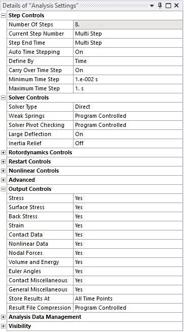
The simulation runs for 8 steps so that number of steps is set as 8 . The first step solver type is direct large deflection set to on and defined by time .Intial time step set to 0.1s Minimum time step set to 1e-2s and maximum time step to 0.2s .In output control set all output to ues.
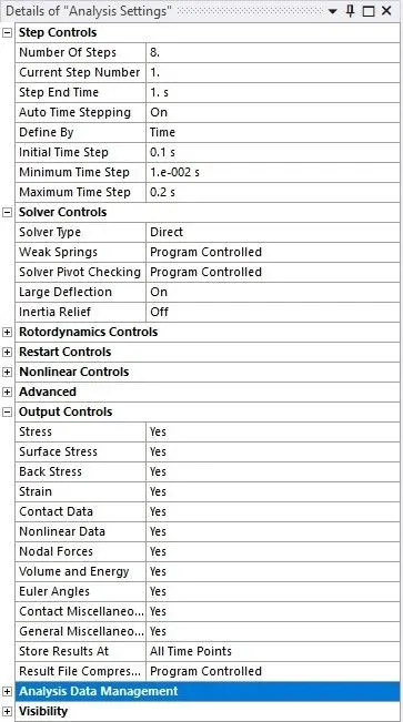
The second step to eight step solver type is direct , large deflection set to on and defined by time .Carry over time set to on Minimum time step set to 1e-2s and maximum time step set to 1s .Im output control set all output to yes.
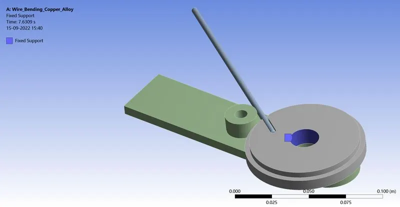
FIXED SUPPORT
The wheel provides fixed support to constrain the movement of the wheel
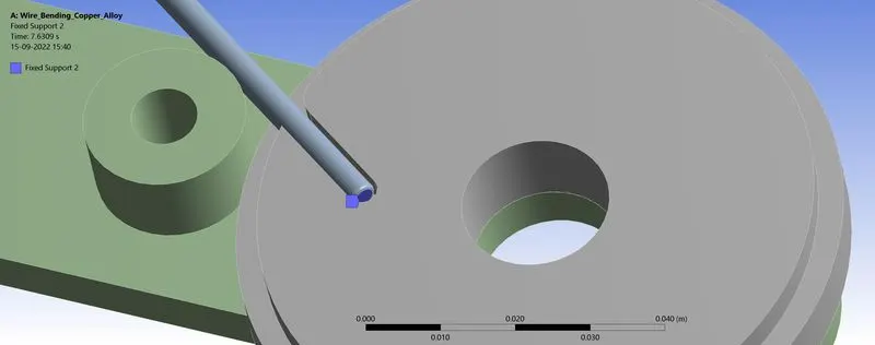
FIXED SUPPORT
The wire face provides fixed support to stop it moving out from the wheel.
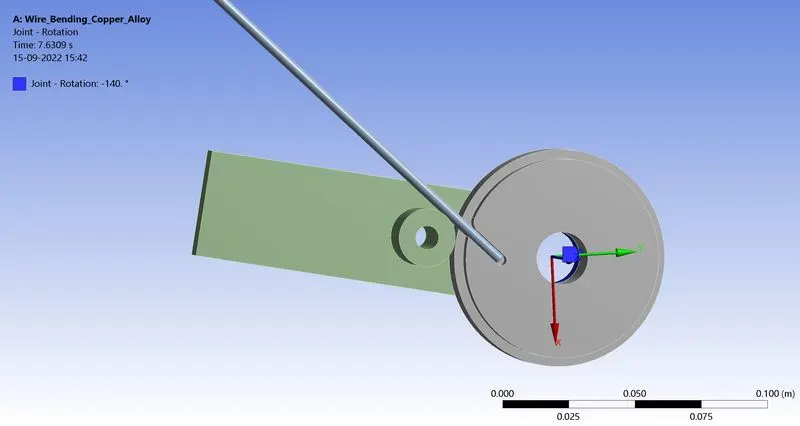
JOINT ROTATION
Lever is provided with a rotation of 140 degree.

Run the simulation and result obtained.
RESULT The analysis runs successfully and results obtained.
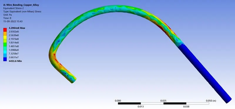
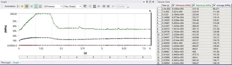
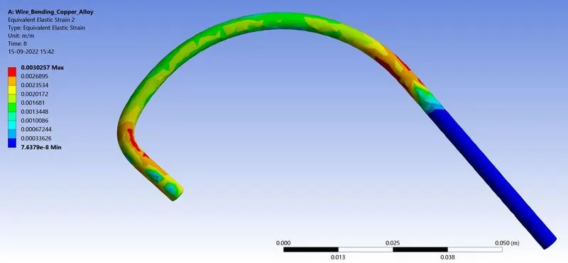
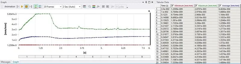
CASE 1 COPPER ALLOY
Equivalent Stress Max - 329.64 Mpa
Equivalent Strain Max - 0.0030257 mm/mm
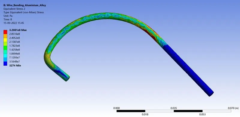
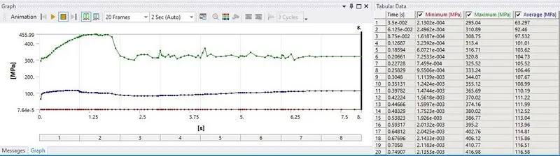
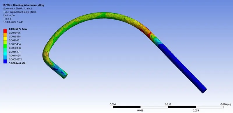
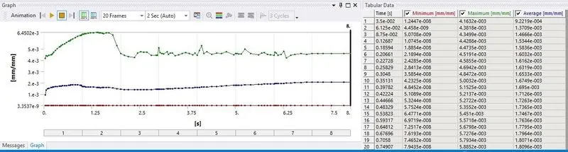
CASE 2 ALUMINIUM ALLOY
Equivalent stress max - 320.81 Mpa
Equivalent Strain Max - 0.0045872 mm/mm
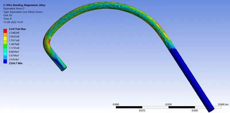
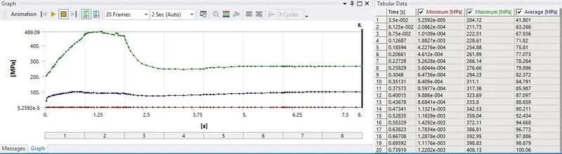
CASE 3 MAGNESIUM ALLOY
Equivalent Stress Max - 264.17 Mpa
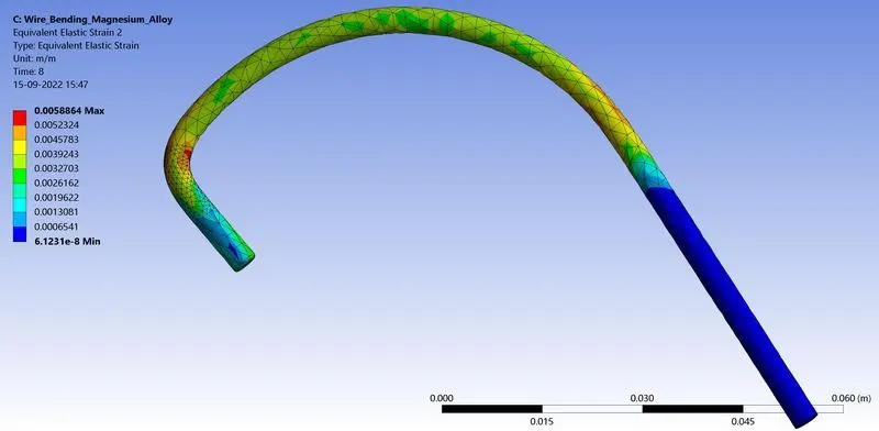
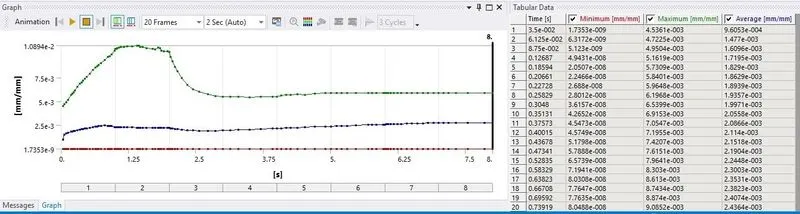
Equivalent Strain Max - 0.0058864 mm/mm
CONCLUSION
|
MATERIAL |
EQUIVALENT STRESS MAX Mpa |
EQUIVALENT STRAIN MAX mm/mm |
|
COPPER ALLOY |
329.64 |
0.0030257 |
|
ALUMINIUM ALLOY |
320.81 |
0.0045872 |
|
MAGNESIUM ALLOY |
264.17 |
0.0058864 |
- The equivalent stress is maximum for Copper Alloy wire and minimum for Magnesium Alloy wire
- The equivalent strain is maximum in Magnesium alloy and minimum in copper alloy wire.
LINK : https://drive.google.com/file/d/1lgneohVmKx4RxQ1aOWLOoRPt26FlXeqj/view?usp=sharing