Week 4 -Wire Bending Challenge
AIM:
To simulate the wire bending for their total deformation,stress and strain using ansys workbench.
WIRE FORMING:
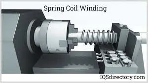
Wire forming is the process of taking wire, either from a spooled coil or blank length, and bending it into specific forms. Wire forms are extremely flexible, allowing them to be modified into a wide variety of shapes and specific configurations. Wire forming is a method for applying force to change the contour of wire by bending, swaging, piercing, chamfering, shearing, or other techniques. The various techniques for wire forming can produce any type of shape, form, or configuration. The process starts with coiled wire that is straightened before being formed.
CNC wire forming or wire bending is an advanced technique used to manipulate metal into standard or customized shapes for the manufacturing of products. Consisting of various shapes and sizes, wire forms are fabricated with machines through heat treatment, cutting and bending. CNC wire bending involves bending and cutting wire to form. Our skilled team members and reliable machines can ensure your wire forms are cut with absolute precision. CNC stands for “Computer Numerical Control”. CNC wire bending uses newer equipment than other types of precision wire form
PROCEDURES:
- Drop the static structural from the analysis settings.
- Allocate the required material from the engineering data.
- Then import the geometry, next update, then open the model
Materials:
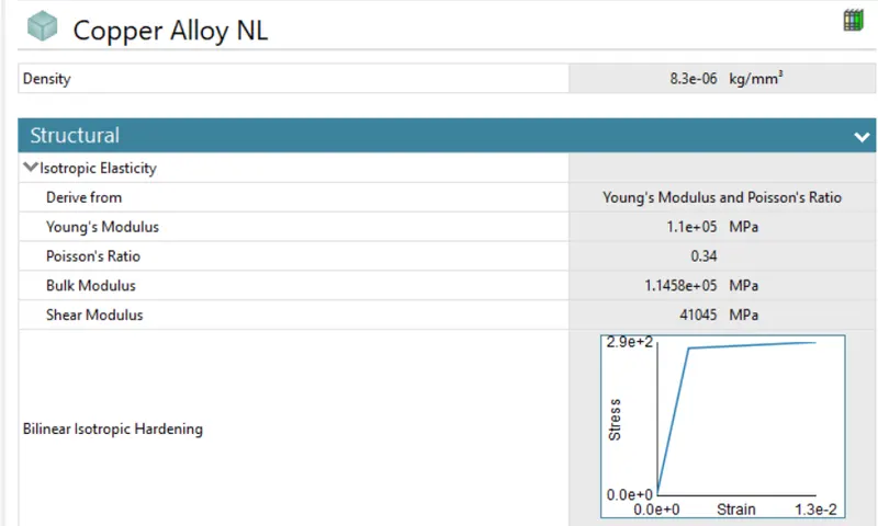
Copper Alloy
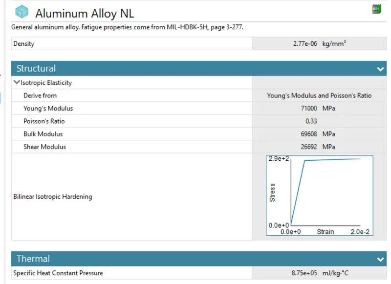
Aluminium Alloy
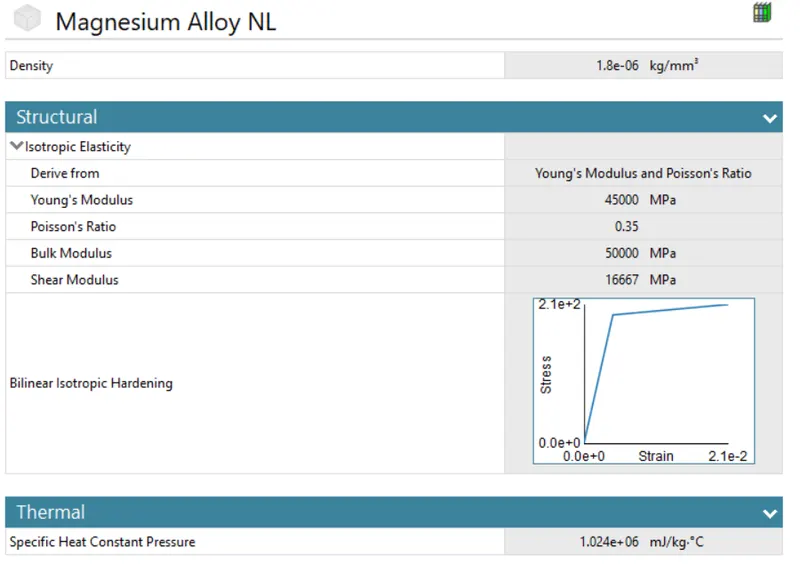
Magnesium Alloy
Geometry:
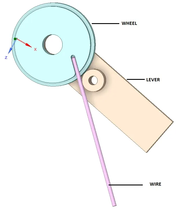
- First change the default name to WHEEL,WIRE,LEVER.
- Assign the selected material WIRE - (copper alloy,Aluminium alloy,Megnesium alloy), WHEL and LEVER - structural steel.
Connections
- In the default contact,delete first two contact, then duplicate the contact 3, right click and choose the Flip Contact/target, again right click choose Rename based on definition.
- In the contact wire - wheel increase the target then apply.
- Now select the both contact
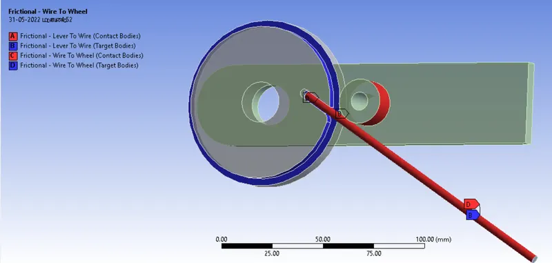
Type = frictional
Frictioal coefficent = 0.2
Normal stiffness = Factor
Normal stiffness factor = 0.1
Update stiffness = Each iteration
interface treatment = Add offset Rambed effects
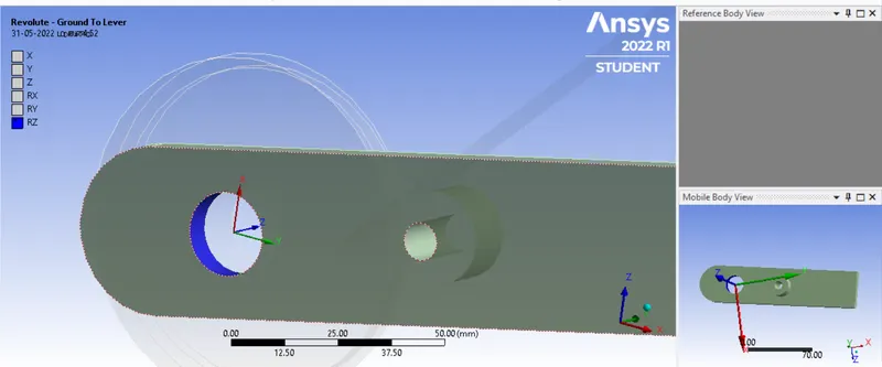
- Insert the revolute joint for ground to lever, select the inside circule of the lever, then apply.
Mesh:
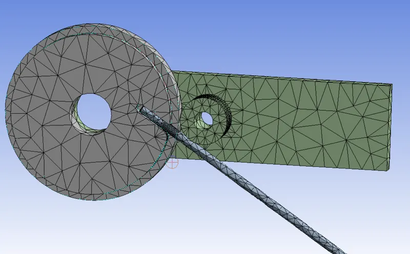
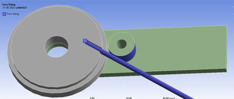
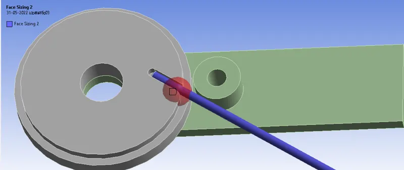
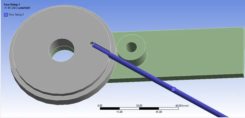
- Now mesh, insert method, select the WHEEL,WIRE,LEVER apply, change the tetrahedrons as method.
- insert the sizing, select the contact with wire and apply.Element size is 2mm
- Then create new coortinate for the between wire and wheel, select the x and z offset. x offset= 3mm and z offset = -3mm
- Insert the sizing select the wire, type = sphere of influnce, sphere center = coordinate system,spaceradius =7mm element size = 0.8mm
Boundary conditions:
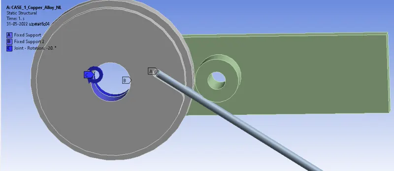
No of step = 8
STEP = 1
Slover type = Direct
Large deflection = ON
Auto time steeping = ON
Defined by = Time
Initial time = 0.1
Minimum time = 1e-2
Maximum time = 0.2
output controls = ALL "YES"
STEP = 2-8
Slover type = Direct
Large deflection = ON
Auto time steeping = ON
Defined by = Time
Carry over time = ON
Minimum time = 1e-2
Maximum time = 1
output controls = ALL "YES"
- Insert fixed support, select the wire edge and apply.
- Again insert the fixed support ,select the inside circule of the wheel then apply.
- Now insert the revolute joint select the inside circule of the lever, revolute ground to lever, type = rotation
Soluitions:
- After giving proper boundary conditions,create desired solutions for output results,create solutions for Directional deformation, stress and strain. slove evaluate for solutions.
RESULTS:
case= 1
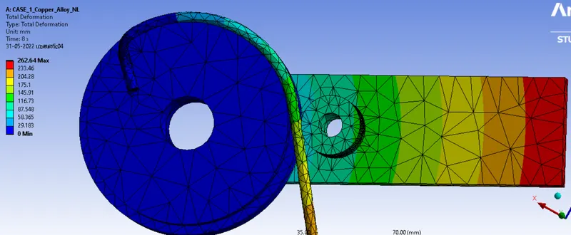
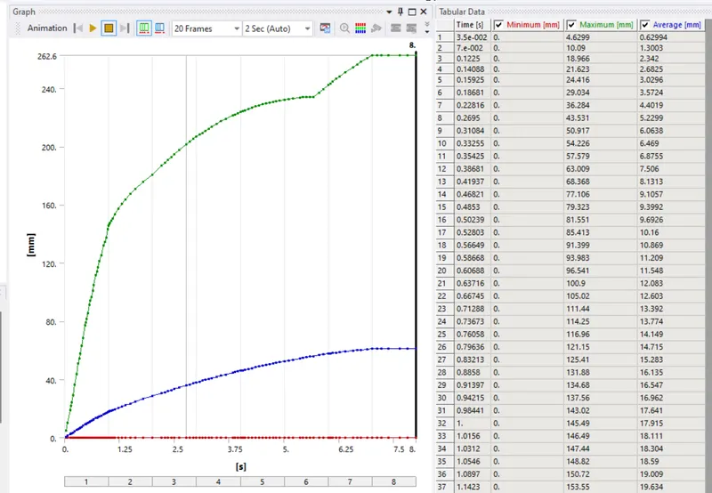
Total Deformation And Graph
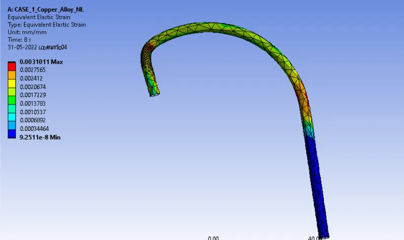
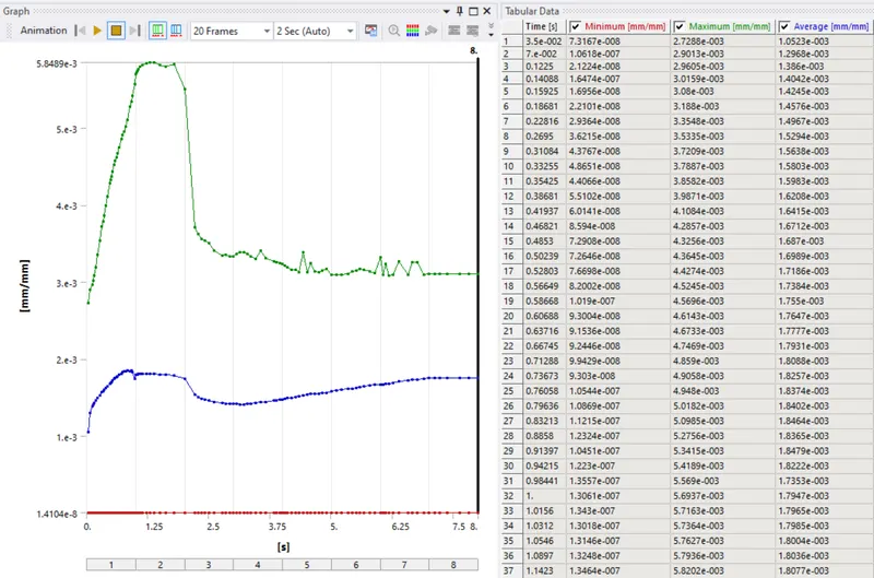
Equivalent Elastic Strain And Graph
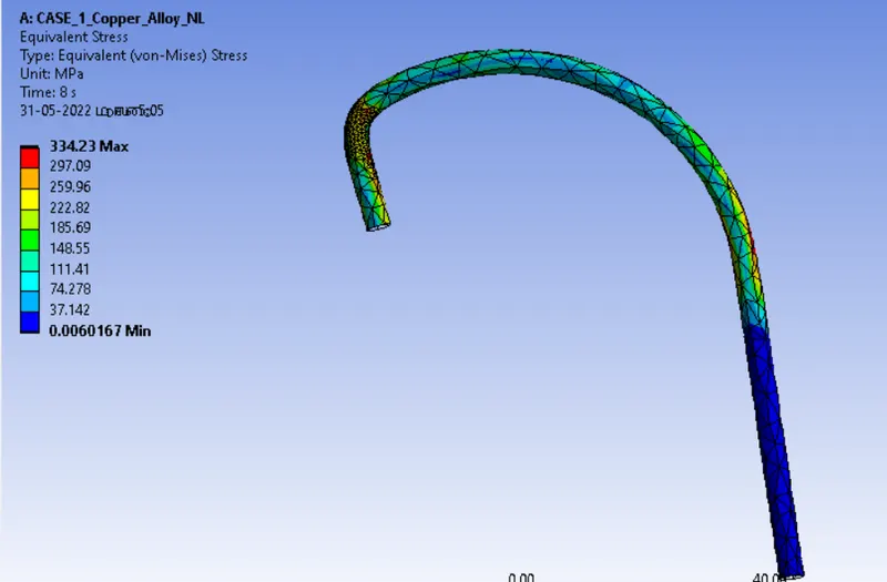
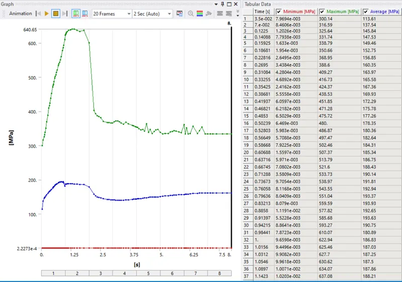
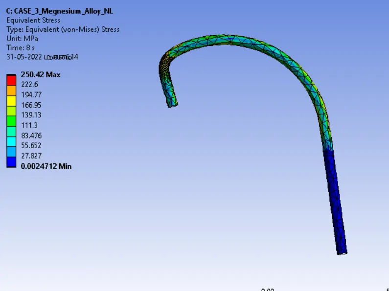
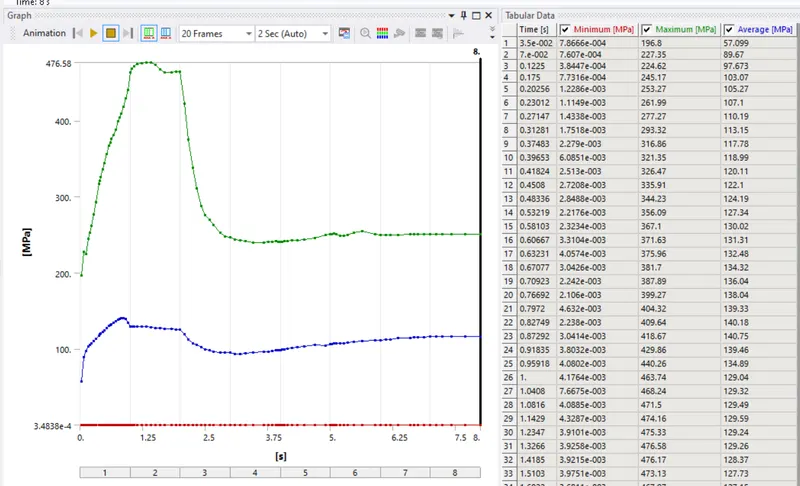
Equivalent Stress And Graph
case= 2
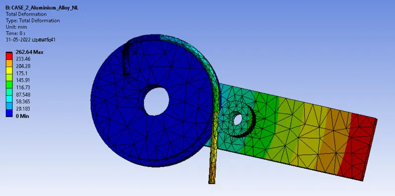
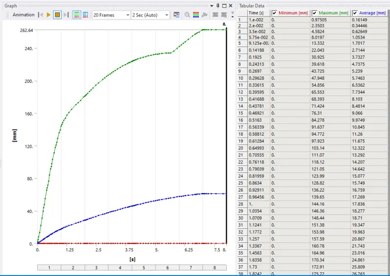
Total Deformation And Graph
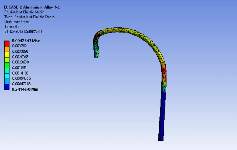
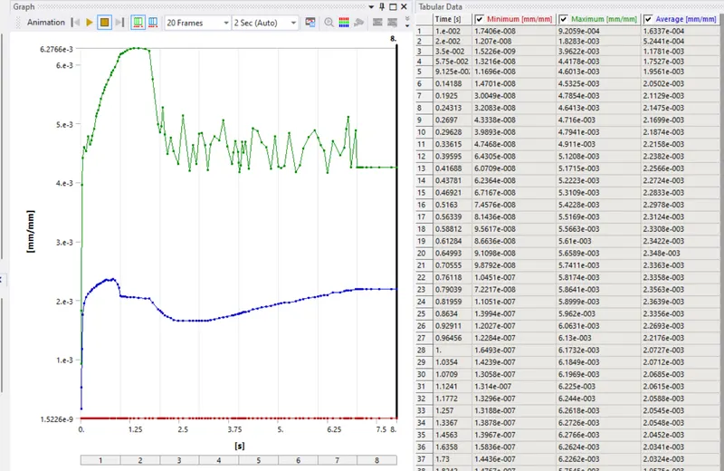
Equivalent Elastic Strain And Graph
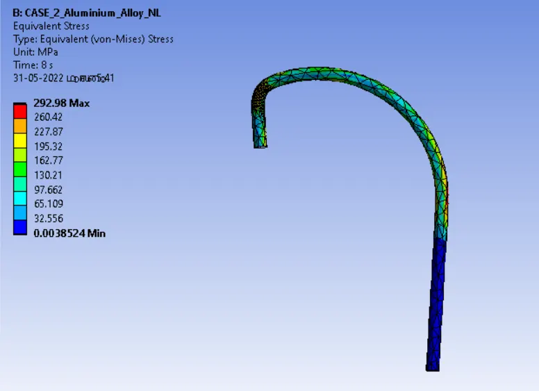
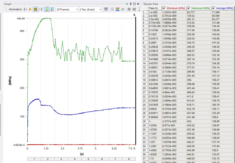
Equivalent Stress And Graph
case= 3
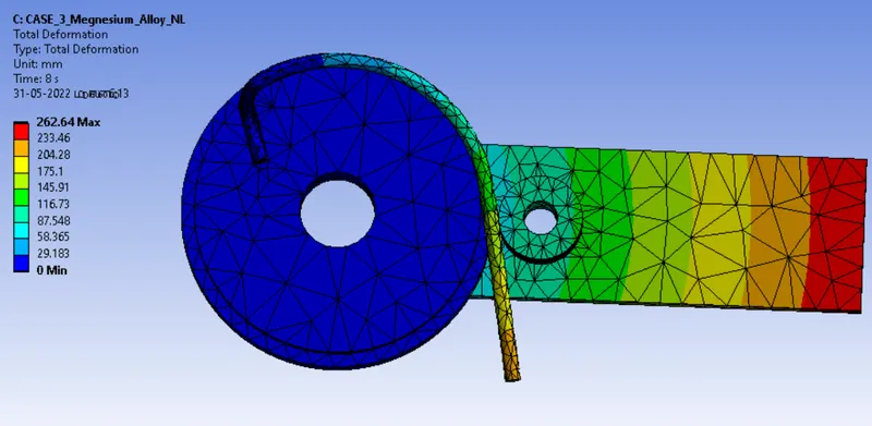
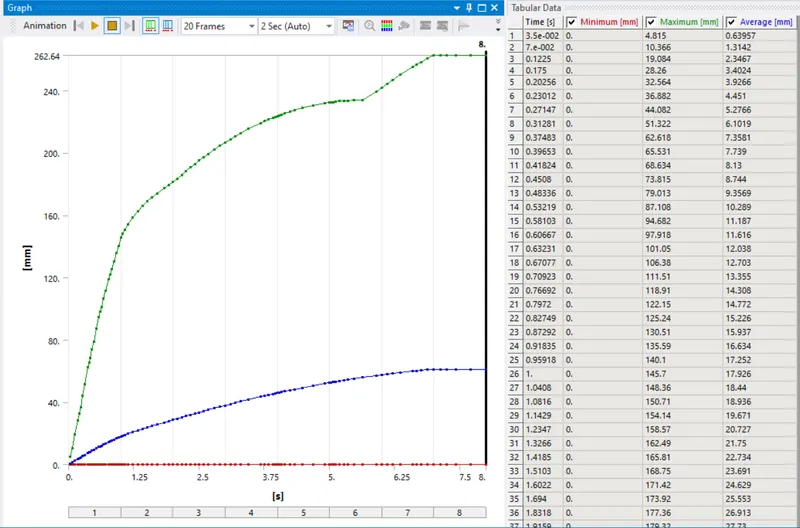
Total Deformation And Graph
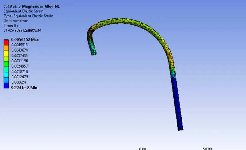
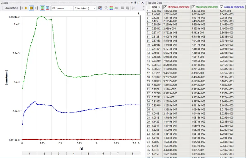
Equivalent Elastic Strain And Graph
Equivalent Stress And Graph
RESULTS
Case= 1,Copper Alloy NL

Case= 2, Aluminium Alloy

Case= 3,Megnesium Alloy

Conclusion:
- We can see above result all three cases are have same values of the total deformations.
- Megnesium Alloy faces high Equivalent Elastic Strain compare to other two materials.
- Copper Alloy faces high Equivalent Stress compare to other two materials, so it's stiffer then other two marterial and can be hard for bending.
- Stiffness is the resistance of a wire to tension or bending. Wires with low stiffness have high elasticity, and their slope is close to horizontal. They can be bent easily, and they return to their to original position when the stress is removed.
- We can use megnesium alloy for their easy bending process