Week 4 -Wire Bending Challenge
Aim: Performing wire bending operation using structural analysis.
Objective:
- Carry out a static structural analysis to find Equivalent Stress and Equivalent Elastic Strain for wire.
- We are using three different materials to perform wire bending.
- Comparing the three results on the basis of the solution.
Procedure:
1) For wire bending analysis, we use the static structural tools in the analysis system toolbox to define the geometry and other input parameters for the same.
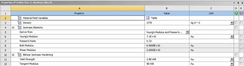
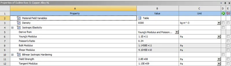
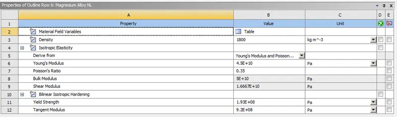
2) In the engineering data we input the material and its properties. In this case, we are using three types of non-linear material and their properties are shown below.
Case 1: Find out the Equivalent stress and Equivalent elastic strain of the wire and compare the results for the Aluminium Alloy NL.
Case 2: Find out the Equivalent stress and Equivalent elastic strain of the wire and compare the results for the Copper Alloy NL.
Case 3: Find out the Equivalent stress and Equivalent elastic strain of the wire and compare the results for the Magnesium Alloy NL.
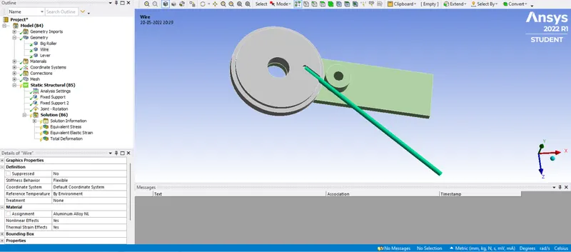
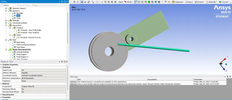
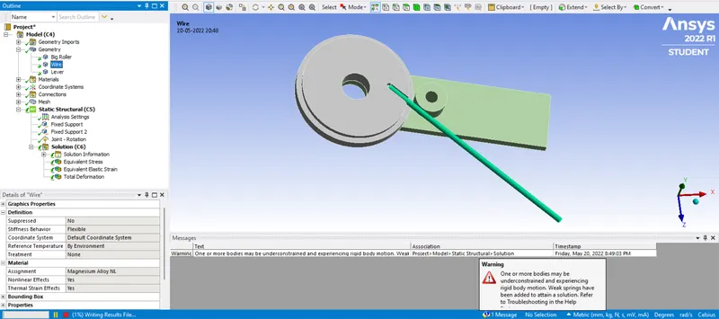
3) Verifying the geometry of the figure.
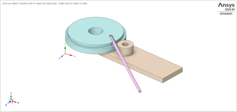
4) In the geometry of the model, the Lever and Big Roller are made up of Structural Steel metal.
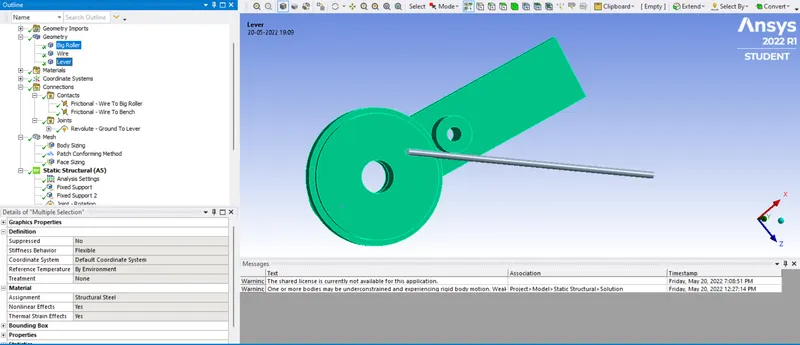
5) In connection, we have to define the contact faces of the geometry by selecting and deselecting contact or target bodies. In contacts under the connection tab, we define the type of contact as frictional contact.
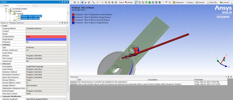
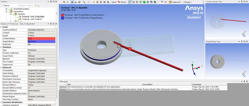
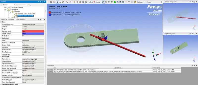
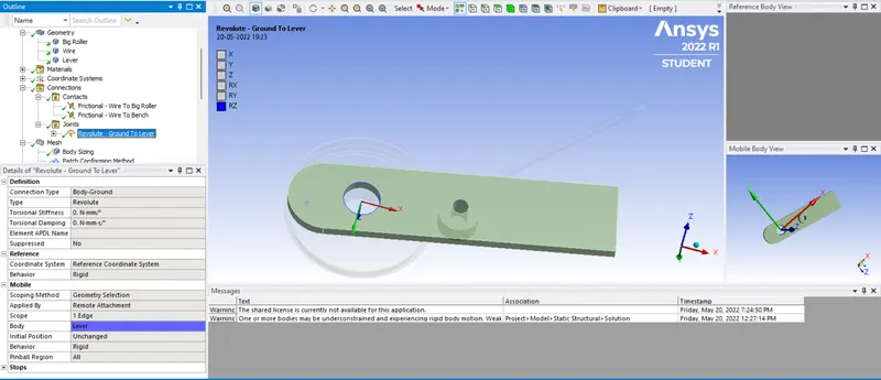
6) Joint is defined for the lever as Connection Type as Body-Grounded and Type as revolute
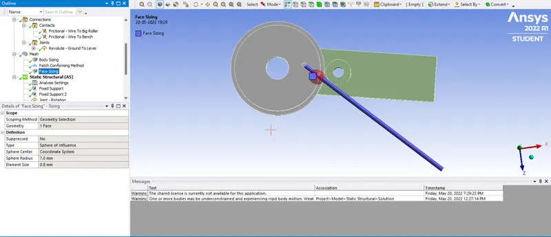
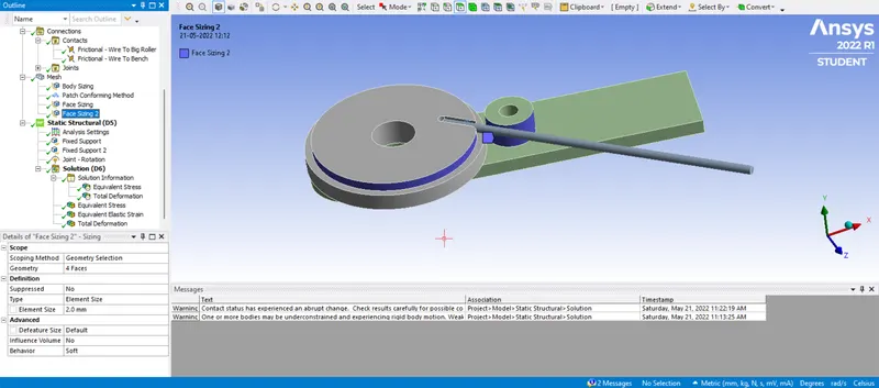
7) By opening the modelling tab, we mesh the geometry with element size as default and finer mesh size where contacts are present. Generating the mesh thereafter by right-clicking on the Mesh icon. Finer mesh is used for the sheet which is going to get deformed and wherever the sheet comes in contact.
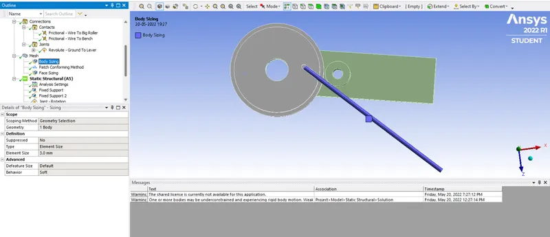
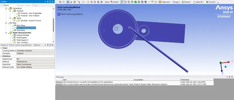
The method used is Tetrahedrons
Face sizing
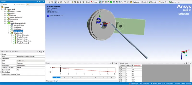
8) We open the analysis setting where we define the Joint - Rotation and Fixed Supports for 8-steps
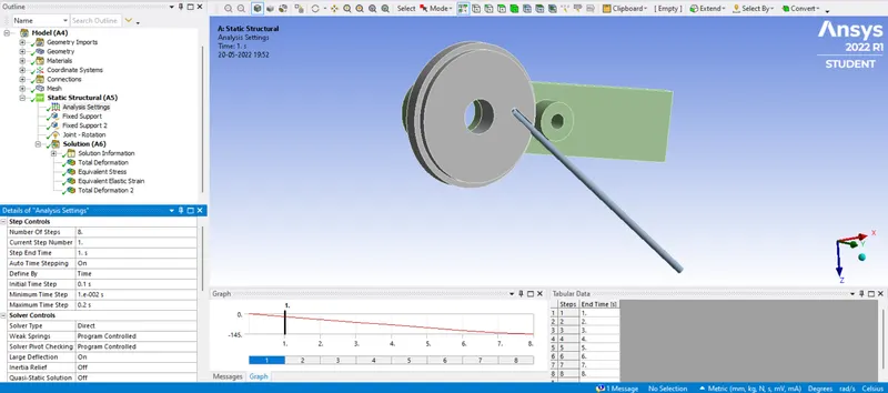
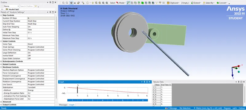
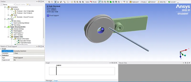
Fixed Support 1: We select the inner rotational face of the big roller
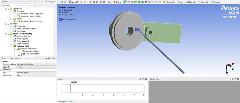
Fixed Support 2: Here we select the face of the wire
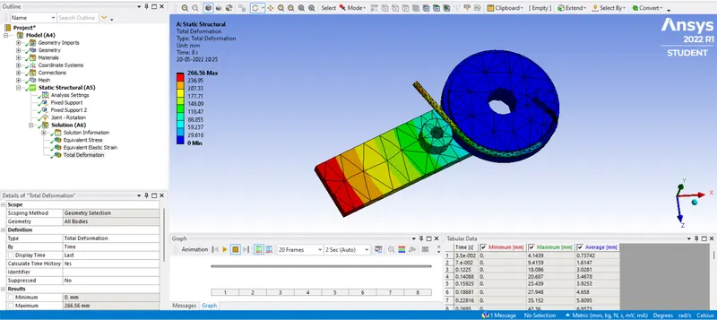
Joint-Rotation is defined for the Lever with Tabular Data as shown in figure
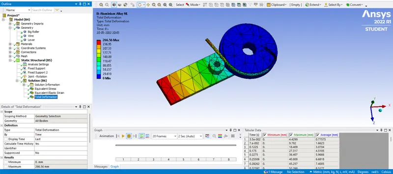
Case 1: Aluminium Alloy NL:
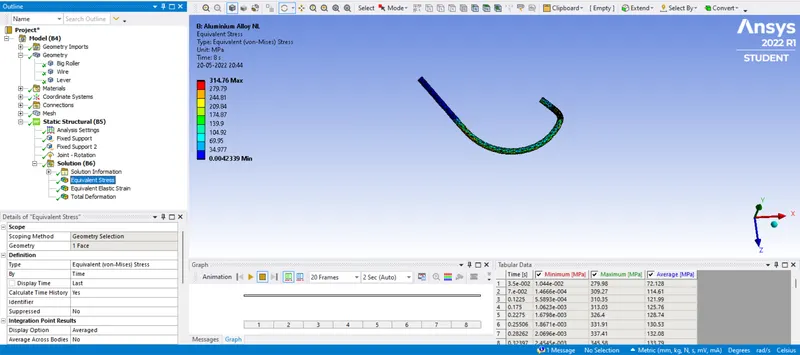
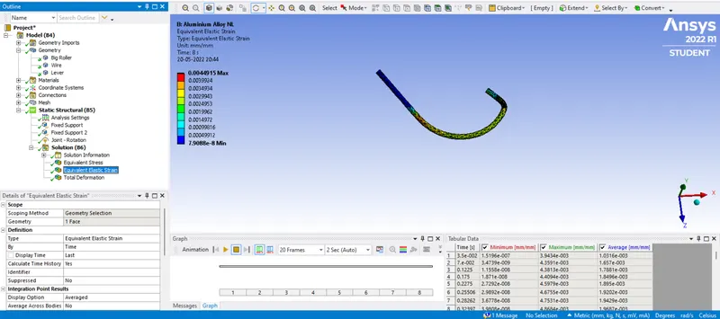
The sheet is selected as Al Alloy NL
Equivalent Stress for wire:
Equivalent Elastic Strain for wire:
Total Deformation:
Case 2: Copper Alloy NL:
The sheet is selected as Cu Alloy NL
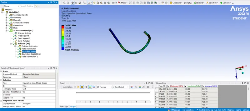
Equivalent Stress for wire:
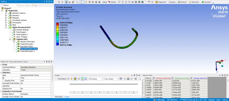
Equivalent Elastic Strain for wire:
Total Deformation:
Case 3: Magnesium Alloy NL:
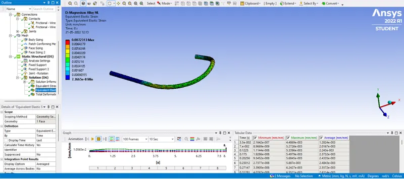
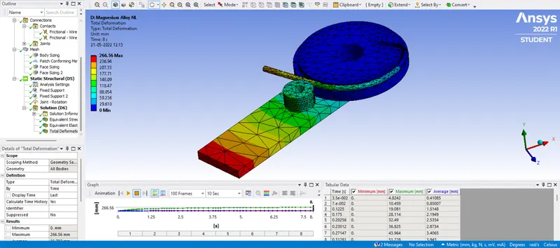
The sheet is selected as Mg Alloy NL
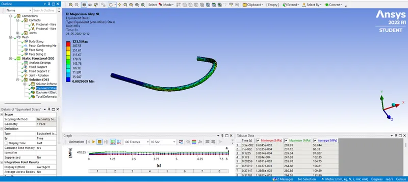
Equivalent Stress for wire:
Equivalent Elastic Strain for wire:
Total Deformation:
Results:
| Materials | Al Alloy Nl | Cu Alloy NL | Mg Alloy NL |
| Total Deformation (Maximum) in mm | 266.56 | 266.56 | 266.56 |
| Total Deformation (Minimum) in mm | 0 | 0 | 0 |
| Equivalent Stress for wire (Maximum) in MPa | 314.76 | 367.02 | 323.5 |
| Equivalent Stress for wire (Minimum) in MPa | 4.2339e-003 | 6.3052e-003 | 2.9609e-003 |
| Equivalent Elastic Strain for wire (Maximum) in mm/mm | 4.4915e-003 | 3.3579e-003 | 7.2313e-003 |
| Equivalent Elastic Strain for wire (Maximum) in mm/mm | 7.9088e-008 | 8.0217e-008 | 7.3665e-008 |
Conclusion:
In copper alloy, we can see more stress compared to the other two metals as the copper alloy is stronger than the other two.
Equivalent Strain is maximum in Magnesium alloy compared to the other two metals.
We can see that the highest amount of stress is generated in the copper alloy wire but it experiences the least amount of strain on average. this explains the higher Young's Modulus exhibited by copper and its alloys in general, compared to those of aluminium and magnesium. This, coupled with its high ultimate strength, conductive and ductile properties, makes it ideal for usage as the material for wires.
From the outputs, we can see that most cases have the highest stress at the fillet of the wheel along which the wire is being bent. This is probably due to stress concentration as a result of the abrupt change in geometry along which the ire was being bent. In addition to that, the point of contact between the lever and the wire also generates comparable stress (probably a result of stiffness), which explains why it's marginally higher in case 2.
Note: google drive link is provided below in a text file. Please check the link for the model.
Thank You...