Week 4- Rolling operation
SHEET ROLLING
Aim
To model a simple sheet rolling system and determine the thickness reduction, stresses on sheet metal and deformation.
Theory
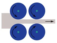
In metalworking, rolling is a metal forming process in which metal stock is passed through one or more pairs of rolls to reduce the thickness, to make the thickness uniform, and/or to impart a desired mechanical property. The concept is similar to the rolling of dough. Rolling is classified according to the temperature of the metal rolled. If the temperature of the metal is above its recrystallization temperature, then the process is known as hot rolling. If the temperature of the metal is below its recrystallization temperature, the process is known as cold rolling. In terms of usage, hot rolling processes more tonnage than any other manufacturing process, and cold rolling processes the most tonnage out of all cold working processes. Roll stands holding pairs of rolls are grouped together into rolling mills that can quickly process metal, typically steel, into products such as structural steel (I-beams, angle stock, channel stock), bar stock, and rails. Most steel mills have rolling mill divisions that convert the semi-finished casting products into finished products.
Procedure
- Start a new static structural model in ansys and import the model
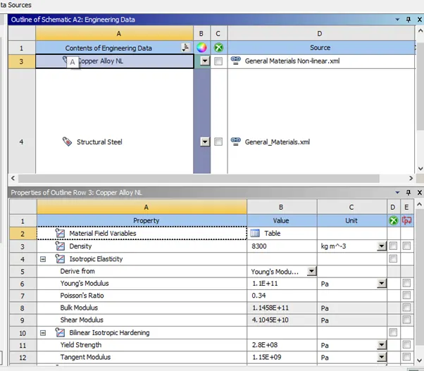
- Add the nonlinear materials of copper alloy located in non linear materials.
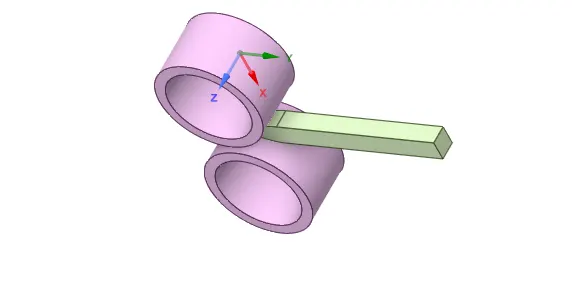
- Open Ansys space claim to modify the geometry to our requirements.
- Increase the length of the sheet metal by 60mm and reduce the size by 8mm on each side.
- Open this model in ansys mechanical.
- Check that the materials were properly assigned to the model
- Flip the contacts and targets and select all the faces of the sheet metal that come into contact with the roller properly.
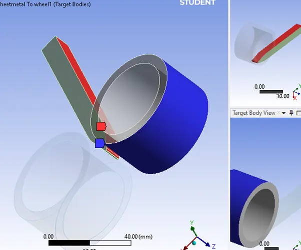
Do the same for the other contact
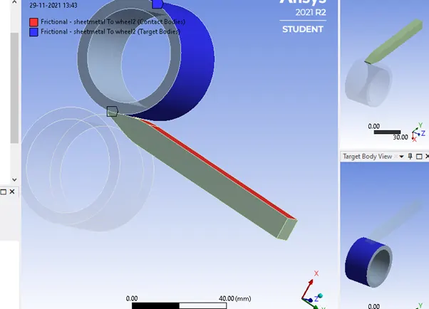
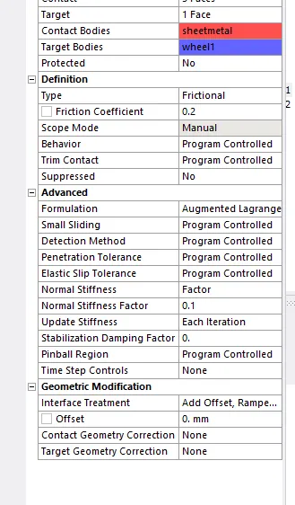
- Change the contacts to frictional and set friction coefficient to 0.2
- Change the contact properties as shown
- Create 2 Body-ground rotational joints , one for each wheel.
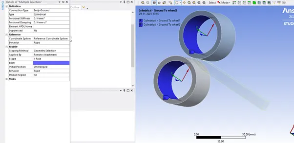
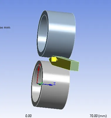
- Use the reference coordinate system to change the z axis if it isn’t as shown in the above figure.
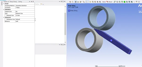
- In mesh, create a sizing group for the sheet and set mesh size to 2mm.
- Define the displacement of the sheet metal along the y axis, choose the opposite face shown as well.
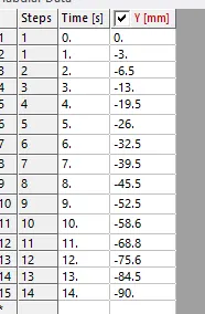
- Set displacement in y as tabular and give small but steady increases in displacement
- Define the rotation of the wheels along the z axis.
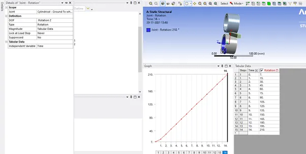
- Do the same for the other wheel but the values should be negative to get the desired movement.
Analysis Settings
Set the analysis settings as shown.
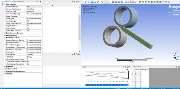
Set your output blocks as shown
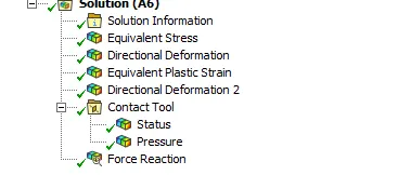
- Directional deformation has the 2 faces along the z axis to determine thickness reduction
- Directional deformation 2 has the tip of the sheet to determine total displacement
Post Processing
Sheet rolling
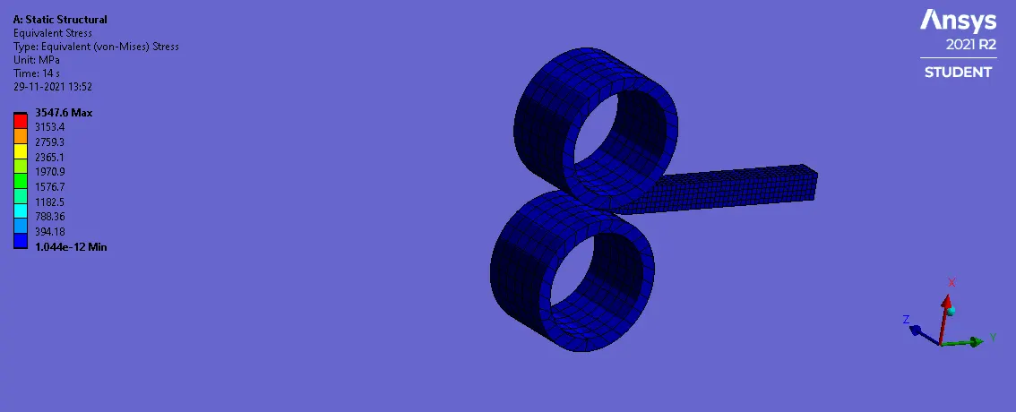
Tabulated Results
|
Material |
Copper |
|
Maximum Stress (MPa) |
3547.6 |
|
Thickness Reduction(mm) |
6.74 (negative z) |
|
Plastic Strain |
2.2067 |
|
Maximum Pressure on Sheet metal (MPa) |
4547.6 |
|
Directional Deformation (mm) |
90 |
It can be seen that the thickness of the sheet metal reduces by approximately 6.74 mm in the negative z axis.
The plastic strain reaches a maximum of 2.2067 with a maximum stress of 3547.6MPa on the sheet metal.
The directional deformation reaches a value of -90mm, indicating that the sheet metal has moved 90mm in the negative y axis.
Conclusion
In metalworking, rolling is a metal forming process in which metal stock is passed through one or more pairs of rolls to reduce the thickness, to make the thickness uniform, and/or to impart a desired mechanical property
In this project, a simple metal rolling setup was modelled and run to determine the thickness reduction and the stresses experienced by the sheet metal.