Week 4- Rolling operation
OBJECTIVE :-
Simulate the rolling operation on a workpiece made of copper. The model will be provided to you. Increase the length of the workpiece by 60mm and decrease its size on both sides by 8mm. Run the simulation for 14 steps and you can give small but random values for the displacement. Ensure that the edge of the workpiece is displaced by 90mm.
Find out the
- Equivalent stress for the whole setup
- Equivalent Plastic strain for the workpiece
- Directional Deformation in the Z axis for the workpiece
- Prove that the workpiece has displaced by 90mm.
CASE SETUP
- open ansys workbench and drop down the static structure onto the project window.
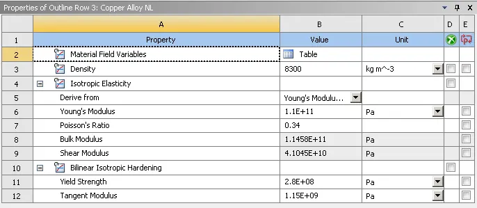
- Select Copper Alloy material from Engineering data sources with required properties.
- Import the geometry.
- Edit geometry in space claim module such that change dimensions of model as per given dimensions ( Increase the length of the workpiece by 60mm and decrease its size on both sides by 8mm.)
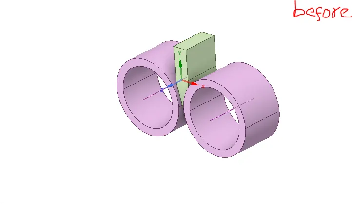
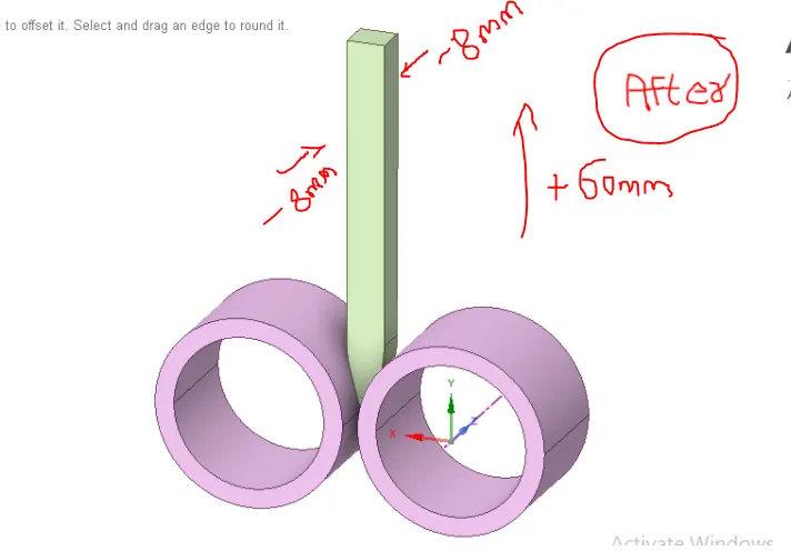
- After completion of geometry modifications
- Open the mechanical module
- Rename the components as wheel1,wheel2, workpiece
- Assign structural steel for both wheels and copper alloy for workpiece
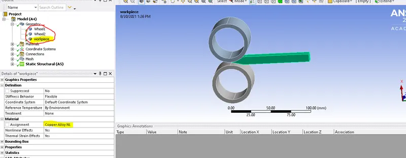
Copper Alloy NL - properties
Contacts
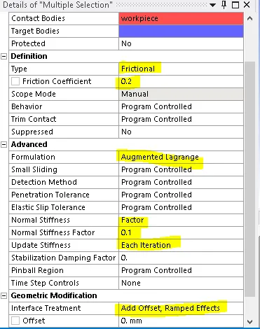
- create a two frictional contacts (punch - sheet and sheet - die) with a frictional coefficient of 0.2
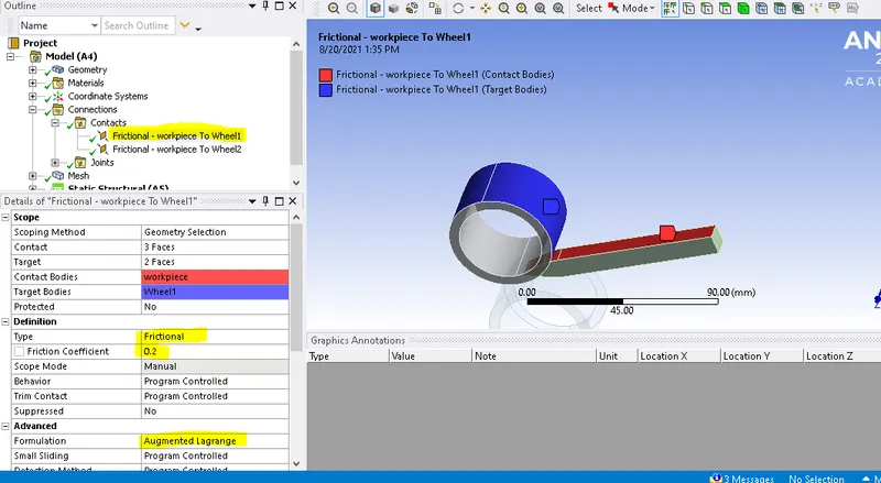
contact between Workpece and wheel1
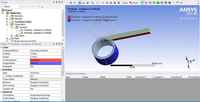
contact between Workpece and wheel2
- Details of both frictional contacts
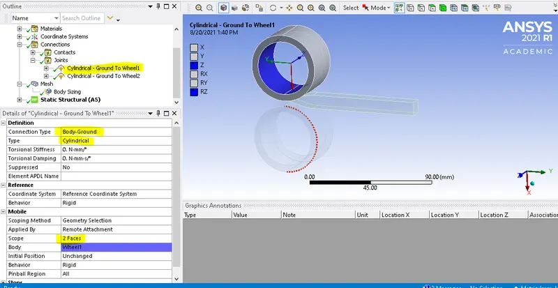
Joints
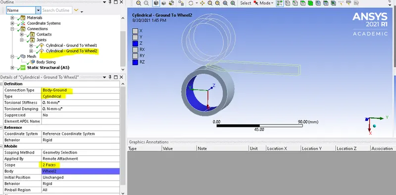
- create a two cylindrical joints (b/w wheel1,wheel2 and workpiece) with Body -Ground connection type, rotating in z- dircection
MESH :-
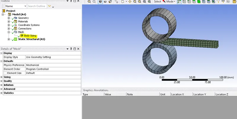
Generated a default mesh for both wheels and 4mm mesh for workpiece using body sizing option.
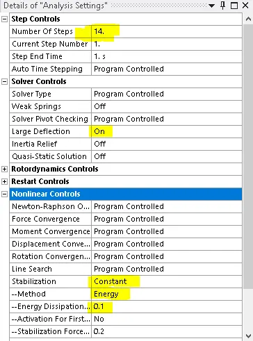
- Analytical settings - this analysis setup for 14 steps, this doesn't control time step, but it is only indication of points where boundary conditions change. the time step is auto controlled by minimum ,initial maximum and time steps.
BOUNDARY CONDITIONS
- Displacement for workpiece (90mm in 14steps)
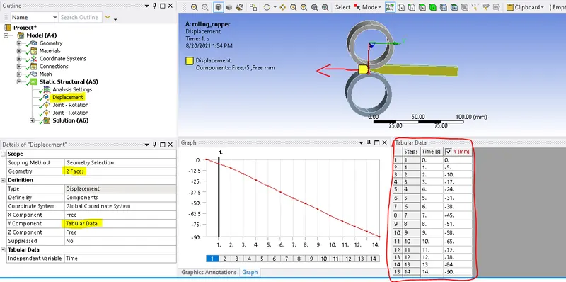
- Create a two joint loads on wheels in Z- direction , make sure both wheels should be movie in opposite direction.
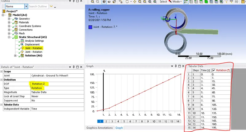
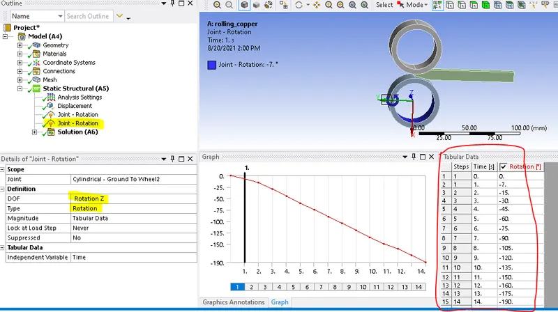
- Find out the
- Equivalent stress for the whole setup
- Equivalent Plastic strain for the workpiece
- Directional Deformation in the Z axis for the workpiece
- Prove that the workpiece has displaced by 90mm.
RESULTS
Equivalent stress for the whole setup
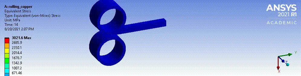
Equivalent stress for the whole setup
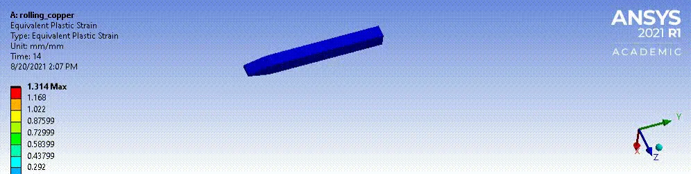
Equivalent Plastic strain for the workpiece
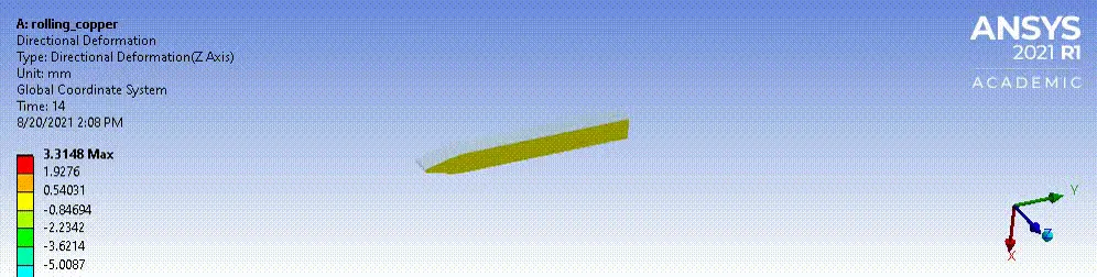
Directional Deformation in the Z axis for the workpiece
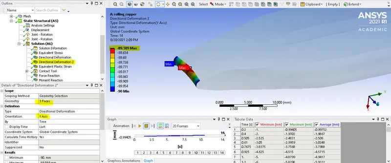
- Prove that the workpiece has displaced by 90mm - in boundary conditions we given 90mm as displacement for workpiece so check is it reached 90mm or not, so that give directional deformation to the tip of the workpiece
- in our case workpiece reached 89.6mm for 90mm so it is Proved that the workpiece has displaced by 90mm.
Conclusion
The overall structural analysis to simulate the rolling operation on copper workpiece of 90mm length is performed and proved.