Week 4- Rolling operation
OBJECTIVE:
To simulate rolling operation on a workpiece made of copper alloy and find out the required output in ANSYS.
PROCEDURE:
Open Ansys Workbench and choose static structural. In the Engineering data, let the material be structural steel and also choose Copper Alloy non-linear from General non-linear material with default values.
MATERIALS USED:
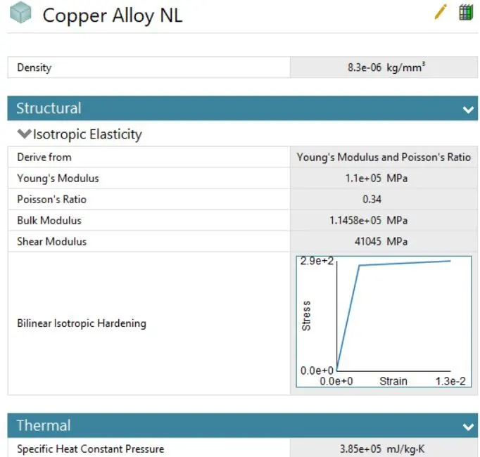
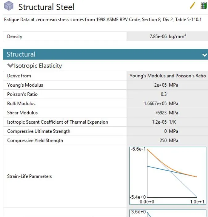
- For the geometry, right-click and import the given Copper_Rolling.stp and open with space claim.
- Using the 'Pull' option sketch edit elongate the workpiece length to 60mm and from either side reduce 8mm thickness.
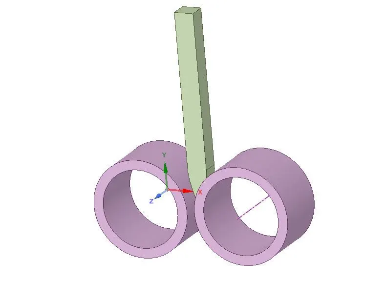
- Now in the workbench goto Model -> Edit, in the model window check the Geometry for the material and assign Structural Steel
to the wheel and Copper Alloy NL to the workpiece.
CONTACTS:
For contacts, first, flip contact/target for both the contacts and select 'rename based on definition', for each contact select the required target and contact bodies than for both contact assign the contacts Type= Frictional and Friction coefficient= 0.2, Formulation= Augmented Lagrange, Normal Stiffness= Factor, Normal stiffness factor= 0.1, update stiffness= each iteration and Interface Treatment= Add Offset, Ramped Effects.
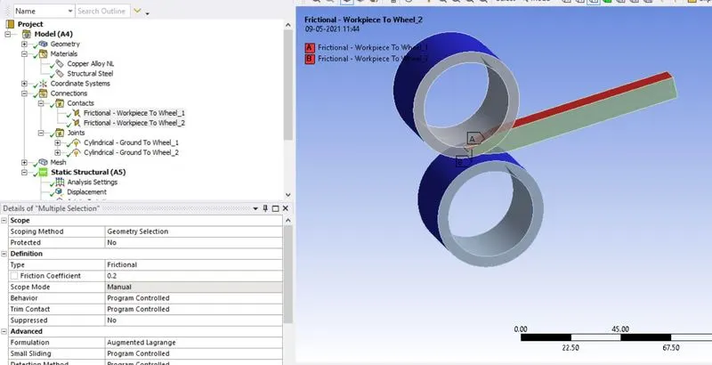
JOINTS:
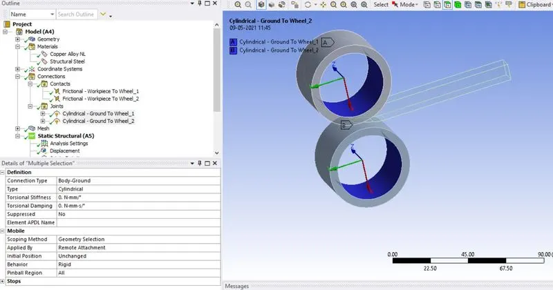
For joints, the 2 wheels will have rotation along the z-axis so joints are created for the 2 wheels by Connection -> Joint -> Body to ground -> Cylindrical, click on Scope= select inner face of the wheel and also reverse the z-axis by clicking on Coordinate system= Reference coordinate system.
MESH:
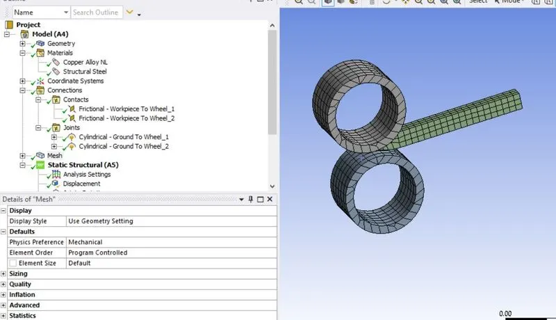
For mesh, as the scope of the result is for workpiece it should have meshed with a smaller element size 2 mm for that right-click on mesh select body sizing and choose the geometry as workpiece and element size 2 mm, click on generate the mesh.
ANALYSIS SETTINGS:
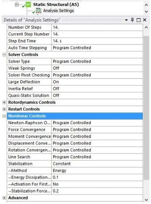
For the analysis setting, the number of steps will be 14 select all the steps and provide Large Deflection= on, under Non-Linear Control, stabilization= constant, method= energy and energy dissipation= 0.1.
Now apply displacement to the workpiece by selecting the 2 sides of it in the y-axis in tabular format such that the workpiece travels 90mm.
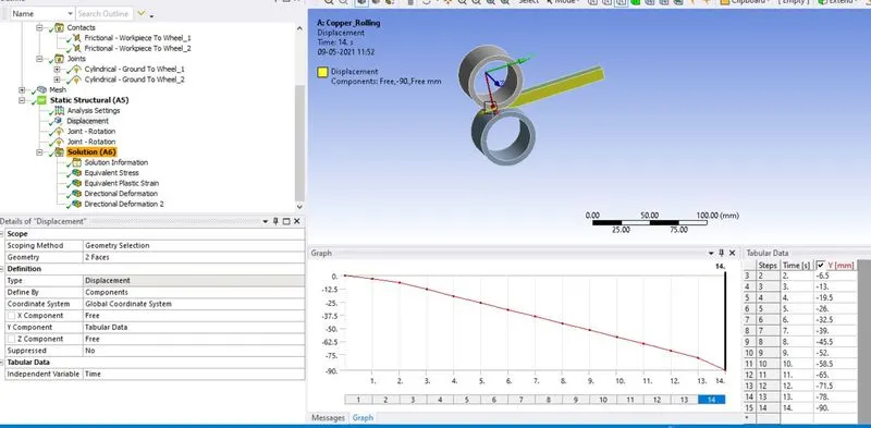
For the 2 wheels apply the joint load, type= rotation and dof= rotation z and magnitude= tabular such that one wheel rotates clockwise and the other anticlockwise.
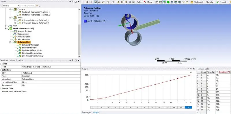
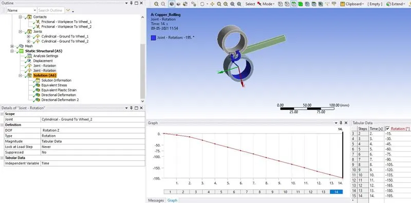
RESULTS:
Provide the required output request for the solution like:
Equivalent stress for the whole setup:
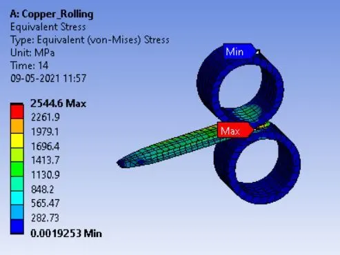
Equivalent Plastic strain for the workpiece:
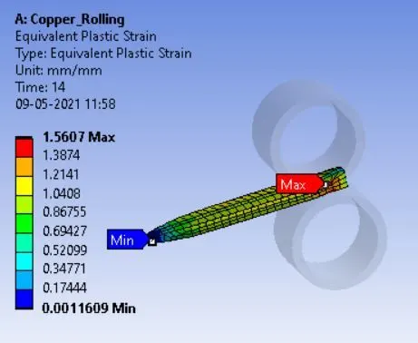
Directional Deformation in the Z-axis for the workpiece
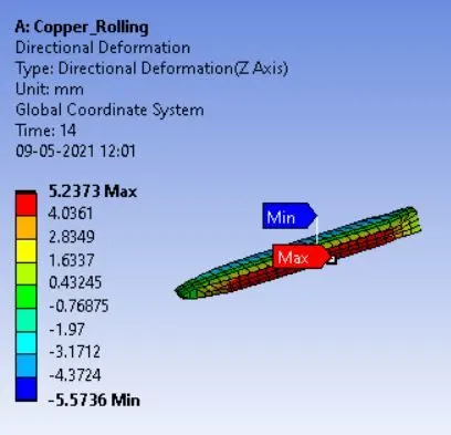
After the rolling operation, the workpiece thickness is increased along the Z-axis the maximum deformation is about 5.2584 mm.
Prove that the workpiece has displaced by 90mm
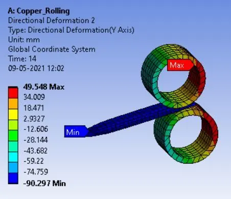
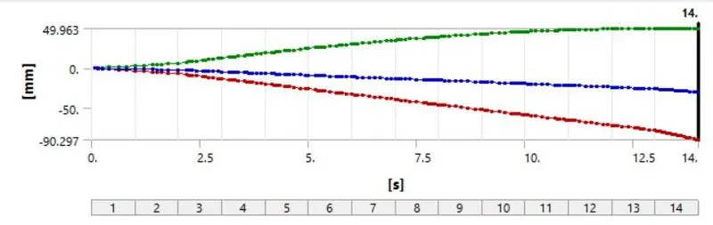
From the above directional deformation simulation and the graph it can be observed that the workpiece has displaced by near to 90mm the maximum displacement observed is -89.562 mm along the Y-axis.
CONCLUSION:
So by completing the analysis of the rolling operation of the workpiece of copper alloy non-linear it can be observed that the maximum equivalent stress experienced by it is about 3245.6 MPa while the thickness along Z-axis is increased maximum of 5.2584 mm as the workpiece is displaced along the y-axis to the maximum displacement of -89.562 mm.