Week 4- Rolling operation
Objective:
The objective is to simulate a workpiece made of copper alloy go in between two rollers. The length of workpiece needs to be extended by 60mm and decrease its size on both sides by 8mm. Also the simulation has to run on 14 steps for displacement such that the edge has displaced a total of 90mm.
Setup:
Firstly we need to add copper alloy material to the Engineering Data. To do that open engineering data and going to Engineering Data Sources we add copper alloy from the General Non-Linear Materials list. After adding the material we import the geometry and then open it in space claim. Once the model loads in Space claim we go under the design tab and select the pull option. In order to increase its length we select the free end surface and extend it upwards upon which a small dialog box appears where the value of 60mm is inserted. Once the workpiece is extended to the desired value the sides are slected using the pull menu and is dragged to the inside upon which a dialog box appears to which we enter the value of 8mm. Doing the same for the other side we now have the model according to the requirment of the question. Once this is done the model is updated and the Mechanical module is opened. Upon opening we first rename the parts as Roller 1, Roller 2 and Workepiece respectively. Assign the material copper alloy to the workpiece and the rollers be structual steel. Moving onto to the connections the already default contacts are flipped and renamed based on definition. Selecting the contacts indicidually the surfaces the roller will come in contact with the workpiece is selected as Contact and the roller surface is assigned as the target. The same is done with the other roller and its corresponding workpiece surfaces. Both the contacts are made frictional with a frictional coefficient of 0.2. Change the formulation to Augmneted Lagrange and change the normal stiffness to factor and change the factor to 0.1. Let all the other settings be default. Then comes the definition of two cylindrical joints for each roller. For the geometry selection of cylindrical joint for both rollers we select the inner surface of the roller. Flip the z axis for both joints and make sure the reference coordinates's Y axis is pointing away from the workpiece. Both joints are grounded. For meshing the whole workpiece is selected to give a mesh size of 4mm and tetrahedron elements. While the outer roller surface is given a mesh of 2mm. Going inot analysis settings we give 14 steps. Selecting all the 14 steps switch on the large deflection and going inot non-linear controls change the stabilisation to constant with energy dissipation given the value of 0.1 rest all are left at default values. After that a displacement is give with the sides of the workpiece selected as geometry the value of displacement is given in tabular form. The values are -3,-6.5,-12,-20,-25.5,-30,-42,-49.5,-54,-62,-69,-75,-82 and -90. All the value are in negative as the displacement occurs in the negative Y direction. After giving the displacement the joints are given loads. Roller one is given positive value while the other is given negative value so as to rotate it in opposite direction. The rotation values are given and the orientation is given in the Z direction. The values are 7,15,30,45,50,65,75,80,95,120,135,150,165 and 180. For roller two the same values are inserted but just in negative value. From solution select Equivalent stress for whole stup, Equivalent plastic strain only for the workpiece, Directional deformation along z axis for the workpiece and Directional deformation for the workpiece along Y axis to prove that the Workpiece displaced by 90mm.
Result:
Equivalent Stress for the whole setup:
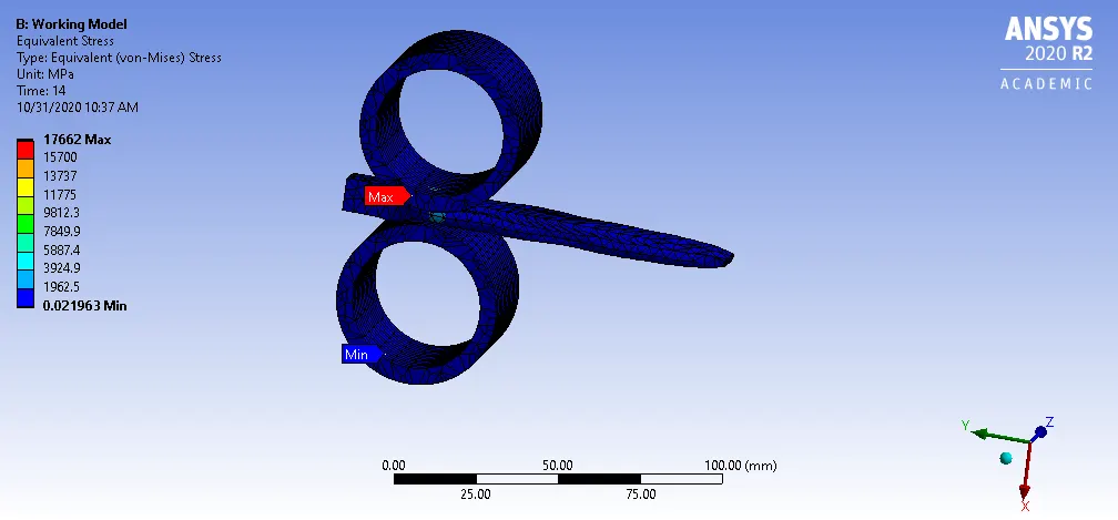
Equivalent stress for the whole setup shows that the maximum stress occured at the point of contact with the roller and workpiece which is 17662 MPa.
Equivalent Strain for the workpiece:
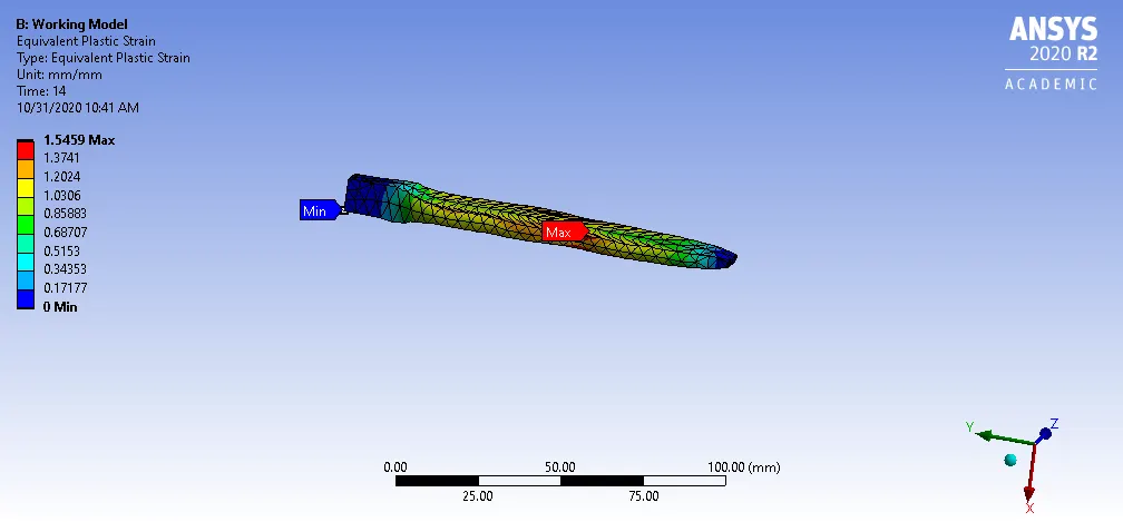
The maximum plastic strain is 1.5459mm/mm which occurs at one of the top edges.
Directional Deformation in Z axis for workpiece:
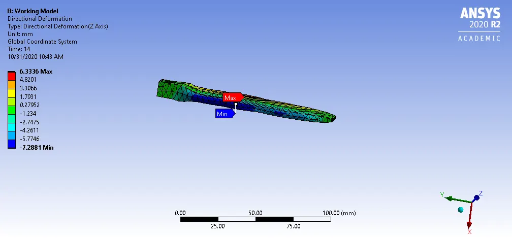
The maximum deformation in z axis for the workpiece is 6.3336mm which occurs at the top part of the workpiece.
Proof workpiece has moved 90mm:
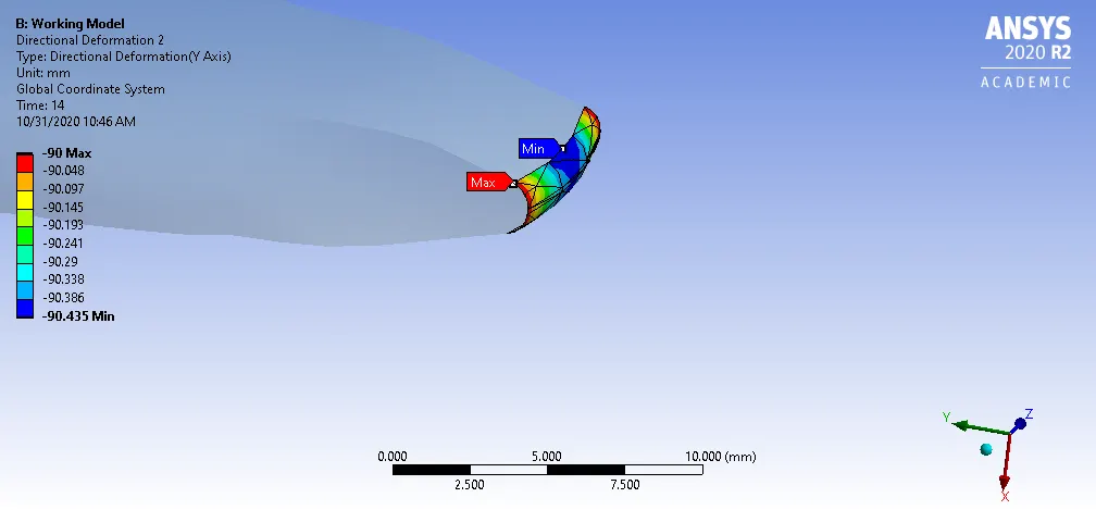
In order to prove the workpiece has moved a total of 90mm a directional deformation along the Y axis for the workpiece with its leading edge being selected as the measuring geometry is setup. And as seen above the maximum deformation shown is 90mm which is at the leading edge proving the whole workpiece has moved a displacement of 90mm.
| Maximum stress of setup (MPa) | 17662 |
| Maximum Plastic Strain in workpiece (mm/mm) | 1.5459 |
| Maximum deformation in z axis for workpiece (mm) | 6.3336 |