Week 3 Sheet metal Bending challenge
SETUP:
For the setup the geometry was first imported into the spaceclaim. Going to engineering materials a duplicate of Aluminium Alloy was made to which properties were assigned. Other materials like Copper alloy and Magnesium alloy was added from the General Non-Linear Materials group. Once the geometry was updated and all the materials have been added updation of the model is done. After opening the Mechanical model windown we assign name to the parts as Punch, Die and Sheet respectively. While selecting the sheet we also change the material assigned to the required one wether it be Aluminium, Copper or Magnesium in Case 1, Aluminium in Case 2 and 3. After assigning materials we go into contacts and delete the computer generated contacts. Manually adding the contacts the first pair includes the bottom three surface of the punch which will be in contact with the sheet as the contact bodies and the upper surface of the sheet as the target bodies. Manually defining the other set of contact includes the bottom part of the sheet as the contact body and the top 7 surfaces of the die as the target bodies. Both the contacts are assigned as frictional with coefficient of friction as 0.1 for case 1 and 3 while the value is 0.19 for case 2. The behviour for all models are kept as asymmetric, formulation is kept as Augmented lagrange, the Normal stiffness is changed to factor and normal stiffness factor is given a value of 0.1, finally the interface treatment is kept at Add offset, No ramping. Moving onto the mesh the whole body of punch and die is given a mesh size of 4mm. The mesh size of sheet is kept at 1mm and also the method is changed to tetrahedrons for sheet only. The mating surfaces on the punch and die ( which are 10 in total) is given a mesh of 2mm. Once the mesh is done the Analysis settings are opened where the number of steps is given a value of 10. Selectin all the 10 steps change the solver type to direct and seitch on the large deflection. Additionally Stabiliztion is changed to constant under Nonlinear Controls ( the energy dissipation value is changed to 0.1). Once this is done displacement is given. There is a total of 3 displacements. For the first displacement the top three surface of the punch is selected and the values of all 3 axes are given in tabular column. The X and Z axis are kept 0 while the y axis the values are given -0.5,-1.5,-3,-6,-9,-12,-13.5,-12,-9,-8 from step 1 to 10 respectively. The next displacement is given by selecting all the surfaces of the die except the mating surfaces and here all axes are given in tabular value but only the Y axis has value the others are left 0. The last two steps in Y axis are given -1.5 and -3 others all are left 0. Now selecting the faces facing Z axis on the sheet we keep all the other axes free except z which is given a value of 0. After this is done going into the solution and selecting directional deformation, equivalent strain and equivalent stress is done. Change the aaxis of directional deformation to Y axis. Also selecting the sheet as the only geometry for all the solution would give the result of sheet alone.
Case 1:
Aluminium Alloy:
Directional Deformation along Y axis
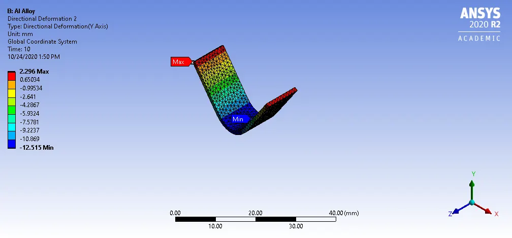
The Al sheet had a maximum deformation of 2.296mm which was at the end of the sheets. The minimum deformation was at the center of the sheet.
Strain:
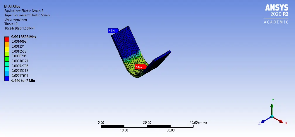
Maximum strain for Al alloy sheet is 0.0015826 mm/mm and the occurance was at the middle of the sheet as well.
Stress:
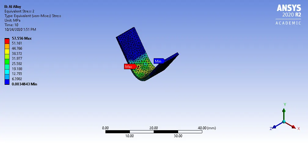
The maximum stress occured in Al sheet is 57.556 Mpa which occured around the center of the sheet.
Copper Alloy
Directional Deformation Y Axis:
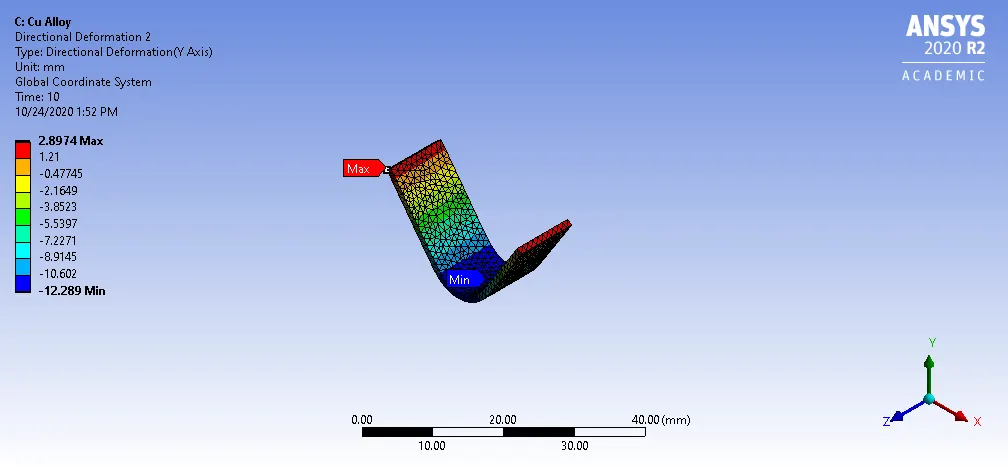
The maximum deformation for Copper alloy is 2.8974mm maximum and the position is at the ends.
Strain:
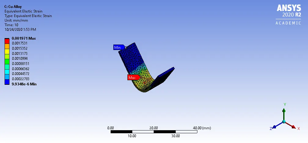
The maximum strain is developed at the center which is 0.001971 mm/mm.
Stress:
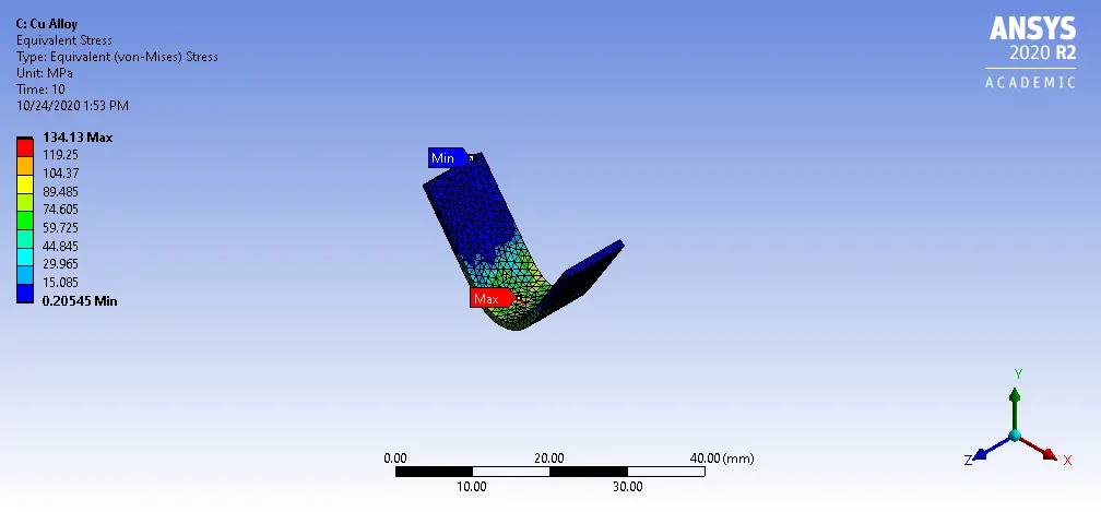
The maximum stress is developed at the center which is 134.13 MPa.
Magnesium Alloy:
Directional Deformation along Y axis:
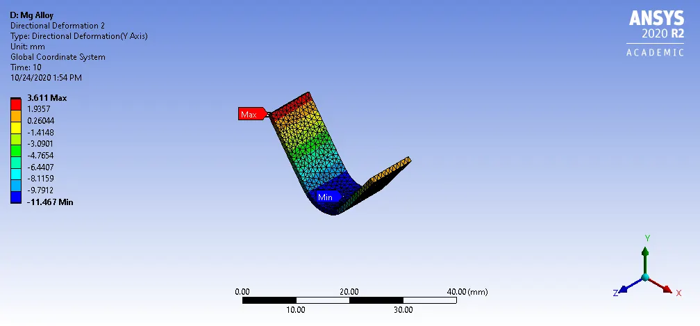
The maximum deformation is at the ends which is 3.611 mm.
Strain:
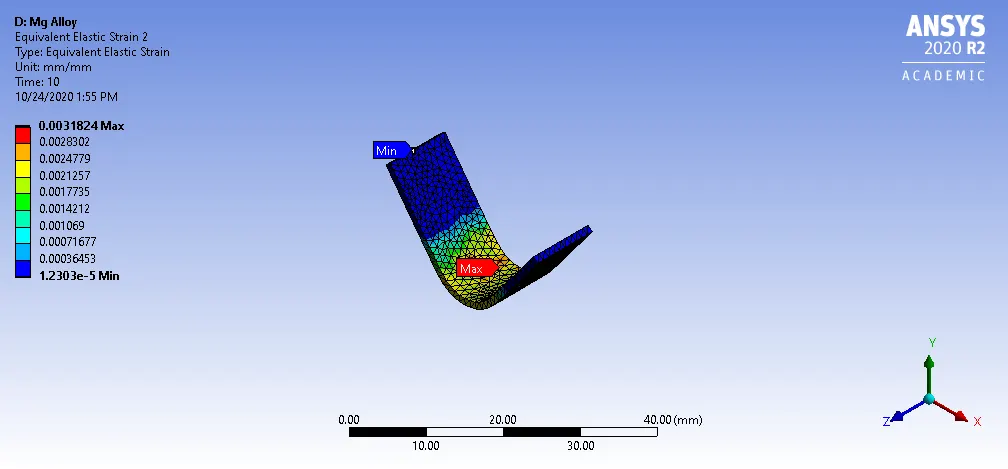
The maximum strain occurs at the center which is 0.0031824 mm/mm.
Stress:
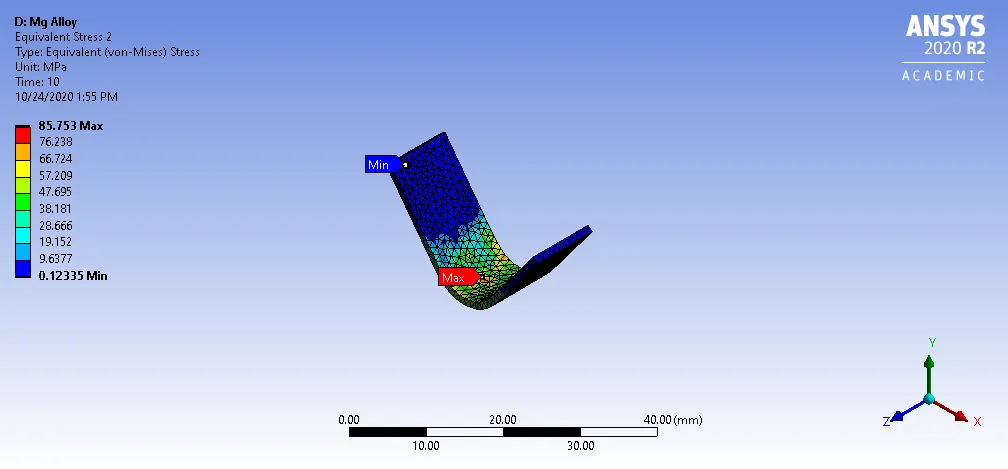
The maximum stress is developed at the center which is 85.753 MPa.
Conclusion:
| Material | Aluminium Alloy | Copper Alloy | Magnesium Alloy |
| Directional deformation (y axis, mm) | 2.296 | 2.8974 | 3.611 |
| Maximum Strain (mm/mm) | 0.0015826 | 0.001971 | 0.0031824 |
| Maximum Stress (MPa) | 57.556 | 134.13 | 85.753 |
The maximum deformation occurs in magnesium alloy followed by copper and last by aluminium. Magnesium is the most deformable material among the lot. Magnesium also has the highest strain followed by copper and then aluminium. Meanwhile maximum stress occurs in copper followed by magnesium and finally by aluminium. So the magnesium deforms the most but has comparitively lower stress value, while aluminium deformed the least and developed the least stress.
Case 2:
In case 2 the frictional coefficient between contacts is kept at 0.19 and the same results are plotted for the material of aluminium alloy. The mesh size is kept the same only the firctional coefficient is changed.
Deformation in Y axis:
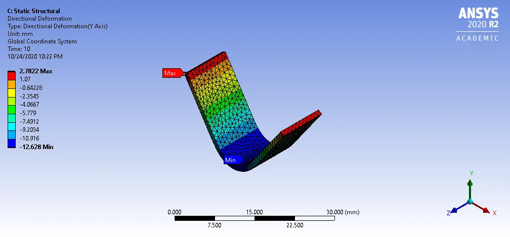
The maximum deformation is 2.7822 mm which occurs at the ends of the sheet.
Strain:
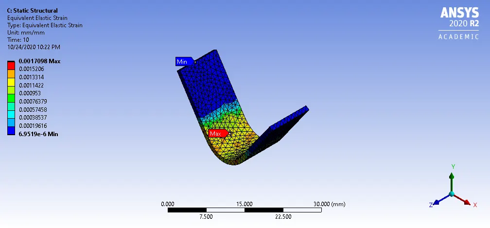
The maximum strain is developed in the centeral area which is 0.0017098 mm/mm.
Stress:
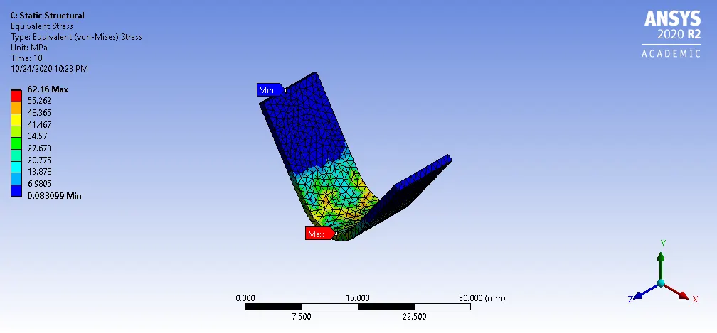
The maximum stress is developed at the center of the plate which is 62.16 MPa.
Comparision:
| Frictional Coefficient | 0.1 | 0.19 |
|
Deformation along Y axis (mm) |
2.296 | 2.7822 |
| Maximum Strain (mm/mm) | 0.0015826 | 0.0017098 |
| Maximum Stress (MPa) | 57.556 | 62.16 |
With the increase in the frictional coefficient all the parameters compared here gained an increase. This was expected as higher frictional coefficient leads to an increase in frictional force leading to higher stress developed and increased deformation.
Case 3:
Here the task was to refine the mesh of the sheet by staying within the academic limit and to compare the results with that of case 1. Again the material used for comaprison is Aluminium.
Directional Deformation along y axis:
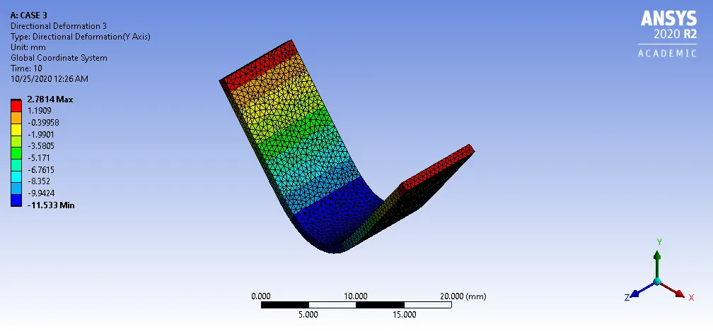
The maximum deformation is at the ends which is 2.7814mm.
Strain:
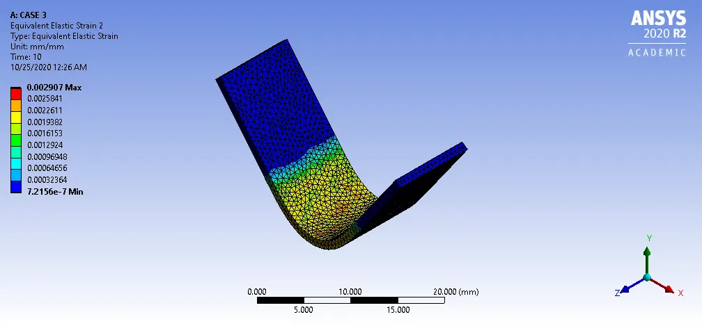
The maximum strain is developed near the center which is 0.002907 mm/mm
Stress:
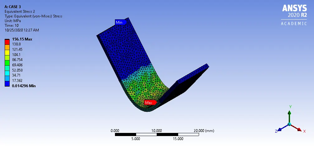
The maximum stress developed is 156.15 MPa.
Comparison:
| Mesh size (mm) | 1 | 0.6 |
| Directional deformation along y axis (mm) | 2.296 | 2.7814 |
|
Strain (mm/mm) |
0.0015826 | 0.002907 |
| Stress (MPa) | 57.556 | 156.15 |
So as the mesh size decreased we can see an increase in value of all the results that are compared here. On trying different mesh sizes the mesh size of 6mm was selected as it was the least possible size to run without exceeding the licnese limitation. The finer the mesh the more accurate the result we get but after a certain poin going down on the mesh size would not give much difference in result but would simply increase computation time.