Week 2 Railwheel and Track
OBJECTIVE:
To apply load of 1e+5 N on a railway wheel shaft to find its deformation, Equivalent stress and the life under the load along with 5 times the load value (5e+5 N) on railway shaft and its deformation, Equivalent stress and life. After getting the results of both cases a comparison should be made.
Case 2: To implement a user defined result to calculate the total deformation and to find the result. Later it needs to be checked to ssee if it is the same as that of the inbult result obtained by Ansys for a load of 100000N.
SETUP:
The geometry is first imported into the file. Once it is loaded the model is updated. Once the model is updated open the model section. Now we will name the models as Rail, Wheel and Shaft accordingly by right clicking the models under the geometry section. Once they are renamed all the elements are assigned structural steel as material. Then goin into contacts initial the contacts are flipped. After that the wheel to rail contact is made frictional with a frictional coefficient of 0.3, all other settings are left as default. The next contact shown is the shaft to wheel which is assigned frictionless and all other settings are kept default. Joints are inserted to give translational motion on the shaft, to keep the rail fixed and to make the wheel move in a single plane by giving a planar joint to the wheel. Once all the joints are defined meshing is done. The overall mesh size is given 50mm and face sizing is applied to the contact region between wheel and rail with a mesh size of 35mm. This gives a total number of elements at 6578 and total number of nodes at 13125. Next moving to analysis settings the number of steps are changed from 1 to 5. For the first step auto time step is program controlled and for steps 2 to 5 the auto time step is on as well as carry over time step. Let it be defined by time and the minimum time step is set at 1e-3 s and the maximum time step is set at 0.1 s. For all the steps large deflection is turned on, the solver type is set to direct and all the output controls are set to yes. After this is done a join load of diplacement is given for the wheel to rail joint. In the tabular column the values are given for steps 1 to 5 from 100 mm to 500 mm with 100mm increment in each step. A bearig load is given to the surface where the shaft is in contact with the wheel the bearing load is given according to the case ( Case 1: 100000 n and 500000n, Case 2: 100000 N). The required solutions are selected which are Total Deformation, Equivalent Stress, Life (from fatigue tool) and User Defined Result for case 2. This setup is ismilar for both cases except the addition of user defined data for 100000N setup.
CASE 1:
The images are in the order of 100000 N followed by 500000 N
Deformation :
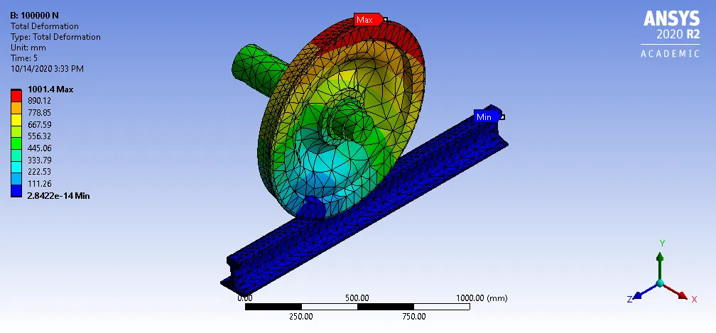
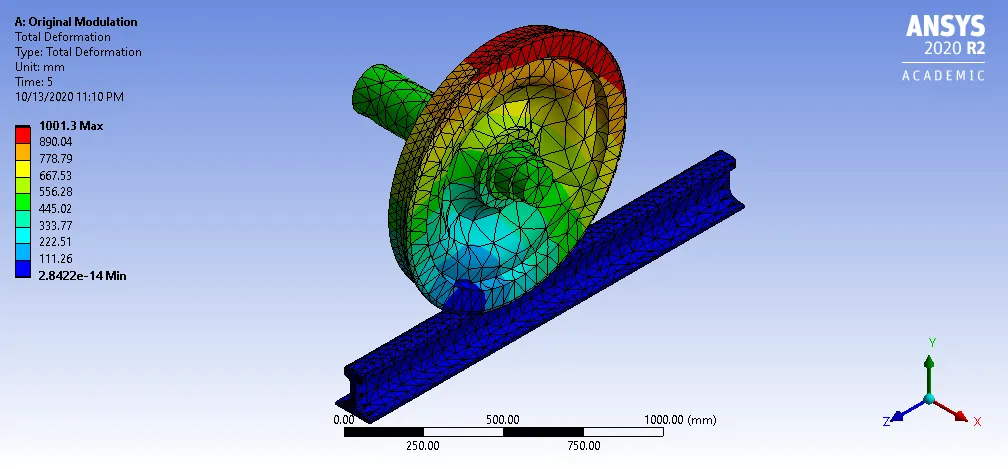
Although different load were given the deformation that occured on both models are similar with negligable difference in its value. The maximum and minimum point of defomation occured on the same pointin both models.They both gave a deformation of 1001.3 mm maximum.
Equivalent Stress:
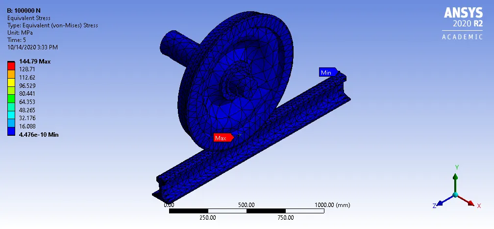
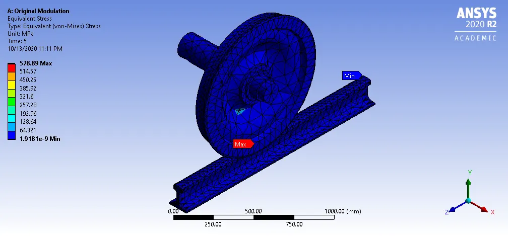
For the load of 100000N the maximum stress produced was 144.79 MPa and for the load for 500000 N the maximum stress produced was 578.89 MPa. This just as expected as higher load means higher stress development. Maximum stress has occured at the point of contact between the wheel and the rail ( which is a line contact).
Life:
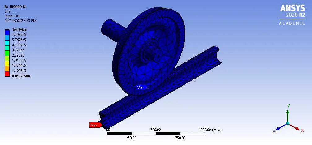
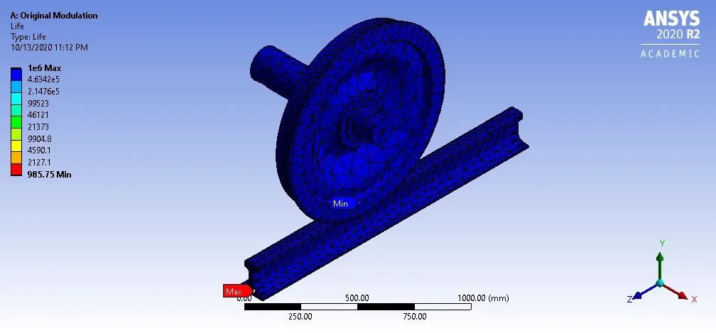
With a load of 100000 N the setup would last for a minimum of 83837 cycles while under the load of 500000N the etup would only last for a minimum of 987.75 cycles. Naturally the higher load would mean more stresse developed and higher wear and tear resulting in earlier failure.
Comparing both the models it is clear that with the higher load the stresses developed is higher and result in a lower reduced life time. However the deformation even with the increased load remains almost similar.
| LOAD | 100000 N | 500000 N |
| MAXIMUM DEFORMATION (mm) | 1001.4 | 1001.3 |
| MAXIMUM STRESS (MPa) | 144.79 | 578.89 |
| MINIMUM LIFE (CYCLES) | 83837 | 985.75 |
CASE 2:
Deformation by Ansys:
Deformation by user defined result:
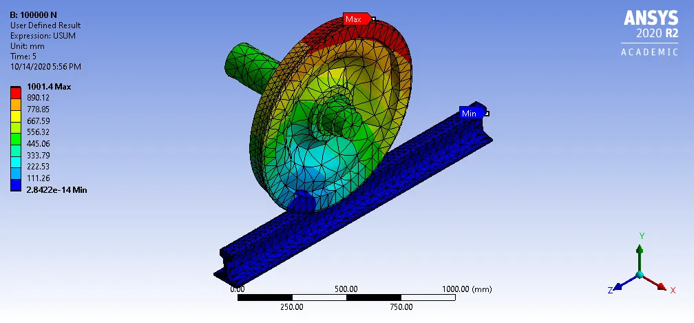
After adding the user defined result from the solutions the output is changed to displacement and an expression of USUM. The expression USUM was found out from the worksheet in solutions and then going into the Available Solution Quantities option. The solution is solved for after giving the expression to which the maximum deformation value I got was 1001.4 mm which is the same as that of the total deformation calculated by the Ansys program.