Week 4- Rolling operation
Analysis
Here we will see Structural Analysis for Rolling Copper Operation.
In which we will put a Copper Rod between two Rolls and extract the sheet form of Copper metal.
Here material will be Copper Alloy NL.
Procedure:
- Import model in Static Structural in Geometry section.
- Change in the geometry as follows:
- Increase length of Copper Workpiece by 60 mm.
- Decrease width of Copper Workpiece by 8 mm.
- We can see that final thickness of Copper rode has been 9 mm.
- Then go to Mechanical model section.
-
- Type: Frictional
- Friction Coefficient: 0.2
- Formulation: Augmented Lagrange
- Normal Stiffness : By factor
- Normal Stiffness Factor: 0.1
- Update Stiffness: Each Iteration
- Interface Treatment: Add Offset, Ramped EffectsRename Roll Wheels and Copper rod as Wheel1, Wheel2 and Box as shown above in geometry
- Connections:
- Delete automatically created contacts and create new contacts as given below:
Contact_1:
Contact Body = Box
Target Body = WHEEL1
Contact_2:
Contact Body = Box
Target Body = WHEEL2
Settings for both Contacts:
Joints:
Joint_1
Connection Type: Body-Ground
Type: Revolute
Body: Wheel1
Joint_2
Connection Type: Body-Ground
Type: Revolute
Body: Wheel2
Boundary Conditions:
- After meshing as described above, create Boundary Conditions as given below:
Analysis Settings:
- No. of Steps: 14
- Auto Time Stepping: Program Controlled
- Solver Type: Program Controlled
- Large Deflection: ON
- Nonlinear Controls:
- Stabilization: Constant
- Method: Energy
- Energy Dissipation Ratio: 0.1
- Other Boundary conditions for joints are as given below:
- Now we want to move the workpiece between two wheels up to 81 mm, so we have to give it a displacement.
- Select the surface of box and give displacement load and give values in tabular column
- Now select the wheels and give revolution joint load and give degree of rotation at each step in tabular graph
- Now run the simulation
Solution:
- After giving proper boundary conditions, create desired solutions for output results.
- Create Solutions for :
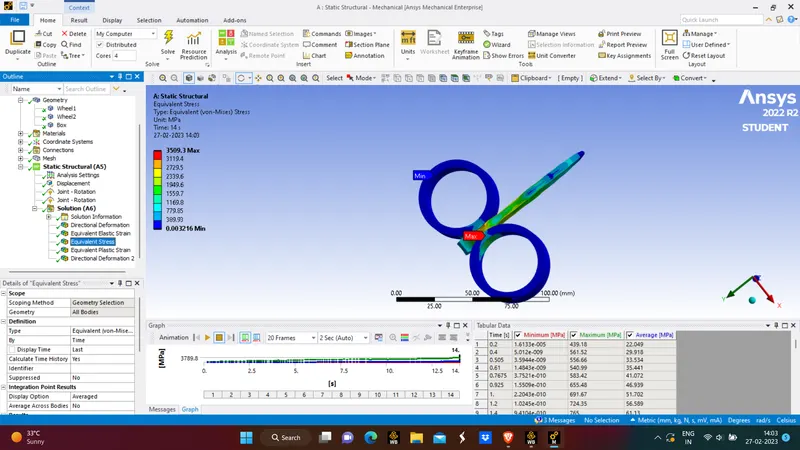
- Equivalent Stress For Whole Setup
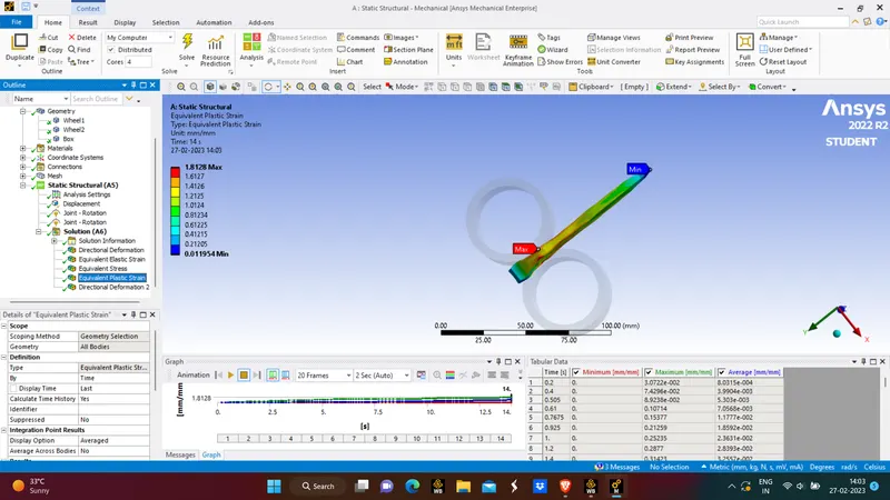
- Equivalent Plastic Strain for the Box
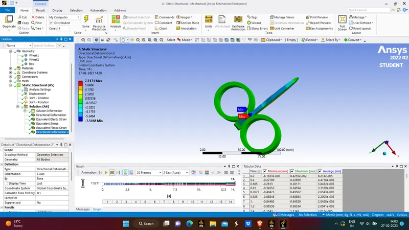
- Directional Deformation in Z-axis for the Box
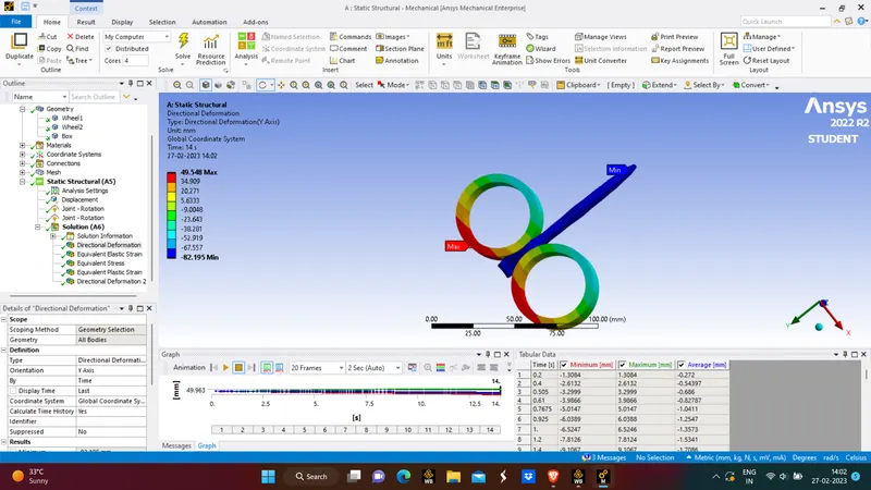
- Directional Deformation in Y-axis for the Box
Result:
Directional Deformation ( Y- Axis)
Directional Deformation (Z-Axis)
Equivalent Stress
Equivalent Plastic Strain
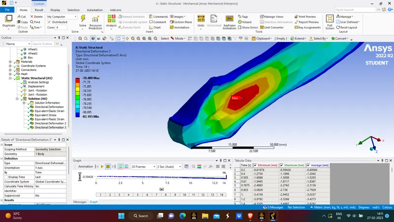
Proof for Displacement of Workpiece up to 90mm:
- Now we want to verify that workpiece has moved or displaced up to 90 mm in Y – Axis direction.
- As we know, we have given Displacement to Workpiece up to 90 mm.
- To verify it, we will see the Direction Deformation of the Workpiece and see that the Tip of the Workpiece has displaced up to 90mm or not.
- Here I gave a max displacement of 81mm so the displacement was 81mm
Conclusion:
This study of the rolling process drew every minute aspect. In terms of manufacturing engineering, every engineer should consider the rolling process as a core metal forming process. This process is mainly used when a cross-sectional area of a material required to be changed by an engineer.