Static structural analysis for rolling operation of copper workpiece
OBJECTIVE:
To stimulate rolling operation by modifying the given model with copper workpiece and evaluate the following results.
- Equivalent stress for the whole setup.
- Equivalent plastic strain for the workpiece.
- Directional deformation in the Z direction for the workpiece.
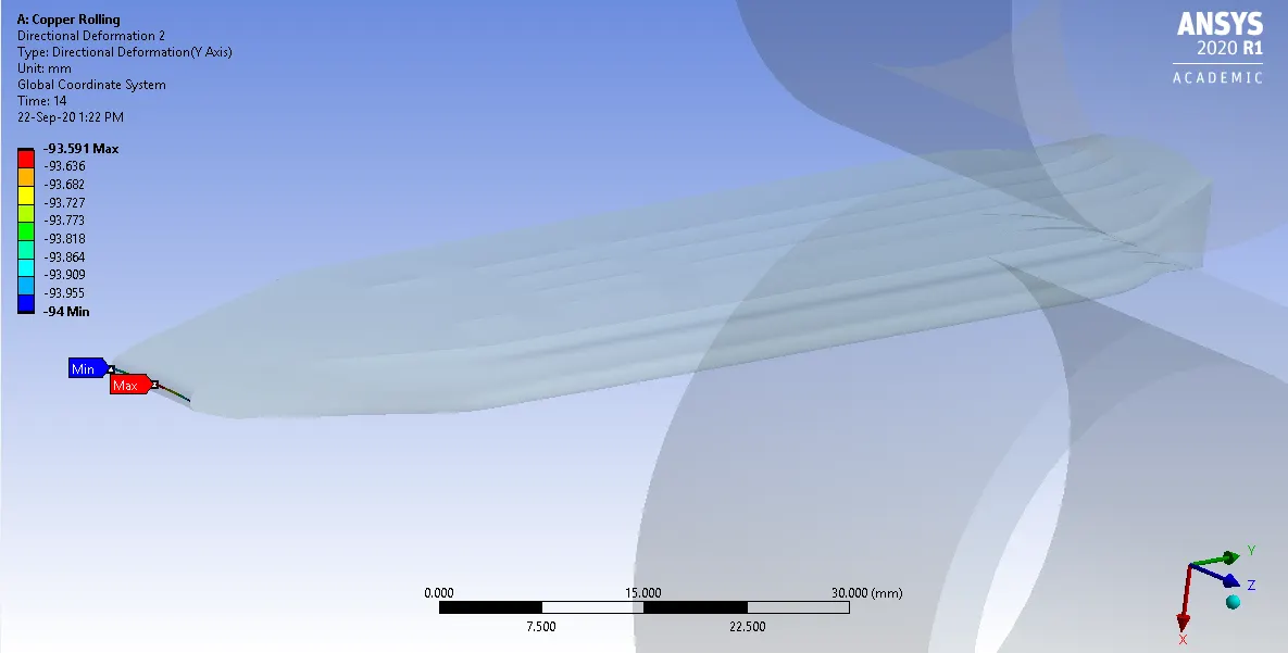
- Prove that the workpiece has displaced by 90mm.
SOLUTION:
STEP 1) Model Design
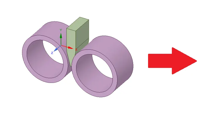
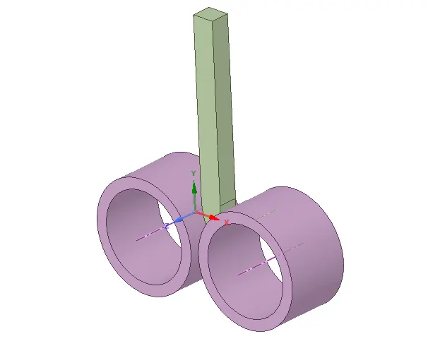
The model consists of two rollers and the workpiece. The following modifications was made on this model:
- Length of the workpiece was increased by 60mm.
- Width of the workpiece was reduced by 8mm from both sides.

STEP 2) Material
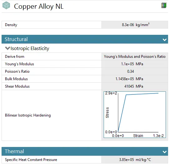
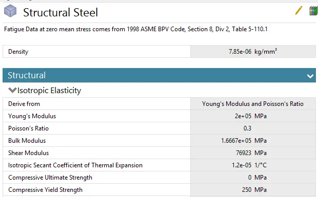
In this stimulation workpiece was assigned Copper Alloy NL and both the rollers were assigned Structural steel. The properties of the materials were given below:
STEP 3) Connections
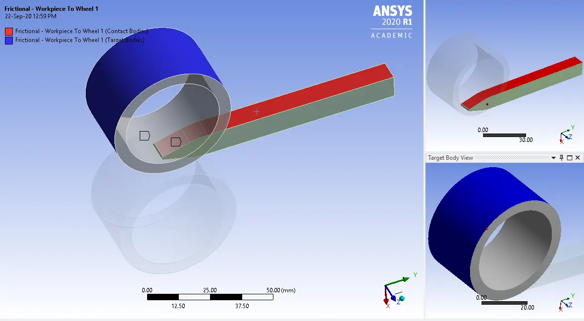
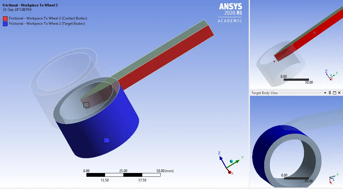
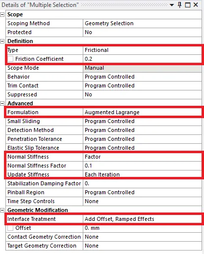
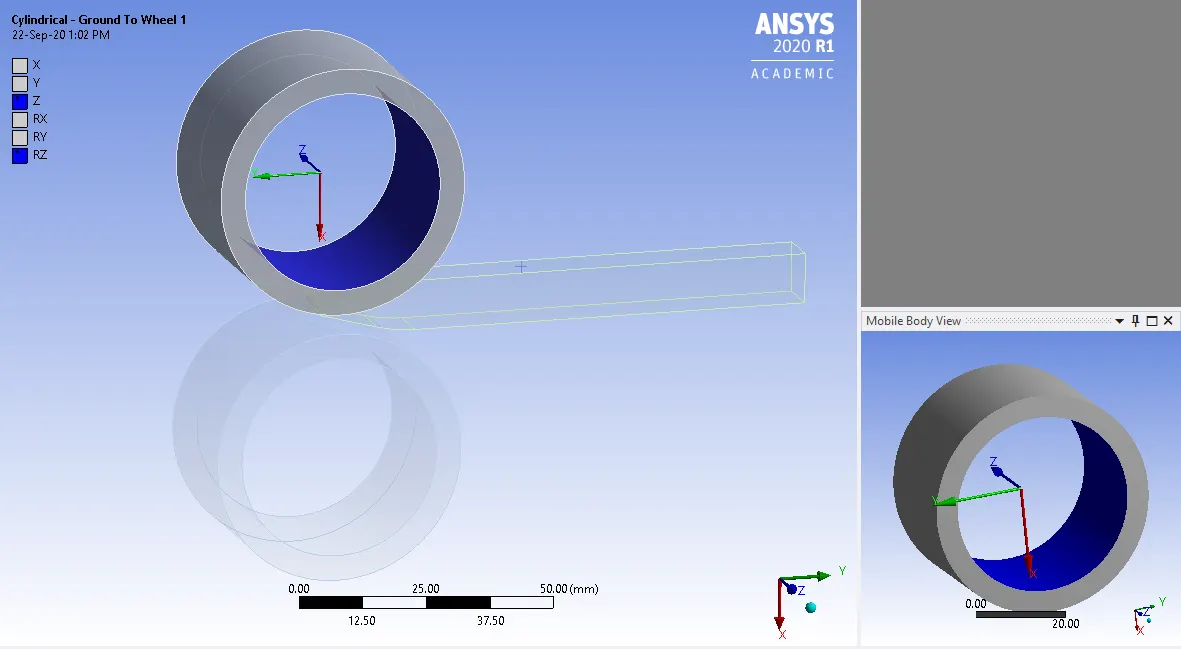
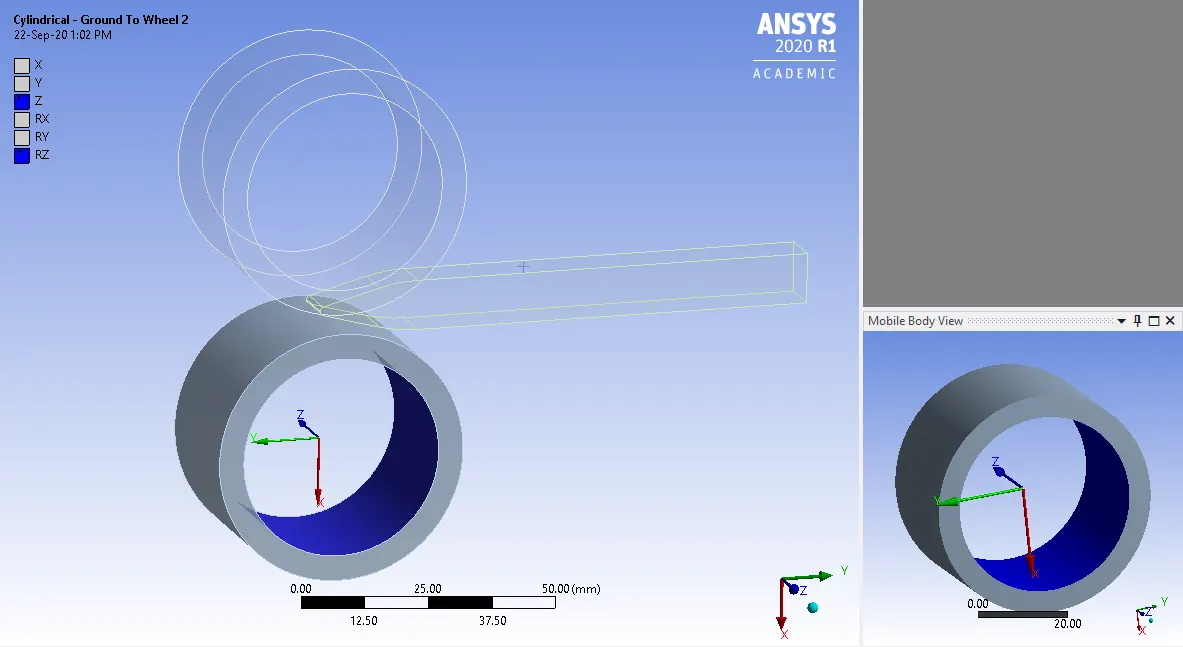
After the assignment of the material we have to define contacts. To carry out this stimulation two contacts were defined, the first was between the upper faces of the workpiece and the upper roller and the second one was between the lower faces of the workpiece and the lower roller. This is illustrated in the following figure. Both the contacts were defined as frictional with coefficient of friction of 0.2, the formulation was defined as augmented langrage, normal stiffness define by factor of 0.1 was given with update stiffness for each iteration and interface treatment was defined as add offset with ramped effects. After define contacts two cylindrical joints were defined for each roller.


STEP 4) Meshing
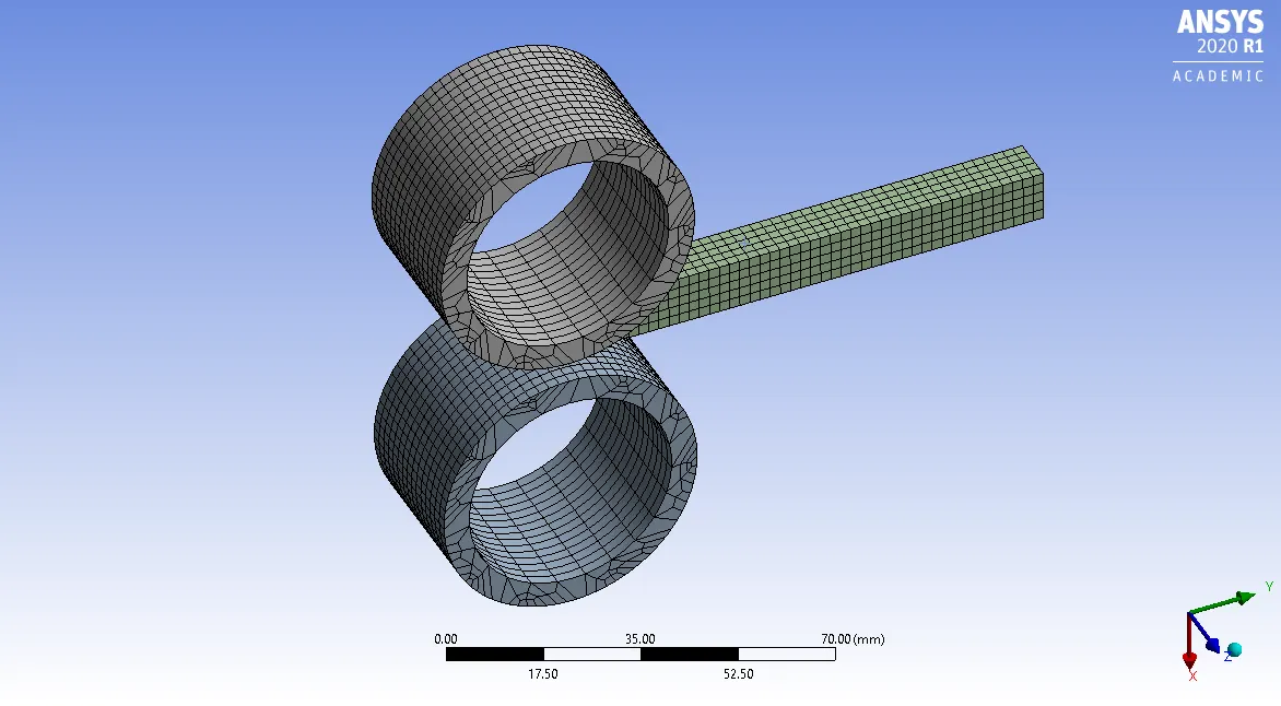
The model was meshed using ANSYS mesher. The workpiece and outer face of both the rollers which is in contact to the workpiece was give mesh size of 2mm and the whole body was given default mesh size.

STEP 5) Analysis settings
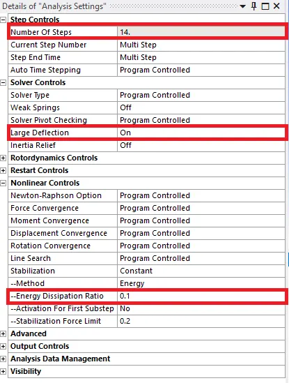
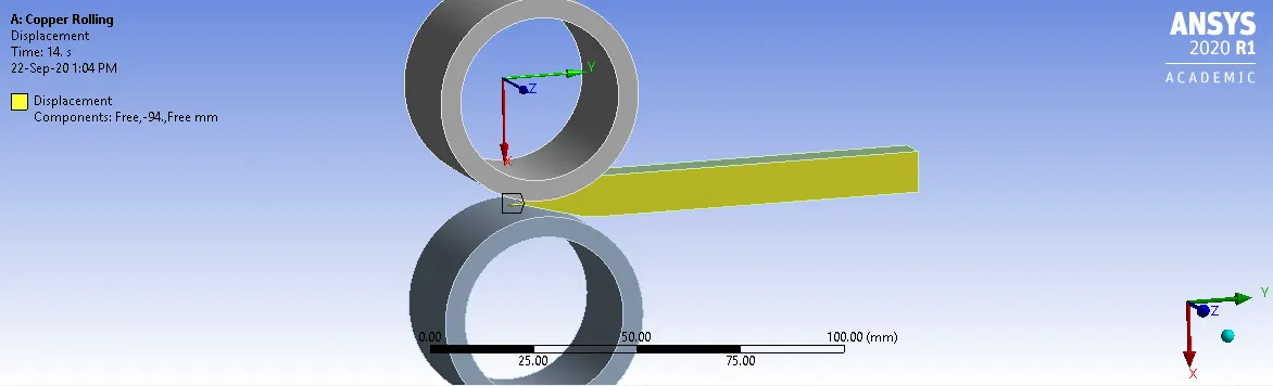
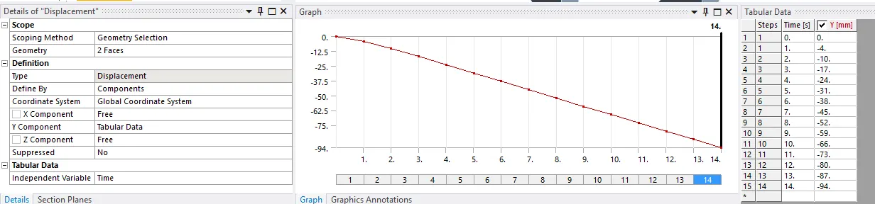
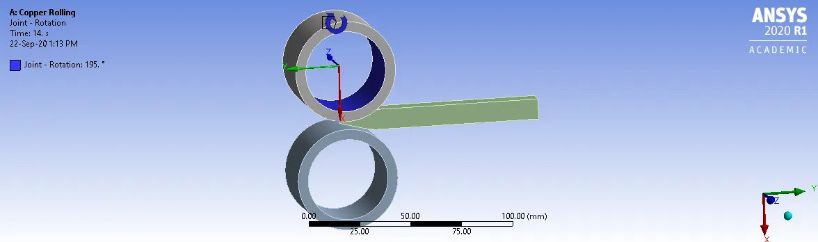
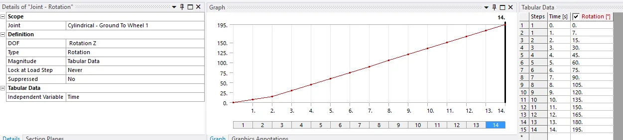
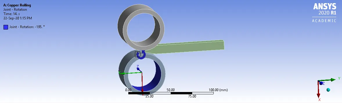
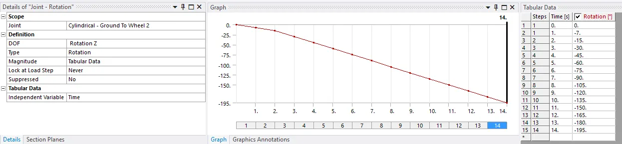
The analysis was carried out over in 14 steps. For each step, large deflection was turned on and energy dissipation ratio of 0.1 was defined. In this stimulation the workpiece has to enter from one end of roller and exit from the other end. So to perform this stimulation we have given a displacement to the two opposite faces of the workpiece, ranging from 0mm to 94mm. Each roller was given rotation along its axis with angle of rotation ranging from 0 to 195 degree.




STEP 6) Result
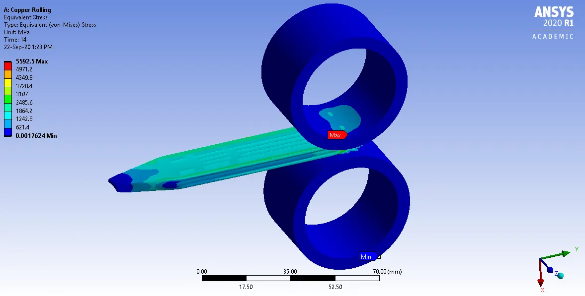
- Equivalent stress for the whole setup

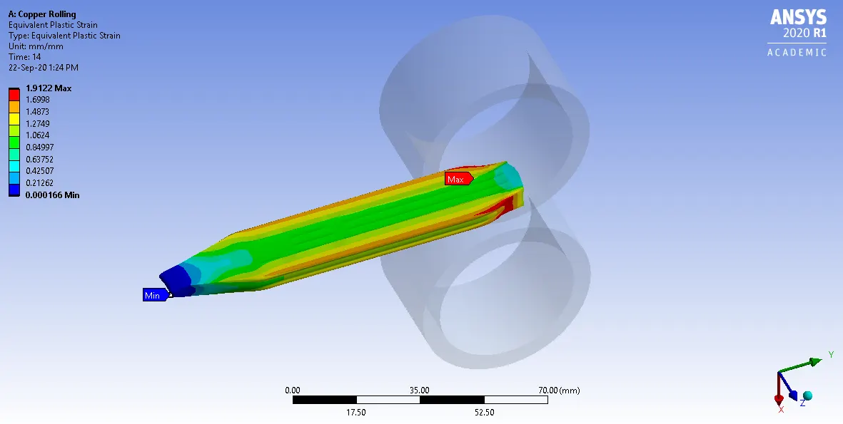
- Equivalent plastic strain for the workpiece

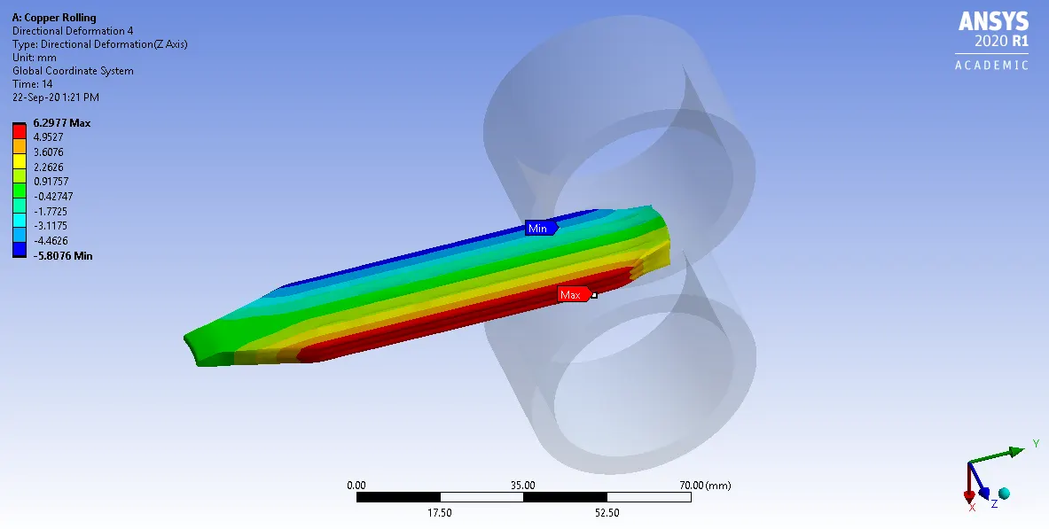
- Directional deformation in the Z axis for the workpiece

- Displacement of the workpiece from its initial position

|
Equivalent stress for the whole setup (MPa) |
Equivalent plastic strain for the workpiece (mm/mm)
|
Directional deformation in the Z axis for the workpiece (mm)
|
Displacement of the workpiece from its initial position (mm)
|
|
|
Max |
5592.5 |
1.9122 |
6.2977 |
-93.591 |
|
Min |
0.0017624 |
0.000166 |
-5.8076 |
-94 |
CONCLUSION:
From the stimulation, we get above results. From above results we can see that the displacement of the workpiece from its initial position is 94mm which prove that the workpiece has indeed displaced by 90mm.
Link for the analysis files is attached.