Week 4- Rolling operation
Rolling Operation
Objective
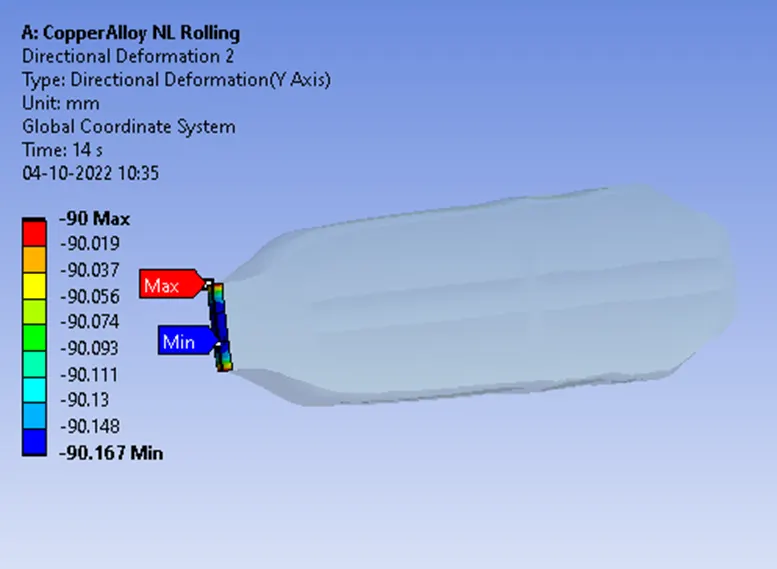
To simulate the rolling operation on a workpiece made of Copper Alloy NL by increasing the length of the workpiece by 60mm and decreasing its size on both sides by 8mm and ensuring that the edge of the workpiece is displaced by 90mm after rolling.
Find out the
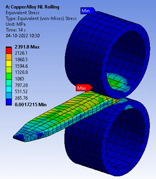
- Equivalent stress for the whole setup
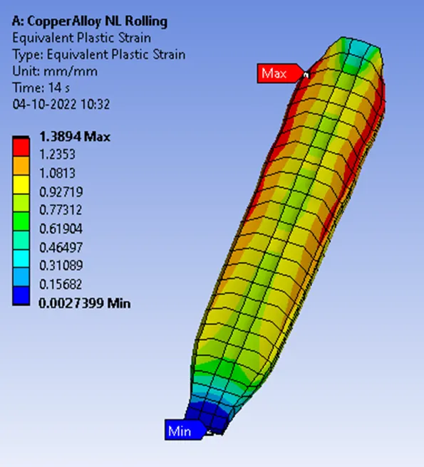
- Equivalent Plastic strain for the workpiece
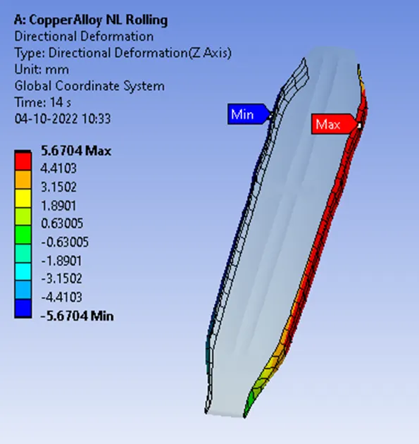
- Directional Deformation in the Z axis for the workpiece
- Prove that the workpiece has displaced by 90mm
Materials Used
Rollers as Structural Steel
Workpiece as Copper Alloy NL
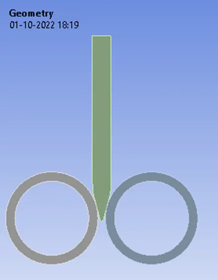
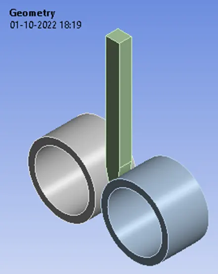
CAD Model of the Rollers & Workpiece is incorporated for Analysis (Front view & Isometric view)
Material Properties have been taken from Engineering Data Sources of Ansys Workbench
|
Material Specifications for |
Density (Kgm^-3) |
Young’s Modulus [MPa] |
Bulk Modulus [MPa] |
Shear Modulus [MPa] |
Yield Strength [MPa] |
Ultimate Strength [MPa] |
|
Copper Alloy NL |
7850 |
2E11 Pa |
1.6667E11 Pa |
7.6923E11 Pa |
2.5E8 Pa |
4.6E8 Pa |
Connections
Contact Settings:
Initiating contact settings is crucial for the designer and end-user since the setting of contact surfaces is at the discretion of the designer as to what to ignore and which to consider. Here the Rollers and Workpiece are in constant contact to undergo dynamic attributes of stresses, strains, and deformations as such the designer have to closely observe and predict the cognitive analytical ability to consider it as crucial for setting the contact region and ignoring other factors for efficient (i.e. Saving Time and Energy) Way of Analysing.
Contacts allowing separation (e.g. frictional contacts) are non-linear contacts. For FE models with non-linear contacts, an iterative process is involved to obtain a solution and therefore non-linear contact analyses are more computationally demanding.
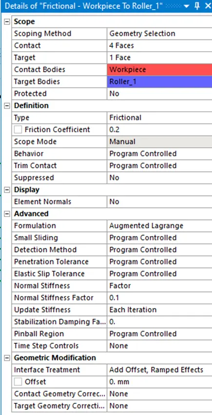
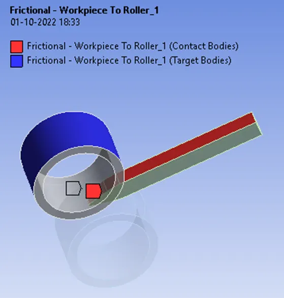
Frictional – Workpiece to Roller_1
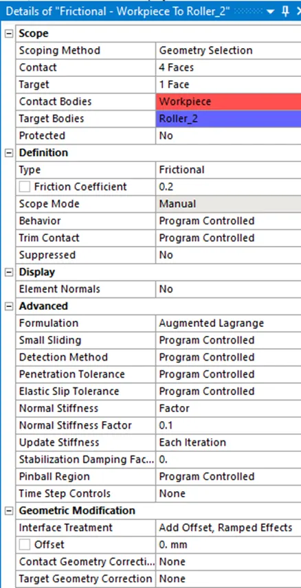
This state is known as “sticking.” The model defines equivalent shear stress (shear stress refers to cases where the deforming force is parallel to a surface) at which sliding on the geometry begins as a fraction of the contact pressure. Once the shear stress is exceeded, the two geometries will slide relative to each other. The coefficient of friction can be any nonnegative value, here we take it as 0.2
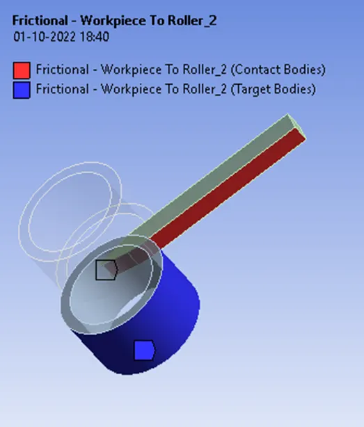
Frictional – Workpiece to Roller_2
Joints
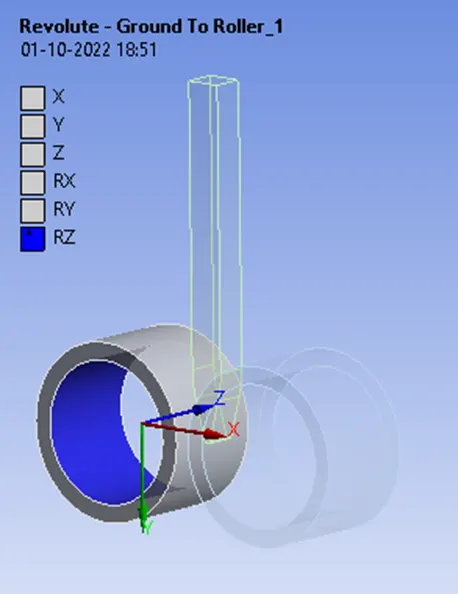
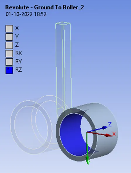
Revolute Joint
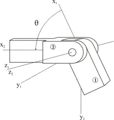
A revolute joint, sometimes called a pin or hinge, is shown in the diagram below with the two bodies and body-fixed reference frames that it connects. A revolute joint allows a single relative rotation of the two frames; this joint type prevents all of the other relative rotations and translations.
In our analysis, the revolute joint is given to the Roller_1 and Roller_2.
Why not a cylindrical joint be used instead?
Because of the rigid body motion dynamics, the rollers are not positioned or displaced when the workpiece enters in between rollers hence facing convergence issues. So, to place perfectly the rollers in their position I picked up the revolute joint as the Body to the ground for a fixed/stable position along RZ only.
Meshing Details
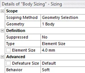
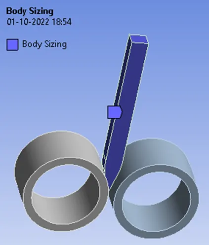
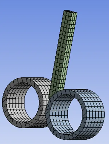
For the meshing part of default solver settings, the ANSYS solver will use the default or recommended mesh value for the model.
Body Sizing
Mesh Metric:
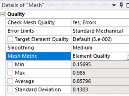
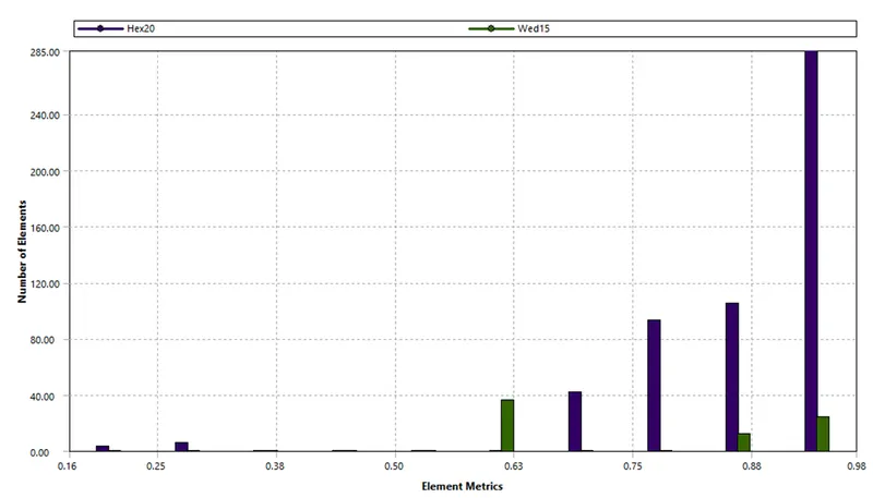
Element Quality
The Element quality option provides a composite quality metric that ranges between 0 and 1 and this metric is based on the ratio of the volume (or area) to the square of the edge length.
So a Value of 1 indicates a perfect cube or square or triangle or hexagon or quad while a Value of 0 indicates that the element has a zero or negative volume.
Boundary Conditions
Analysis settings:
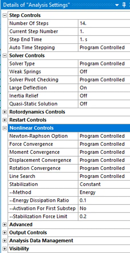
The Time Step controls of Analysis settings are crucial for Convergence of Force and Criterion values /curves as this helps the solver converge without any issues.
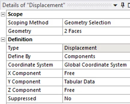
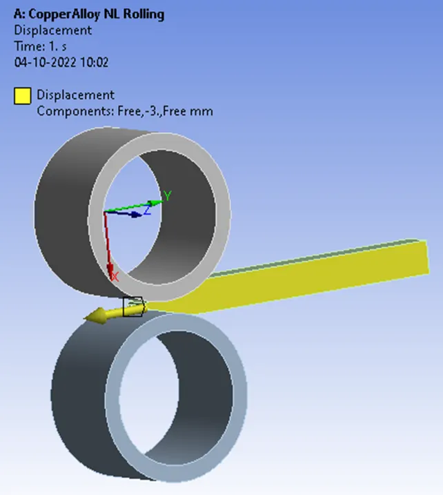
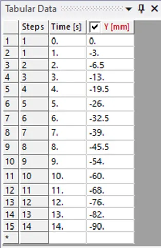
Displacement to Workpiece
Displacement values are given a negative Y direction because of the reference to the Global coordinate system as we consider that the following workpiece will move.
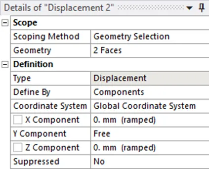
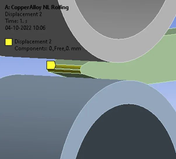
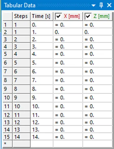
Displacement 2 at Sharp Contour faces of Workpiece
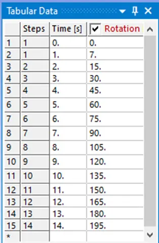
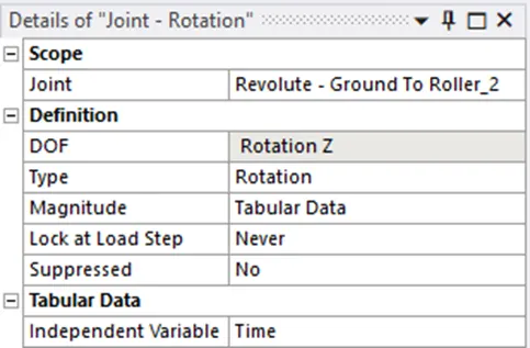
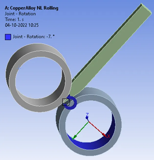
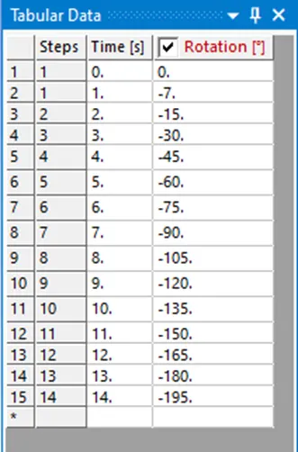
Joint Rotation at Rollers
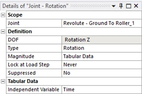
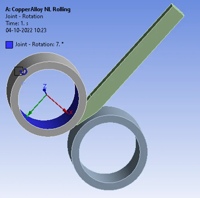
For Roller_1
For Roller_2
Simulation Results
Equivalent Stress
Equivalent Plastic Strain
Directional Deformation in the Z axis for the workpiece
Directional Deformation in the Y axis for the workpiece
We can Observe that the edge of the workpiece is displaced by 90mm.